EP0259052B1 - Einrichtung zum Herstellen einer Zahnprothese und ihr Produkt - Google Patents
Einrichtung zum Herstellen einer Zahnprothese und ihr Produkt Download PDFInfo
- Publication number
- EP0259052B1 EP0259052B1 EP87307287A EP87307287A EP0259052B1 EP 0259052 B1 EP0259052 B1 EP 0259052B1 EP 87307287 A EP87307287 A EP 87307287A EP 87307287 A EP87307287 A EP 87307287A EP 0259052 B1 EP0259052 B1 EP 0259052B1
- Authority
- EP
- European Patent Office
- Prior art keywords
- tooth
- dental prosthesis
- bridge bar
- pontic
- boss
- Prior art date
- Legal status (The legal status is an assumption and is not a legal conclusion. Google has not performed a legal analysis and makes no representation as to the accuracy of the status listed.)
- Expired - Lifetime
Links
- 230000009969 flowable effect Effects 0.000 claims 1
Images


Classifications
-
- A—HUMAN NECESSITIES
- A61—MEDICAL OR VETERINARY SCIENCE; HYGIENE
- A61C—DENTISTRY; APPARATUS OR METHODS FOR ORAL OR DENTAL HYGIENE
- A61C13/00—Dental prostheses; Making same
- A61C13/0003—Making bridge-work, inlays, implants or the like
-
- A—HUMAN NECESSITIES
- A61—MEDICAL OR VETERINARY SCIENCE; HYGIENE
- A61C—DENTISTRY; APPARATUS OR METHODS FOR ORAL OR DENTAL HYGIENE
- A61C13/00—Dental prostheses; Making same
- A61C13/225—Fastening prostheses in the mouth
-
- A—HUMAN NECESSITIES
- A61—MEDICAL OR VETERINARY SCIENCE; HYGIENE
- A61C—DENTISTRY; APPARATUS OR METHODS FOR ORAL OR DENTAL HYGIENE
- A61C13/00—Dental prostheses; Making same
- A61C13/225—Fastening prostheses in the mouth
- A61C13/26—Dentures without palates; Partial dentures, e.g. bridges
-
- A—HUMAN NECESSITIES
- A61—MEDICAL OR VETERINARY SCIENCE; HYGIENE
- A61C—DENTISTRY; APPARATUS OR METHODS FOR ORAL OR DENTAL HYGIENE
- A61C5/00—Filling or capping teeth
- A61C5/30—Securing inlays, onlays or crowns
Definitions
- the present invention relates generally to apparatus for constructing a pontic or pontics to fill an edentulous space adjacent to existing teeth or between two existing teeth and, more particularly, is directed to a method and apparatus for making a pontic or pontics in situ, with minimal adjustments, in one visit.
- a dental bridge to span a gap between two teeth, with one or more pontics, or to replace a missing tooth using a cantilevered pontic applied to one or more teeth.
- the most common method of replacing a missing tooth or teeth is termed fixed coverage.
- the tooth or teeth adjacent to the missing tooth or teeth are ground down, and this usually requires anesthesia.
- an impression is taken of the missing tooth or teeth and the adjacent teeth by use of dental impression trays.
- An interim plastic dental prosthesis or bridge is then usually formed to cover the prepared teeth. This generally completes the end of the first visit with the dentist.
- the impressions are then sent to a laboratory, where a set of model teeth are formed from the impressions made with the impression trays.
- a bridge framework is constructed at the laboratory to fit over the adjacent teeth and to provide a false tooth or teeth (pontic(s)) between the teeth, from the impressions.
- This prosthesis framework, or individual copings is sent back to the dentist, and the patient then, during a second appointment, has the dental framework or copings tested for fit to the ground down teeth. If the framework or copings of the future dental prosthesis does not fit properly, the above procedure may have to be repeated.
- the bridge framework is returned to the laboratory for the application of proper tooth color and returned to the dentist for bite adjustment. Once the bite is ground in, the bridge is returned to the laboratory for final glazing and the like. If the final tooth color is wrong, the bridge may have to be sent back to the laboratory for an additional adjustment.
- the patient may experience four to six visits at the dental office to obtain the fixed bridge, at a considerable inconvenience and cost to the patient.
- European Patent Application EP-A-0242639 discloses a dental prosthesis which comprises a bridge to be supported in the gap between adjacent existing teeth and upon which bridge a prosthesis tooth can be built up and shaped progressively until the desired shape/form is obtained. This is achieved by successive removals and reinsertions of the prosthesis into the gap and by finishing the prosthesis tooth in situ. This application can only be considered under Article 54 (3) EPC for the purposes of novelty.
- a dental prosthesis for forming at least one pontic adjacent at least one tooth and its adjacent gum surface of the kind comprising: a support having means for connecting it to at least one tooth; a mould adapted to be carried by the support, is characterised in that: there is provided an adjustment assembly for relating the support and the undersurface of the pontic to be formed before it is fixedly connected in assembled position to said at least one tooth, said adjustment assembly comprising at least one centrally disposed member on the support for location adjacent said at least one tooth above the gum surface in the region of the edentulous space and an adjustment member movably connected to the centrally disposed means for engagement with and adjustment in relation to said gum surface to adjust the occluso-gingival height of the support with respect to the gum surface.
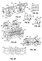
- a bridge bar assembly 30 generally includes a cylindrical boss 32 with a centrally positioned screw-threaded aperture 34 extending entirely therethrough.
- boss 32 is shown as being of a cylindrical configuration, it will be appreciated that the present invention is not so limited and that boss 32 may include other configurations, such as a square box-like configuration or the like.
- a bridge bar 36 extends diametrically from opposite sides of boss 32. Specifically, bridge bar 36 is formed of a first bridge bar section 38 extending radially outward from the outer surface of boss 32 and a second bridge bar section 40 also extending radially outward from the outer surface of boss 32 and being diametrically opposite first brdige bar section 38.
- each bridge bar section 38 and 40 has an upwardly tapered or substantially triangular configuration in order to increase the volume of composite or other plastic or toothlike material to be placed next to bridge bar 36, while providing a sufficiently wide lower surface 42 for supporting bridge bar sections 38 and 40 in a stable manner within grooves formed in adjacent teeth, as will be described in greater detail hereinafter.
- first and second bridge bar sections 38 and 40 are formed integrally with boss 32, although such sections may be separately attached to boss 32.
- Bridge bar assembly 30 further includes a pontic base 44 having a generally convex shaped lower surface 46.
- a screw-threaded shaft 48 extends from the upper surface 50 of pontic base 44 and is screw-threadedly received within aperture 34 of boss 32 to permit vertical adjustment of pontic base 44 with respect to boss 32.
- Bridge bar assembly 30 is used in a method for forming a pontic (pontics) or false tooth (teeth) between a first tooth and a second tooth posteriorly positioned with respect to the first tooth, said pontic or pontics resting lightly on the gum surface therebetween.
- FIGURES 5-10 a first method of forming a pontic according to the present invention will be described.
- a pontic (or pontics) 52 is formed in situ in an edentulous space defined between a first anterior tooth 54 (or two anterior teeth) and a second tooth 56 posteriorly positioned with respect to first tooth 54 and resting lightly on the gum surface 58 therebetween.
- first tooth 54 or two adjacent teeth
- second tooth 56 posteriorly positioned with respect to first tooth 54 and resting lightly on the gum surface 58 therebetween.
- first tooth 54 or two adjacent teeth
- mesial and occlusal surfaces of second tooth 56 are likewise drilled to form a second groove 62.
- Each groove is drilled to an adequate depth. Drilling of the more posterior of the teeth extends through the mesial marginal ridge, and then up to the distal marginal ridge.
- Drilling of the anterior tooth extends through the distal marginal ridge and up to the mesial marginal ridge.
- a number 35 inverted cone bur or similar bur can be used for drilling the grooves.
- Each groove 60 and 62 faces the other for receiving the free ends of first and second bridge bar sections 38 and 40, respectively.
- each bridge bar section 38 and 40 rests on the occlusal floor of the cut-away portion of each tooth which defines grooves 60 and 62.
- Pontic base 44 is screw-threaded up into the boss 32 so that the base position rests lightly on the gum surface in the edentulous space between first and second teeth 54 and 56, while the lower surface 42 of the bridge bar rests on the occlusal floor of the grooves in the teeth.
- pontic base 44 is screw-threaded down into light contact with the gum surface, as shown in FIGURE 8.
- pontic base 44 is preferably fabricated from a highly polished metal so as to substantially prevent plaque retention on lower surface 46 thereof.
- the means of raising and lowering said pontic base 15 is not to be limited to a screw mechanism but could also be a vertically sliding mechanism, such as a hex, square, rectangular or other odd-shaped shaft 48a which is non-rotatably inserted into a corresponding bore 34a of boss 32 and into pontic base 44a and slid up and down into boss 32, by a friction fit, as shown in FIGURE 4A.
- the shaft 48 or 48a could be made to extend above boss 32 to be engaged for turning or sliding movement to move pontic base 44a downward to rest lightly on the gum, when bridge bar 36 is positioned to rest on the occlusal floors of grooves in the adjacent teeth. If a friction fit method is used for vertical adjustment, the shaft is slid gingivally through the bridge bar bore until pontic lower surface 44 rests lightly on the tissue.
- a mechanically held arrangement can be provided.
- a wire or plastic mesh core 53b is attached to pontic base 44b, specifically to nub 44x, and connected via a plastic locking material 51b.
- the lower surface of pontic base 44 is placed properly positioned on the gingival surface.
- Bridge bar 40 is positioned in the grooves in the teeth.
- a flat rectangular metal or plastic locking tab 48b having holes 49b can now be inserted gingivalward through bore 34b of boss 32. Locking tab 48b is slipped downward until its inferior border rests on the superior surface of mesh core 53b.
- tab 48b is joined to mesh core 53b via the plastic locking material 51b.
- bore 34b is filled with the plastic locking material 51b to mechanically bond tab 48b within bore 34b, and the portion of tab 48b extending above boss 32 is cut. The above steps apply to forming a lower pontic.
- the steps would be reversed for forming an upper pontic in that the pontic base would be attached to mesh core 53b, the mesh core 53b to vertical locking tab 48b, and tab 48b placed loosely through bore 34b.
- the bridge bar 36 is placed within the tooth grooves and held by soft wax. Holding the pontic base against the gingival edentulous surface, the locking tab 48b is now locked with plastic locking material 51b to mechanically bond tab 48b is now locked with plastic locking material 51b to mechanically bond tab 48b within bore 34b.
- FIGURES 4B and 4C can be made.
- tab 48b can be eliminated and replaced entirely by mesh core 53b which may be moved vertically through bore 34b and secured therein by any suitable means, and then trimmed at its upper end.
- mesh core 53b can be eliminated, with tab 48b connected directly to pontic base 44b.
- the important aspect of the invention is that pontic base 44 is vertically adjustable via the shaft so that it rests lightly on the gum before finally securing the shaft to the bridge bar.
- different pontic bases 44 having slightly different convex shaped lower surfaces 46 may be removed from and separately attached to screw-threaded shaft 48, hex-shaft 48a, tab 48b or mesh core 53b, to permit better selection of pontic shapes which relate both to the gum ridge and the adjacent teeth 54 and 56.
- the lower surface of the pontic base 44 ⁇ can be flat and/or have a ridge lap 46 ⁇ , as shown in FIGURES 4D and 4E.
- Ridge lap 46 ⁇ of pontic base 44 ⁇ is provided on the buccal side to more accurately permit the composite buildup to simulate a real tooth.
- Pontic base 44 ⁇ may be made in an assortment of shapes to account for different ridge shapes. With this embodiment, it is preferably to use a specially created diamond high (or low) speed bur to create a pre-shaped superficial abrasion or indentation in the ridge, which will heal rapidly and when healed, conform to the highly polished undersurface of the pontic base.
- the shape of the portion of the diamond bur which creates the tissue indentation as seen in profile is a long ellipse, and the three-dimensional shape seen in profile is an attenuated oval.
- pontic base 44 ⁇ is formed with a bore 45 ⁇ extending therethrough, whereby a hex shaft 48 ⁇ can be removably secured thereto.
- first and second bridge bar sections 38 and 40 are used at the free ends of first and second bridge bar sections 38 and 40 to secure them in place within grooves 60 and 62, respectively.
- a small portion of wax, acrylic or composite can be used around shaft 48 to prevent rotation of the latter within boss 32 after pontic base 44 has been adjusted.
- each mold half includes an aperture 68 and 70, respectively, the occlusal most portion which conforms substantially to the occlusal-most cross-sectional configuration of first and second bridge bar sections 38 and 40, and is vertically large enough such that mold halves 64 and 66 may be placed in a gingival direction with one mold half on one side of the boss and the other on the opposite side of the boss, having slid the mold halves onto the bridge bar sections 38 and 40 and positioned in proper relationship to the occlusal level of adjacent teeth, and to the pontic base 44, as shown in FIGURE 6.
- the lower surfaces of mold halves 64 and 66 are cut away in an arcuate configuration at 72 and 74, respectively, to permit the convex shaped lower surface 46 of pontic base 44 to fit therethrough, as shown in FIGURES 6 and 8.
- the side edges 76 of mold halves 64 and 66 are slightly cut away so that, when mold halves 64 and 66 are supported on first and second bridge bar sections 38 and 40, respectively, adjacent side edges 76 are spaced from each other, as shown in FIGURE 6.
- the mold halves may take different shapes, but with each mold half having an aperture for receiving the beam and against which the composite or plastic may be packed.
- bridge bar assembly 30 is positioned in the edentulous space between first tooth 54 and second tooth 56 such that the ends of first and second bridge bar sections are positioned and supported within first and second grooves 60 and 62, respectively. Then, bridge bar assembly 30 is adjusted with respect to teeth 54 and 56, as described above, so that mold halves 64 and 66, filled with a plastic material (like a composite resin), are positioned on first and second bridge bar sections 38 and 40, respectively.
- a plastic material like a composite resin
- apertures 68 and 70 can be elongated to the bottoms of mold halves 64 and 66, that is, to arcuate cut-away sections 72 and 74, to form elongated slots 68a and 70a, respectively. Then, each mold half 64 and 66 can be packed with the pontic forming material and vertically push down into position on bridge bar 36, rendering the procedure easier and simpler.
- the pontic forming material is then made to set either chemically or catalytically. Thereupon, the formed pontic 52 and bridge bar assembly 30 are removed from teeth 54 and 56, and mold halves 64 and 66 are removed from first and second bridge bar sections 38 and 40, respectively, so that the product shown in FIGURE 9 is produced. At this time, any final shaping of pontic 52 is performed, with any flash being polished from the undersurface and sides of pontic 52. It is an important aspect of the present invention to provide removal of the assembly shown in FIGURE 9 before cementing it in permanently, so that the underside of pontic base 44 can be polished. The surfaces are polished with discs, burs, pastes or the like. Further, any final color modifications on the buccal side of pontic 52 is made with composites, plastics and available staining techniques. The finished and polished assembly is now ready for final insertion into the mouth of the patient.
- first and second bridge bar sections 38 and 40 which rest in the occlusal surfaces of grooves 58 and 60, and such occlusal surfaces are likewise cleaned of wax.
- the finished and polished pontic 52 is now ready for final insertion.
- a small amount of composite paste is placed on the occlusal surfaces within grooves 60 and 62 to fix the free ends of first and second bridge bar sections 38 and 40 therein. This is then chemically or catalytically cured. Additional composite is then placed over the exposed bridge bar sections 38 and 40 so as to fill grooves 60 and 62.
- a thin flexible, non-adhesive "Saran” wrap-like material is then placed over the opposing tooth.
- the patient then bites down to obtain an exact imprint of the occlusal surface of the opposing tooth.
- the "Saran” wrap-like material is removed and the composite is made to set chemically or catalytically ("light cure”).
- the bite is adjusted by removing any excess from the occlusal surface of pontic 52 with finishing burrs, and then polishing the same, to produce the result shown in FIGURE 10.
- the entire procedure of forming a dental bridge can be performed in a single visit, without the requirement of any laboratory work, with reduced time and with a greatly reduced cost savings for the patient up to 60% from conventional methods.
- accurate adjustment of the undersurface of pontic 52 is achieved with pontic base 44.
- FIGURES 11-18 there is shown a second embodiment of the present invention, in which elements similar to those in the first embodiment of FIGURES 5-10 are represented by the same numerals, and a detailed description thereof will be omitted herein for the sake of brevity.
- the same bridge bar assembly 30 is used, but in conjunction with different mold halves.
- a perforated flexible backing plate 78 which is at least 1.25 - 1.5 inches long is provided for forming each mold half.
- Each perforated back plate 78 has a slightly arcuate configuration, thereby conforming to the arcuate arrangement of first tooth 54, second tooth 56 and the pontic to be formed therebetween.
- Each perforated backing plate 78 also includes a plurality of apertures 80 therein.
- a mold forming material 82 such as silicone, rubber, polysiloxane or any other impression material, is applied to the convex inner surface of a backing plate 78 (the lingual mold) with a thickness of, for example, 3 mm, and for forming the other mold half on the buccal side of teeth 54 and 56, the same mold forming material 82 is positioned on the concave surface of a second backing plate 78.
- the buccal side backing plate will be referred to by numeral 78a and the lingual side backing plate by numeral 78b.
- two embrasure forming wedge 45 (FIGURE 15A), shaped specifically to provide adequate cleansing space upon their removal, are placed on the mesial surface of the distal or posterior tooth 56, at the gingiva, and on the distal surface of the front or mesial tooth 54 at the gingiva. These wedges are tack bonded onto the teeth 54 and 56 after being shaped to curve slightly onto the buccal and lingual surfaces thereof.
- Tooth forming core 83 is then positioned within the edentulous space between first and second teeth 54 and 56 and held by wax to teeth 54 and 56.
- Tooth forming core 83 may be a preformed core chosen from a number of different configurations.
- tooth forming core 83 can be formed from a ball of wax configured in the approximate shape of the pontic 52 to be formed.
- backing plates 78a and 78b with the mold forming material 82 thereon are positioned against the buccal and lingual sides of first and second teeth 54 and 56 and tooth forming core 83, as shown in FIGURE 13.
- U-shaped metal clamps 84 extend over the occlusal surfaces of teeth 54 and 56 and engage the free surfaces of backing plates 78a and 78b to secure the latter against the buccal and lingual sides of first and second teeth 54 and 56 and tooth forming core 83.
- the ends of clamps 84 are preferably bent inwardly to better grip backing plates 78a and 78b.
- the mold forming material may also be placed on the sides thereof facing away from the teeth before placing the clamp.
- a lanyard 86 is secured within an aperture 88 of each clamp 84 to readily permit removal of clamps 84 from the mouth of the patient and to prevent swallowing the clamp.
- the mold forming material on backing plates 78a and 78b is then permitted to set for approximately three minutes or slightly longer, whereupon clamps 84 are removed to permit removal of the formed buccal mold half 90 and lingual mold half 92.
- the latter can be painted with an oil.
- Bridge bar assembly 30 is then positioned in the edentulous space such that first and second bridge bar sections 38 and 40 are positioned and supported within grooves 60 and 62, respectively.
- pontic base 44 is screwed occlusally, or slid occlusally up into the boss, and adjusted until the undersurface of pontic base 44 rests lightly on the gum surface in the edentulous space between teeth 54 and 56.
- the pontic base can be adjusted by sliding or turning element 48 where it extends occlusally through the boss, and adjusting it gingivally.
- a small amount of wax can be used to secure first and second bridge bar sections 38 and 40 within grooves 60 and 62, respectively.
- embrasure forming wedges 45 are inserted at the gum level between pontic base 44 and adjacent teeth 54 and 56.
- each embrasure forming wedge 45 has a triangular cross-sectional configuration and is formed with a concave upper surface 45a.
- Such embrasure forming wedges aid in more accurately defining the pontic to be formed.
- Buccal and lingual mold halves 90 and 92 are then positioned about first and second teeth 54 and 56 and about the edentulous space therebetween. Then, U-shaped clamps 84 again are inserted about mold halves 90, 92 to clamp the same about first tooth 54 and second tooth 56, as shown in FIGURE 16.
- the edentulous space between first and second teeth 54 and 56 and between mold halves 90 and 92 is then filled gradually with a pontic forming material, such as a plastic, or resin composite paste, made to set until the material extends above the occlusal surfaces of teeth 54 and 56, to form a pontic 52 surrounding boss 32 on bridge bar assembly 30.
- a pontic forming material such as a plastic, or resin composite paste
- U-shaped clamps 84 and mold halves 90 and 92 are removed.
- the bridge bar with pontic base are now removed and the flash (excess plastic or composite) removed and the sides and undersurface of the pontic base polished as previously described.
- any final color modifications on the buccal side can be made with the composite paste, or by available staining techniques.
- pontic 52 is formed surrounding bridge bar assembly 30, as shown in FIGURE 9, and is assembled with respect to first and second teeth 54 and 56 in an identical manner to that previously described with respect to the first embodiment of FIGURES 5-10, with the additional step of removing the aforementioned embrasure forming wedges.
- the end result is shown in FIGURE 18.
- Another way of forming the pontic is only using the lingual backing plate, finger held, and embrasure forming wedges, and building up the composite toward the buccal side by hand, shaping and curing as one builds up. Final color modifications and staining are handled the same way.
- a single pontic 52 is formed for filling a one tooth edentulous space.
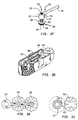
- FIGURES 19-25 there is shown a third embodiment of the present invention, in which elements similar to those described above with respect to the first and second embodiments will be identified by the same reference numerals, and a detailed description thereof will be omitted herein for the sake of brevity.
- a modified bridge bar assembly 94 generally includes at least one boss 96 of a generally rectangular configuration and having a slot 98 extending entirely therethrough, in the lengthwise direction thereof, for receiving a single bridge bar 100.
- bridge bar 100 has a substantially triangular cross-sectional configuration as with bridge bar 36, and each slot 98 has a similar configuration.
- each boss 96 is supported and can be slid along bridge bar 100.
- one side wall of each boss 96 includes a screw-threaded aperture 102 extending entirely therethrough, and a set screw 104 is screw-threadedly received within each aperture 102.
- set screw 104 can be screwed into engagement with bridge bar 100 to retain the respective boss 96 on bridge bar 100 in a fixed position.
- the lower surface 106 of each boss 96 includes a screw-threaded aperture 108, and a pontic base 44 which is identical to pontic base 44 of the first two embodiments has a screw-threaded shaft 48 extending from the upper surface 50 thereof screw-threadedly received within the aperture at the lower surface of each respective boss 96.
- bridge bar assembly 94 is more versatile than bridge bar assembly 30, since it readily permits more than one boss 96 thereon and provides adjustment of each boss in the lengthwise direction with respect to bridge bar 100.
- one boss may be fixed and the other one movable on bridge bar 100.
- the external shape of the boss may vary.
- a buccal mold half 112 and a lingual mold half 114 are formed in the same manner as described in the second emboidment with respect to mold halves 90 and 92, the difference being that, in the third embodiment, a two tooth edentulous space area is covered by mold halves 112 and 114.
- bridge bar assembly 94 is positioned within the edentulous space between first tooth 54 and second tooth 56. Where there are two abutment teeth adjacent on either side of the edentulous space, it is preferable to have bridge bar 100 longer, passing into both teeth, be they posterior and/or anterior to the space.
- each boss 96 is slid along bridge bar 100 to the desired position and fixed thereat by means of set screws 102.
- Each pontic base 44 is then screwed up into the undersurface of boss 96 and the assembly tested for proximity of fit of the base 44 to rest light on the gum surface. If the bar part of the assembly does not fit on the occlusal floor of the grooves when the pontic bases touch the gum, then the screw and base are removed and shortened until the screw portion is short enough to permit the transverse beam 100 to rest on the floor of the grooves while the pontic bases lightly touch the gum. Then, mold halves 112 and 114 are secured to the buccal and lingual sides of first and second teeth 54 and 56 by U-shaped clamps 84.
- the edentulous space between first tooth 54 and second tooth 56 and between mold backing halves 112 and 114 and the mold itself (which was formed previously by wax shaping the two pontics and then using an elastic material like a polysiloxane to pick up the wax shape of the future pontics) is now filled with a pontic forming material.
- the pontic forming material is made to chemically or catalytically set, whereupon clamps 84 and mold halves 112 and 114 are removed.
- the remainder of the operation is identical to that previously described in regard to the embodiment of FIGURES 5-10 and need not be described in detail.
- the end result is shown in FIGURE 25. It is noted that the method of FIGURES 1-10 can also be used with this embodiment.
- boss 32 can be eliminated, with shaft 48 being screw-threaded directly into bridge bar 36, in the first and second embodiments.
- the present invention can be modified to operate in a cantilevered fashion from only one tooth.
- the present invention can be used to form a pontic with two adjacent teeth, that is, secured to the teeth in a cantilevered fashion, where the edentulous space is posterior to the remaining teeth, and a single pontic tooth is needed to occlude with an opposing tooth.
- a bridge bar assembly 130 is used which is substantially identical to bridge bar assembly 30 of the first two embodiments, in which elements similar to those of bridge bar assembly 30 are represented by the same numerals augmented by 100, and a detailed description thereof will be omitted herein for the sake of brevity.
- bridge bar assembly 130 is identical to bridge bar assembly 30, with the exception that bridge bar 136 is formed with only a first bridge bar section 138 extending from one side of boss 132.
- bridge bar section 138 of bridge bar assembly 130 corresponds to bridge bar 38 of bridge bar assembly 30, and there is no bridge bar section corresponding to bridge bar section 40 of bridge bar assembly 30.
- bridge bar section 138 extending from one side of boss 132 is preferably elongated so as to span two adjacent teeth 154 and 156.
- a bracing section 139 is integrally formed with boss 132 toward the gingival side of bridge bar section 138 for providing additional support for the same.
- bracing section 139 is provided so that sufficient pontic forming material is provided about the pontic base and boss.
- bracing section 139 has a width equal to the width of bride bar section 138 and the lower surface 141 thereof is slightly inclined occlusally at a small angle so that there is sufficient space for interdental cleansing if boss 132 is positioned close to pontic base 144. It is also preferable to somewhat flatten the distal side of tooth 154, as shown at 154a in FIGURES 31 and 32, to provide greater strength to the assembly.
- a perforated backing plate 178 is formed of a metal material.
- Backing plate 178 is formed in a substantially U-shaped configuration and has inturned ends 179 at the free ends thereof which face each other.
- a mold forming material 182 is applied to the inner surfaces of backing plate 178.
- Mold forming material 82 may be a silicone, rubber, polysiloxane or any other impression material and is preferably applied with a thickness of, for example, 3 mm.
- Tooth forming core 183 is positioned adjacent the tooth 154 and held with wax to tooth 154.
- Tooth forming core 183 may be a preformed core chosen from a number of different configurations.
- tooth forming core 183 can be formed from a ball of wax configured in the approximate shape of the pontic 152 to be formed.
- a second alternative is to drill the grooves in the two anterior teeth, place the bridge bar assembly, securing it with wax occlusally to the two teeth, and then shaping the pontic in wax about the shaft and pontic base. The impressions with mold halves are now taken.
- backing plate 178 with the mold forming material 182 thereon is positioned against the buccal and lingual sides of tooth forming core 183, and preferably the next two adjacent teeth 154 and 156, both of teeth 154 and 156 being positioned on the same side of tooth forming core 183, as shown in FIGURE 33.
- a U-shaped metal clamp 184 extends over the occlusal surfaces of teeth 154 and 156 and engages the free surfaces of backing plate 178 to secure the latter against the buccal and lingual sides of teeth 154 and 156 and tooth forming core 183.
- the mold forming material also be on the sides of backing plate 178 facing away from the teeth in order to provide better grasping thereof by clamp 184.
- a lanyard 186 is secured to clamp 184 in the same manner as in the embodiment of FIGURE 17.
- mold forming material 182 on backing plate 178 is then permitted to set for approximately three minutes or slightly longer, whereupon claim 184 is removed to permit removal of the formed mold 190, as shown in FIGURE 34.
- mold 190 has a U-shaped configuration and is formed of the mold forming material 182 and backing plate 178.
- the inner surfaces of mold 190 are defined to conform to first and second teeth 154 and 156 and the tooth forming core 183.
- tooth forming core 183 is removed, and a groove 160 is formed in teeth 154 and 156 in the identical manner as described in the aforementioned embodiments.
- Bridge bar assembly 130 is then positioned adjacent to teeth 154 and 156 such that bridge bar section 138 is positioned and supported within groove 160.
- the groove would be in two adjacent teeth and the bridge bar extend into both grooves. Then, pontic base 144 is screwed or slid occlusally into the boss and tested for proximity to the gum surface adjacent tooth 154. As previously discussed, the shaft can also be used in a downward adjusting manner if sufficient length extends through the occlusal surface of the boss to hold on to. Lastly, if a vertical sliding element is used instead of a screw adjustment, the vertical component would be slid up and down until the pontic base rested lightly on the gum tissue. A small amount of wax can be used to secure bridge bar section 138 within groove 160.
- pontic forming material is made to set chemically or catalytically to form pontic 152
- U-shaped clamp 184 and mold 190 are removed. Accordingly, pontic 152 is formed surrounding bridge bar assembly 130, as shown in FIGURE 36, and is assembled with respect to first tooth 154, in a manner similar to that described with the previous embodiments. At this time, any final color modifications on the buccal side can be made with the composite paste, or by available staining techniques.
- the pontic-bridge bar assembly is removed, the lower surface and sides of the pontic polished and the bridge bar replaced in teeth 154 and 156 for final bonded cementation.
- FIGURE 37 there is shown a fifth embodiment of the present invention, which is a modification of the aforementioned fourth embodiment of FIGURES 26-34.
- a bridge bar assembly 230 is used which is substantially identical to bridge bar assembly 130 of the fourth embodiment, in which elements similar to those of bridge bar assembly 130 are represented by the same numerals augmented by 100, and a detailed description thereof will be omitted herein for the sake of brevity.
- bridge bar assembly 230 is identical to bridge bar assembly 130, with the exception that the convex shaped lower surface 246 of pontic base 244 contains a circumferential groove 247 which is used to provide better retention between pontic base 244 and the formed pontic. This groove should be used on all the pontic bases to improve retention.
Landscapes
- Health & Medical Sciences (AREA)
- Oral & Maxillofacial Surgery (AREA)
- Dentistry (AREA)
- Epidemiology (AREA)
- Life Sciences & Earth Sciences (AREA)
- Animal Behavior & Ethology (AREA)
- General Health & Medical Sciences (AREA)
- Public Health (AREA)
- Veterinary Medicine (AREA)
- Dental Prosthetics (AREA)
- Dental Tools And Instruments Or Auxiliary Dental Instruments (AREA)
Claims (25)
- Zahnprothese zur Bildung mindestens eines Brückenteils (52) nahe mindestens einem Zahn (54, 56) und seiner benachbarten Zahnfleischoberfläche (58) eines Zahnraums, mit:
einem Träger (30) mit einer Einrichtung (38, 40), um ihn mit mindestens einem Zahn (54, 56) zu verbinden;
einer Form (64, 66), die dazu eingerichtet ist, vom Träger (30) getragen zu werden, dadurch gekennzeichnet, daß
eine Einstellanordnung vorgesehen ist, um den Träger (30) und die untere Fläche des zu formenden Brückenteils einander zuzuordnen, bevor sie in montiertem Zustand fest mit dem genannten mindestens einen Zahn (54, 56) verbunden wird, wobei die genannte Einstellanordnung mindestens ein mittig angeordnetes Teil (32) am Träger (30) zur Anordnung nahe dem genannten mindestens einen Zahn oberhalb der Zahnfleischoberfläche im Bereich des Zahnraumes sowie ein Einstellteil (48) aufweist, das beweglich mit der mittig angeordneten Einrichtung (32) verbunden ist, zum Eingriff mit der genannten Zahnfleischoberfläche und zur Einstellung in Zuordnung zu dieser, um die Bißflächen-Zahnfleisch-Höhe des Trägers (30) hinsichtlich der Zahnfleischoberfläche (58) einzustellen. - Zahnprothese nach Anspruch 1, worin die Form (64, 66) abnehmbar an den gegenüberliegenden Seiten der Einstelleinrichtung (44, 46, 48) angesetzt und betrieblich der Einstelleinrichtung zugeordnet ist, um es zu ermöglichen, daß am Träger (30) mindestens ein Brückenteil (52) geformt wird, um in montierter Lage in wirksame Zuordnung mit mindestens einem Zahn zu treten.
- Zahnprothese nach Anspruch 1 oder 2, worin der Träger (30) einen Ausleger (38, 40) zum Verbinden des Trägers mit dem mindestens einen Zahn in überstehender Weise aufweist.
- Zahnprothese nach jedem vorangehenden Anspruch, worin der Träger (30) eine Überbrückungsstange (36) aufweist und das genannte mittig angeordnete Teil ein Auge (32) ist, das an der genannten Überbrückungsstange ausgebildet ist und in welchem eine Öffnung (34) vorliegt, wobei das genannte Einstellteil (48) beweglich in der genannten Öffnung (34) aufgenommen und mit einem Brückenteil-Sockel (50) verbunden ist.
- Zahnprothese nach Anspruch 4, worin die Überbrückungsstange (36) sich von mindestens einer Seite des Auges (32) aus erstreckt und so eingestellt ist, daß sie in mindestens einer Nut angeordnet ist, die in die Bißfläche des mindestens einen Zahnes gebohrt ist, um das Auge (32) in montierter Lage zu befestigen.
- Zahnprothese nach Anspruch 5, worin es mindestens zwei Zähne gibt und sich die Überbrückungsstange (36) nur von der einen Seite des Auges (32) weg erstreckt und innerhalb zweier Nuten positionierbar ist, die in die Bißflächen der genannten benachbarten Zähne gebohrt sind, und zwar in überstehender Weise.
- Zahnprothese nach jedem vorangehenden Anspruch, worin die Form (64, 66) eine U-förmige Ausbildung aufweist, mit einer Seite, die ein Abdruck der der Backe zugewandten Seite des genannten mindestens einen, zu formenden Zahnes und der der Backe zugewandten Seite des genannten mindestens einen, zu formenden Brückenteils (52) ist, und mit einer zweiten Seite, die ein Abdruck der der Zunge zugewandten Seite des genannten mindestens einen Zahnes und der der Zunge zugewandten Seite des genannten mindestens einen zu bildenden Brückenteils (52) ist.
- Zahnprothese nach Anspruch 7, ferner mit einer Einrichtung (138, 238), um die genannte erste und zweite Seite um den genannten mindestens einen Zahn herum so aneinander zu befestigen, daß die genannte erste Seite um den genannten Zahnraum und die genannte, der Zunge zugewandte Seite des genannten mindestens einen Zahnes herum angeordnet ist.
- Zahnprothese nach Anspruch 8, worin die Einrichtung zur Befestigung eine U-förmige, federnde Klemmeinrichtung (184) aufweist, um mit freien Flächen der ersten und zweiten Seite in Eingriff zu treten.
- Zahnprothese nach jedem vorangehenden Anspruch, worin das Brückenteil einen Sockel (50) aufweist, der eine im wesentlichen flache, zahnfleischseitige Fläche umfaßt.
- Zahnprothese nach irgendeinem der Ansprüche 1 bis 9, worin das Brückenteil einen Sockel (50) aufweist, der eine Verlängerung mit einem umlaufenden Steg aufweist.
- Zahnprothese nach jedem der Ansprüche 4 bis 11, worin die Einstelleinrichtung (44, 46, 48) ein Gewindeschaft (48) ist, der durch Einschrauben in der Öffnung des genannten Auges (32) aufgenommen ist.
- Zahnprothese nach irgendeinem der Ansprüche 4 bis 11, worin die genannte Einstelleinrichtung (44, 46, 48) ein Schaft (48a) ist, der mit Reibpassung verschieblich in der Öffnung des genannten Auges (32) aufgenommen ist.
- Zahnprothese nach Anspruch 13, worin der genannte Schaft eine nicht-kreisförmige Querschnittsausbildung (48a) aufweist.
- Zahnprothese nach irgendeinem der Ansprüche 4 bis 11, worin die genannte Einstelleinrichtung (44, 46, 48) verschieblich in der Öffnung des genannten Auges (32) aufgenommen ist, und ferner mit einer Einrichtung (53b, 51b) zum Befestigen der genannten Einstelleinrichtung in der genannten Öffnung.
- Zahnprothese nach Anspruch 15, worin die genannte Einrichtung zur Befestigung ein fließfähiges und plastisch verformbares, plastisches Sperrmaterial (51b) umfaßt.
- Zahnprothese nach irgendeinem der Ansprüche 4 bis 11, worin die genannte Einstelleinrichtung eine Lasche (48b) mit einer Vielzahl von Öffnungen (49b) aufweist, die verschieblich in der Öffnung des genannten Auges (32) aufgenommen ist, und einen Maschenkern (53b), der zwischen der genannten Lasche und einem Sockel (50) des Brückenteils angesetzt ist.
- Zahnprothese nach irgendeinem der Ansprüche 4 bis 17, worin die genannte Überbrückungsstange (236) ein Versteifungselement (239) aufweist, das mit dem Brückenteil-Unterteil und der Unterseite der Überbrückungsstange verbunden ist, um die Überbrückungsstange zu verstärken.
- Zahnprothese nach irgendeinem der Ansprüche 4 bis 18, worin die Überbrückungsstange (38, 40) sich von den gegenüberliegenden Seiten des Auges (32) weg erstreckt und im Gebrauch in einer ersten und zweiten Nut positionierbar ist, die in die Beißflächen des genannten ersten Zahnes bzw. des genannten zweiten Zahnes gebohrt sind, um das genannte Auge im Zahnraum zu befestigen.
- Zahnprothese nach irgendeinem der Ansprüche 4 bis 19, worin die Form eine erste und zweite Formhälfte (64, 66) aufweist, die hierin Öffnungen (68, 70) zum Einführen der Überbrückungsstange (38, 40) umfassen, die sich von den entgegengesetzten Seiten des Auges (32) hierdurch erstreckt, um die erste und zweite Formhälfte an der Überbrückungsstange anzubringen, wobei das Auge zwischen der ersten und zweiten Formhälfte gelegen ist.
- Zahnprothese nach Anspruch 20, worin die Überbrückungsstange (38, 40) eine im wesentlichen dreieckige Querschnittsausbildung aufweist, wobei die Basis der dreieckigen Querschnittsausbildung der Zahnfleischoberfläche im Zahnraum zugewandt ist, und die Öffnungen in der ersten und zweiten Formhälfteneinrichtung eine im wesentlichen dreieckige Ausbildung haben.
- Zahnprothese nach irgendeinem der Ansprüche 4 bis 21, worin das Auge (32) einstellbar mit der Überbrückungsstange (38, 40) zur Bewegung längs deren Längsrichtung zum ersten und zweiten Zahn hin und von diesem weg verbunden ist.
- Zahnprothese nach irgendeinem der Ansprüche 4 bis 22, worin das Auge (96) einen Schlitz (98) umfaßt, der sich hierdurch zur Aufnahme der Überbrückungsstange (100) erstreckt, sowie eine Befestigungsanordnung (102, 104) zum lösbaren Befestigen des Auges (96) an der Überbrückungsstange (100).
- Zahnprothese nach Anspruch 23, worin die Befestigungsanordnung eine Öffnung (104) in Verbindung mit dem Schlitz (98) und eine Madenschraube (102) umfaßt, die mit einem Gewinde in der Öffnung (104) aufgenommen ist, um das Auge (96) an der Überbrückungsstange (100) in einer festgelegten Position lösbar zu befestigen.
- Zahnprothese nach irgendeinem der Ansprüche 4 bis 24, worin zwei Augen (96) vorliegen, die an einer einzigen Überbrückungsstange (100) befestigt sind, durch welche zwei Brückenteiln gebildet werden können.
Applications Claiming Priority (2)
| Application Number | Priority Date | Filing Date | Title |
|---|---|---|---|
| US06/903,641 US4713005A (en) | 1986-09-02 | 1986-09-02 | Method and appratus for making a dental prosthesis and product therefrom |
| US903641 | 1986-09-02 |
Publications (3)
| Publication Number | Publication Date |
|---|---|
| EP0259052A2 EP0259052A2 (de) | 1988-03-09 |
| EP0259052A3 EP0259052A3 (en) | 1989-10-18 |
| EP0259052B1 true EP0259052B1 (de) | 1993-11-18 |
Family
ID=25417852
Family Applications (1)
| Application Number | Title | Priority Date | Filing Date |
|---|---|---|---|
| EP87307287A Expired - Lifetime EP0259052B1 (de) | 1986-09-02 | 1987-08-18 | Einrichtung zum Herstellen einer Zahnprothese und ihr Produkt |
Country Status (5)
| Country | Link |
|---|---|
| US (1) | US4713005A (de) |
| EP (1) | EP0259052B1 (de) |
| JP (1) | JPS63119750A (de) |
| CA (1) | CA1301495C (de) |
| DE (1) | DE3788174T2 (de) |
Families Citing this family (24)
| Publication number | Priority date | Publication date | Assignee | Title |
|---|---|---|---|---|
| US4957439A (en) * | 1987-09-17 | 1990-09-18 | Itzhak Shoher | Prefabricated dental pontic, pontic connector and assembly |
| US4877400A (en) * | 1988-06-24 | 1989-10-31 | Holsclaw Linda A | Dental bridge and method |
| US5194001A (en) * | 1991-08-02 | 1993-03-16 | Salvo Christopher A | Reinforced dental bridge |
| US5934907A (en) * | 1997-06-23 | 1999-08-10 | Oro-Health International, Inc. | Dental prosthesis with multi-section infrastructure and method for replacement of teeth |
| NL1010611C1 (nl) * | 1998-11-20 | 2000-05-23 | Bart Schafrat | Werkwijze voor het vervaardigen van een dentale prothese en een tandheelkundige set. |
| WO2005023141A1 (en) * | 2003-09-09 | 2005-03-17 | Christopher Morris | Ceramic reinforcement bars for direct dental bridge |
| US20080318186A1 (en) * | 2003-12-15 | 2008-12-25 | Delmonico Frank E | Dental device, such as a bridge or insert |
| US8177557B2 (en) * | 2003-12-15 | 2012-05-15 | Delmonico Frank E | Dental device, such as bridge or insert |
| US20070281282A1 (en) * | 2003-12-15 | 2007-12-06 | Delmonico Frank E | Adjustable System For Bonded Composite Dentistry |
| GB0501464D0 (en) * | 2005-01-25 | 2005-03-02 | Leuven K U Res & Dev | Procedure for design and production of implant-based frameworks for complex dental prostheses |
| WO2016000818A1 (de) * | 2014-07-01 | 2016-01-07 | Henkel, Heike | Implantat-getragene(r) steg, brücke, oder kronenblock und eine mit innengewinde versehene hülse hierfür |
| EP3232984B1 (de) | 2014-12-09 | 2020-07-01 | 3M Innovative Properties Company | Zahnersatzschmelztechniken |
| WO2016144970A1 (en) | 2015-03-09 | 2016-09-15 | Chu Stephen J | Gingival ovate pontic and methods of using the same |
| AU2016369986A1 (en) * | 2015-12-16 | 2018-08-02 | Christopher Morris | Direct dental bridge |
| EP3389552B1 (de) * | 2015-12-17 | 2021-09-22 | 3M Innovative Properties Company | Einteilige zahnrestaurationsformen |
| AU2016370745B2 (en) | 2015-12-17 | 2019-10-24 | Solventum Intellectual Properties Company | Dental restoration molds |
| US11547530B2 (en) | 2016-07-26 | 2023-01-10 | 3M Innovative Properties Company | Dental restoration molds |
| ES2992442T3 (es) | 2016-07-26 | 2024-12-12 | Solventum Intellectual Properties Company | Moldes de restauración dental |
| JP7427582B2 (ja) | 2017-09-19 | 2024-02-05 | スリーエム イノベイティブ プロパティズ カンパニー | 歯科修復用モールド |
| CN107854188A (zh) * | 2017-11-01 | 2018-03-30 | 孙鹏元 | 一种微创义齿固位装置及其安装方法 |
| EP4413950A3 (de) | 2018-08-10 | 2024-11-06 | Solventum Intellectual Properties Company | Dentalrestaurationsformen |
| CN112972034B (zh) * | 2021-02-05 | 2022-05-31 | 成都天齐增材智造有限责任公司 | 卡环就位调改器及调改方法 |
| EP4395686B1 (de) | 2021-08-30 | 2025-08-13 | Solventum Intellectual Properties Company | Computergestützte methode zur digitalen gestaltung von zahnmatrizen mit verbesserten, massgeschneiderten interproximalen kontakten |
| WO2023031937A1 (en) * | 2021-09-05 | 2023-03-09 | Iveneer Ltd | Dental bridge and methods for its manufacture and instalation |
Family Cites Families (7)
| Publication number | Priority date | Publication date | Assignee | Title |
|---|---|---|---|---|
| US1369509A (en) * | 1920-12-21 | 1921-02-22 | Weintraub Isaac | Artificial denture |
| US1738460A (en) * | 1928-05-05 | 1929-12-03 | Jacob J Stark | Denture |
| GB377984A (en) * | 1931-05-02 | 1932-08-02 | Reginald Portman Graham | New or improved means for use in obtaining dental cavity impressions |
| DE6752444U (de) * | 1968-08-30 | 1969-03-13 | Dent Ernst Dr Med Maren | Zahnaerztlicher abdruckloeffel |
| US4457714A (en) * | 1982-03-18 | 1984-07-03 | Klein Warren Z | Dental bridge and method of dental bridge fabrication |
| IL66899A0 (en) * | 1982-09-30 | 1982-12-31 | Gontar G | Artificial teeth |
| DE3430448A1 (de) * | 1984-08-18 | 1986-02-20 | Karlheinz Prof. Dr. 2305 Heikendorf Körber | Gebrauchsfertige brueckengerueste aus metallegierungen |
-
1986
- 1986-09-02 US US06/903,641 patent/US4713005A/en not_active Expired - Lifetime
-
1987
- 1987-08-18 EP EP87307287A patent/EP0259052B1/de not_active Expired - Lifetime
- 1987-08-18 DE DE3788174T patent/DE3788174T2/de not_active Expired - Fee Related
- 1987-09-01 CA CA000545897A patent/CA1301495C/en not_active Expired - Lifetime
- 1987-09-02 JP JP62218109A patent/JPS63119750A/ja active Pending
Also Published As
| Publication number | Publication date |
|---|---|
| CA1301495C (en) | 1992-05-26 |
| JPS63119750A (ja) | 1988-05-24 |
| DE3788174T2 (de) | 1994-06-16 |
| EP0259052A3 (en) | 1989-10-18 |
| DE3788174D1 (de) | 1993-12-23 |
| US4713005A (en) | 1987-12-15 |
| EP0259052A2 (de) | 1988-03-09 |
Similar Documents
| Publication | Publication Date | Title |
|---|---|---|
| US4775320A (en) | Method and apparatus for making a dental prosthesis and product therefrom | |
| EP0259052B1 (de) | Einrichtung zum Herstellen einer Zahnprothese und ihr Produkt | |
| US4473353A (en) | Method for cosmetic restoration of anterior teeth | |
| US5846079A (en) | Single tooth dental restoration system | |
| US6379147B1 (en) | Dental impression tray assembly with removable liner | |
| US4820157A (en) | Dental bridge | |
| EP1620031B1 (de) | Orthodontische vorrichtung mit konturierter verbindungsstruktur | |
| US7670516B2 (en) | Dental prosthetic | |
| US4380435A (en) | Permanent one visit bonded bridge no drilling, and kit therefor | |
| US4678435A (en) | Temporary dental crown and method of forming the same | |
| US5984682A (en) | Immediate, laminated light cured direct composite bridge and method | |
| US6079981A (en) | One visit denture | |
| WO1997031585A9 (en) | Single tooth dental restoration system | |
| EP0288445B1 (de) | Hülse zur Tragung einer Zahnprothese | |
| US20090233255A1 (en) | Set of prefabricated and flexible dental arches with adjustable teeth, dental arches kit, denture construction process and method of application of said arches in the denture construction process | |
| US6139321A (en) | Device for dispensing artificial teeth | |
| US4681543A (en) | Rapid denture technique | |
| WO1995019150A1 (en) | Preformed posterior palatal seal for dentures and method | |
| US5934907A (en) | Dental prosthesis with multi-section infrastructure and method for replacement of teeth | |
| JP3663063B2 (ja) | 義歯の製造方法 | |
| US4822279A (en) | Article for cosmetic restoration of anterior teeth | |
| US3413724A (en) | Method for making dental crowns and bridges | |
| KR20220072370A (ko) | 미리 성형되어 제공되는 변형 가능한 치아 모양의 보철물 및 그 제조방법 | |
| EP0535683A1 (de) | Zahnprothesevorläufer und Verfahren | |
| Pameijer | Soft tissue master cast for esthetic control in crown and bridge procedures |
Legal Events
| Date | Code | Title | Description |
|---|---|---|---|
| PUAI | Public reference made under article 153(3) epc to a published international application that has entered the european phase |
Free format text: ORIGINAL CODE: 0009012 |
|
| AK | Designated contracting states |
Kind code of ref document: A2 Designated state(s): DE FR GB IT SE |
|
| PUAL | Search report despatched |
Free format text: ORIGINAL CODE: 0009013 |
|
| AK | Designated contracting states |
Kind code of ref document: A3 Designated state(s): DE FR GB IT SE |
|
| 17P | Request for examination filed |
Effective date: 19891214 |
|
| 17Q | First examination report despatched |
Effective date: 19910606 |
|
| GRAA | (expected) grant |
Free format text: ORIGINAL CODE: 0009210 |
|
| AK | Designated contracting states |
Kind code of ref document: B1 Designated state(s): DE FR GB IT SE |
|
| PG25 | Lapsed in a contracting state [announced via postgrant information from national office to epo] |
Ref country code: SE Effective date: 19931118 |
|
| REF | Corresponds to: |
Ref document number: 3788174 Country of ref document: DE Date of ref document: 19931223 |
|
| ITF | It: translation for a ep patent filed | ||
| ET | Fr: translation filed | ||
| PLBE | No opposition filed within time limit |
Free format text: ORIGINAL CODE: 0009261 |
|
| STAA | Information on the status of an ep patent application or granted ep patent |
Free format text: STATUS: NO OPPOSITION FILED WITHIN TIME LIMIT |
|
| 26N | No opposition filed | ||
| REG | Reference to a national code |
Ref country code: GB Ref legal event code: IF02 |
|
| PGFP | Annual fee paid to national office [announced via postgrant information from national office to epo] |
Ref country code: FR Payment date: 20030923 Year of fee payment: 17 |
|
| PGFP | Annual fee paid to national office [announced via postgrant information from national office to epo] |
Ref country code: GB Payment date: 20031002 Year of fee payment: 17 |
|
| PGFP | Annual fee paid to national office [announced via postgrant information from national office to epo] |
Ref country code: DE Payment date: 20031031 Year of fee payment: 17 |
|
| PG25 | Lapsed in a contracting state [announced via postgrant information from national office to epo] |
Ref country code: GB Free format text: LAPSE BECAUSE OF NON-PAYMENT OF DUE FEES Effective date: 20040818 |
|
| PG25 | Lapsed in a contracting state [announced via postgrant information from national office to epo] |
Ref country code: DE Free format text: LAPSE BECAUSE OF NON-PAYMENT OF DUE FEES Effective date: 20050301 |
|
| GBPC | Gb: european patent ceased through non-payment of renewal fee |
Effective date: 20040818 |
|
| PG25 | Lapsed in a contracting state [announced via postgrant information from national office to epo] |
Ref country code: FR Free format text: LAPSE BECAUSE OF NON-PAYMENT OF DUE FEES Effective date: 20050429 |
|
| REG | Reference to a national code |
Ref country code: FR Ref legal event code: ST |
|
| PG25 | Lapsed in a contracting state [announced via postgrant information from national office to epo] |
Ref country code: IT Free format text: LAPSE BECAUSE OF NON-PAYMENT OF DUE FEES Effective date: 20050818 |