EP0258845A2 - Ceramics bearing - Google Patents
Ceramics bearing Download PDFInfo
- Publication number
- EP0258845A2 EP0258845A2 EP87112582A EP87112582A EP0258845A2 EP 0258845 A2 EP0258845 A2 EP 0258845A2 EP 87112582 A EP87112582 A EP 87112582A EP 87112582 A EP87112582 A EP 87112582A EP 0258845 A2 EP0258845 A2 EP 0258845A2
- Authority
- EP
- European Patent Office
- Prior art keywords
- ring
- ceramics
- outer ring
- bearing according
- bracket
- Prior art date
- Legal status (The legal status is an assumption and is not a legal conclusion. Google has not performed a legal analysis and makes no representation as to the accuracy of the status listed.)
- Withdrawn
Links
Images


Classifications
-
- F—MECHANICAL ENGINEERING; LIGHTING; HEATING; WEAPONS; BLASTING
- F16—ENGINEERING ELEMENTS AND UNITS; GENERAL MEASURES FOR PRODUCING AND MAINTAINING EFFECTIVE FUNCTIONING OF MACHINES OR INSTALLATIONS; THERMAL INSULATION IN GENERAL
- F16C—SHAFTS; FLEXIBLE SHAFTS; ELEMENTS OR CRANKSHAFT MECHANISMS; ROTARY BODIES OTHER THAN GEARING ELEMENTS; BEARINGS
- F16C25/00—Bearings for exclusively rotary movement adjustable for wear or play
- F16C25/06—Ball or roller bearings
-
- F—MECHANICAL ENGINEERING; LIGHTING; HEATING; WEAPONS; BLASTING
- F16—ENGINEERING ELEMENTS AND UNITS; GENERAL MEASURES FOR PRODUCING AND MAINTAINING EFFECTIVE FUNCTIONING OF MACHINES OR INSTALLATIONS; THERMAL INSULATION IN GENERAL
- F16C—SHAFTS; FLEXIBLE SHAFTS; ELEMENTS OR CRANKSHAFT MECHANISMS; ROTARY BODIES OTHER THAN GEARING ELEMENTS; BEARINGS
- F16C19/00—Bearings with rolling contact, for exclusively rotary movement
- F16C19/02—Bearings with rolling contact, for exclusively rotary movement with bearing balls essentially of the same size in one or more circular rows
- F16C19/14—Bearings with rolling contact, for exclusively rotary movement with bearing balls essentially of the same size in one or more circular rows for both radial and axial load
- F16C19/16—Bearings with rolling contact, for exclusively rotary movement with bearing balls essentially of the same size in one or more circular rows for both radial and axial load with a single row of balls
- F16C19/163—Bearings with rolling contact, for exclusively rotary movement with bearing balls essentially of the same size in one or more circular rows for both radial and axial load with a single row of balls with angular contact
- F16C19/166—Four-point-contact ball bearings
-
- F—MECHANICAL ENGINEERING; LIGHTING; HEATING; WEAPONS; BLASTING
- F16—ENGINEERING ELEMENTS AND UNITS; GENERAL MEASURES FOR PRODUCING AND MAINTAINING EFFECTIVE FUNCTIONING OF MACHINES OR INSTALLATIONS; THERMAL INSULATION IN GENERAL
- F16C—SHAFTS; FLEXIBLE SHAFTS; ELEMENTS OR CRANKSHAFT MECHANISMS; ROTARY BODIES OTHER THAN GEARING ELEMENTS; BEARINGS
- F16C33/00—Parts of bearings; Special methods for making bearings or parts thereof
- F16C33/30—Parts of ball or roller bearings
- F16C33/58—Raceways; Race rings
- F16C33/60—Raceways; Race rings divided or split, e.g. comprising two juxtaposed rings
- F16C33/605—Raceways; Race rings divided or split, e.g. comprising two juxtaposed rings with a separate retaining member, e.g. flange, shoulder, guide ring, secured to a race ring, adjacent to the race surface, so as to abut the end of the rolling elements, e.g. rollers, or the cage
-
- F—MECHANICAL ENGINEERING; LIGHTING; HEATING; WEAPONS; BLASTING
- F16—ENGINEERING ELEMENTS AND UNITS; GENERAL MEASURES FOR PRODUCING AND MAINTAINING EFFECTIVE FUNCTIONING OF MACHINES OR INSTALLATIONS; THERMAL INSULATION IN GENERAL
- F16C—SHAFTS; FLEXIBLE SHAFTS; ELEMENTS OR CRANKSHAFT MECHANISMS; ROTARY BODIES OTHER THAN GEARING ELEMENTS; BEARINGS
- F16C33/00—Parts of bearings; Special methods for making bearings or parts thereof
- F16C33/30—Parts of ball or roller bearings
- F16C33/58—Raceways; Race rings
- F16C33/62—Selection of substances
-
- F—MECHANICAL ENGINEERING; LIGHTING; HEATING; WEAPONS; BLASTING
- F16—ENGINEERING ELEMENTS AND UNITS; GENERAL MEASURES FOR PRODUCING AND MAINTAINING EFFECTIVE FUNCTIONING OF MACHINES OR INSTALLATIONS; THERMAL INSULATION IN GENERAL
- F16C—SHAFTS; FLEXIBLE SHAFTS; ELEMENTS OR CRANKSHAFT MECHANISMS; ROTARY BODIES OTHER THAN GEARING ELEMENTS; BEARINGS
- F16C19/00—Bearings with rolling contact, for exclusively rotary movement
- F16C19/22—Bearings with rolling contact, for exclusively rotary movement with bearing rollers essentially of the same size in one or more circular rows, e.g. needle bearings
- F16C19/24—Bearings with rolling contact, for exclusively rotary movement with bearing rollers essentially of the same size in one or more circular rows, e.g. needle bearings for radial load mainly
- F16C19/26—Bearings with rolling contact, for exclusively rotary movement with bearing rollers essentially of the same size in one or more circular rows, e.g. needle bearings for radial load mainly with a single row of rollers
-
- F—MECHANICAL ENGINEERING; LIGHTING; HEATING; WEAPONS; BLASTING
- F16—ENGINEERING ELEMENTS AND UNITS; GENERAL MEASURES FOR PRODUCING AND MAINTAINING EFFECTIVE FUNCTIONING OF MACHINES OR INSTALLATIONS; THERMAL INSULATION IN GENERAL
- F16C—SHAFTS; FLEXIBLE SHAFTS; ELEMENTS OR CRANKSHAFT MECHANISMS; ROTARY BODIES OTHER THAN GEARING ELEMENTS; BEARINGS
- F16C2226/00—Joining parts; Fastening; Assembling or mounting parts
- F16C2226/30—Material joints
- F16C2226/40—Material joints with adhesive
-
- F—MECHANICAL ENGINEERING; LIGHTING; HEATING; WEAPONS; BLASTING
- F16—ENGINEERING ELEMENTS AND UNITS; GENERAL MEASURES FOR PRODUCING AND MAINTAINING EFFECTIVE FUNCTIONING OF MACHINES OR INSTALLATIONS; THERMAL INSULATION IN GENERAL
- F16C—SHAFTS; FLEXIBLE SHAFTS; ELEMENTS OR CRANKSHAFT MECHANISMS; ROTARY BODIES OTHER THAN GEARING ELEMENTS; BEARINGS
- F16C2226/00—Joining parts; Fastening; Assembling or mounting parts
- F16C2226/50—Positive connections
- F16C2226/60—Positive connections with threaded parts, e.g. bolt and nut connections
Definitions
- the present invention relates to a rolling bearing made of ceramics.
- the new ceramic materials which have become available by recent progress in fine ceramics technology are used, for example, skid-rails in furnaces, taking advantage of their wear-resistant property and low friction coefficient in addition to the familiar features of ceramics, heat-resistant and chemical-resistant.
- the object of the present invention is, in light of aforementioned present status of the technology, to provide bearings made of ceramic materials having superior property compared with conventional steel bearings.
- the bearing consists of, as shown in Fig. 1 and Fig. 2, an outer ring 1, an inner ring 2 and balls 3A or needles placed between the outer and inner ring 2 and balls 3A or needles placed between the outer and inner rings, and is characterized in that all the parts of the bearing are made of ceramics, the outer ring 1 has at one end (in the left in Fig. 2) of its cylindrical body 11 an inwardly extending bracket 12, and that the balls 3A or needles placed between the outer ring 1 and the inner ring 2 are retained with a retaining ring 4A which is fixed inside the outer ring.
- the corner of the bracket 12 of the outer ring and the corner of the retaining ring 4A each has a inclined surface which together form a groove of a V-shaped cross section, and another groove 25 of a V-shaped cross section is provided at the surface of the inner ring facing to the aforesaid groove, and the balls 3A are retainned in the space formed by the interfacing V-shaped grooves.
- Fixing of the retaining ring 4A to the outer ring 1 is, in the illustrated embodiments, achieved by engagement of the screw threaded on the inner surface of the outer ring opposite to the bracked and the screw threaded on the outer surface of the retaining ring 4A.
- the aforementioned retaining ring can be installed on the inner ring instead of the outer ring.
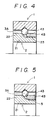
- the inner ring 2 has at one end (in the left in Fig. 4) of its cylindrical body 21 an outwardly extending bracket 21, and the balls 3A or needles placed between the outer ring 1 and the inner ring 2 are retained with a retaining ring 4B.
- Fig. 4 shows the embodiment in which fixing of the retaining ring is made by engagement of screws, and Fig. 5, by adhesion.
- the middle poart 26 of the inner ring extends outwardly with its outside diameter "d o " larger than the inside diameter "d i " of the bracket 12 of the outer ring, and the needles 3B are placed in the space formed between the bulge 26 of the inner ring and the cylindrical body 11 of the outer ring, and retained by the retaining ring 4C.
- the inwardly extending bracket 12 at one end of the outer ring is a ring 4C ⁇ separate from the cylindrical body 11 and fixed by engagement of screws.
- This alternative is, therefore, identical to the bearing in which the needles 3B are retained by two retaining rings 4C screwed on both ends of the cylindrical body 11.
- the retaining ring can be installed on the inner ring as explained in connection with the alternative of Fig. 4.
- the opening between the outer ring and the inner ring can be designed to be relatively wide or tight, or even substantially closed, and should be selected in accordance with the use of the bearing.
- alumina, zirconia, silicon ritride and other materials called "fine ceramics" are preferable, and should be selected in accordance with the use of the bearing.
- the production of the parts can be carried out by mixing fine powder of ceramics with appropriate binder, followed by press work.
- the green (intermediate product) thus obtained can be submitted to screw cutting and formation of V-shaped groove, and finally, to sintering.
- Installation of the retaining ring to the outer ring or the inner ring can be carried out by use of an appropriate adhesive.
- the conventional steel bearings are assembled by shrinkage fit using the high thermal expansion coefficients of metals. Thermal expansion of ceramics is not so large as metals, and the possible elastic deformation is small. Therefore, ceramics bearings cannot be assembled by the conventional method.
- Inventors of this invention have discovered that ceramics materials shaped by utilizing an appropriate binder can be submitted to precision machining and that the machined products can be sintered with uniform shrinkage, thus providing sintered products of precise dimension. Using this method, the inventors established a technology which, for example, can cut a fine pitched external or internal thread and provide sintered products with precise fitting as threads cut on metal materials.
- the inventors succeeded to provide bearings in which all the parts are made of ceramics.
- the ceramic bearings according to this invention have extremely high durability compared with conventional steel bearings. Therefore, they are useful as the parts of machines which are subject to continuous operation for a long period or uses where maintenance are difficult. Characteristics inherent in ceramics materials such as chemical-resistance, acid-resistance, brine-resistance, make the bearings useful in chemical plants and maritime use. Since the bearings are heat-resistant, they are useful as bearings used at such a high temperatures that lubricants are not usable, or even higher temperatures. The advantage of wear-resistance means that the bearings may be suitably applied in such use as casters in clean-room for IC production.
- a small size bearing with the structure illustrated in Figs. 1 and 2 was produced alumina.
- the finished dimension of the parts are designed to be as follows. shaft diameter (inside diameter of the inner ring) 8 mm outside diameter (outside diameter of the outer ring) 10 mm balls-center diameter 13 mm balls diameter 1.5 mm x 25
- All the green was prepared by taking into account of 17% sintering shrinkage, and after sintering, the corner of the inwardly extending bracket of the outer ring and the inside corner of the retaining ring was abrased to form a 60° inclination against the axis.
- a V-shaped groove was also carved on the outside of the inner ring and polished to form 60° inclination each giving a total opening of 120°.
- a shaft was fitted on the inner ring, and the retaining ring was screwed in with adhesive on the screw, and before the adhesive hardens, the retaining ring was screwed in and out to find the minimum torque with a torque meter attached to the outer ring.
- the retaining ring was left at the location where the torque was minimum to allow the adhesive to harden.
- the condition under which the torque to the outer ring minimum is the condition where the V-shaped grooves contacting the balls face each other properly and the bearing is of the best function.
- a small size bearing with the structure illustrated in Fig. 7 was produced with zirconia.
- Dimensions of the parts are as follows.
- a ring in the form of the retaining ring was fixed to the cylindrical body of the outer ring with an adhesive containing zirconia powder to form the bracket.
- the ring got stuck due to the powder on the screw surface, and was left for the adhesive to harden.
- the needles were placed and the retaining ring was screwed in and fixed with the adhesive.
- This bearing displayed good performance as a relatively high load bearing.
Abstract
Description
- The present invention relates to a rolling bearing made of ceramics.
- The new ceramic materials which have become available by recent progress in fine ceramics technology are used, for example, skid-rails in furnaces, taking advantage of their wear-resistant property and low friction coefficient in addition to the familiar features of ceramics, heat-resistant and chemical-resistant.
- On the other hand, the demand for miniaturization and higher performance of industrial and household machines requires that the bearings supporting rotating axles be smaller and lighter and resistant to higher load and higher rotation. Efforts have been made to meet the demand by improving the special alloy used as bearing material and upgrading the machining technology, but satisfactory results are not yet achieved.
- The object of the present invention is, in light of aforementioned present status of the technology, to provide bearings made of ceramic materials having superior property compared with conventional steel bearings.
-
- Fig. 1 and Fig. 2 illustrate an embodiment of the ceramics bearing according to the present invention; Fig 1 being a plan view of one half, and Fig. 2 being a longitudinal sectional view (the other halves are synmetrical to the center line).
- Fig. 3 is an alternative of the embodiment illustrated in Fig. 1 and Fig. 2, and is a sectional view equivalent to Fig. 2.
- Fig. 4 and Fig. 5 illustrate another alternative of the ceramics bearing shown in Figs. 1 and 2, and are sectional view equivalent to Fig. 2.
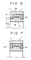
- Fig. 6 illustrates another embodiment of the present invention, and is a sectional view equivalent to Figs. 2-5.
- Fig. 7 illustrates an alternative of the embodiment shown in Fig. 6, and is a sectional view equivalent thereto.
-
- Referring to the drawings, the ceramics bearing of the present invention is explained below in detail.
- The bearing consists of, as shown in Fig. 1 and Fig. 2, an outer ring 1, an
inner ring 2 andballs 3A or needles placed between the outer andinner ring 2 andballs 3A or needles placed between the outer and inner rings, and is characterized in that all the parts of the bearing are made of ceramics, the outer ring 1 has at one end (in the left in Fig. 2) of itscylindrical body 11 an inwardly extendingbracket 12, and that theballs 3A or needles placed between the outer ring 1 and theinner ring 2 are retained with aretaining ring 4A which is fixed inside the outer ring. - In the embodiment shown in Fig. 2, the corner of the
bracket 12 of the outer ring and the corner of theretaining ring 4A each has a inclined surface which together form a groove of a V-shaped cross section, and anothergroove 25 of a V-shaped cross section is provided at the surface of the inner ring facing to the aforesaid groove, and theballs 3A are retainned in the space formed by the interfacing V-shaped grooves. - Fixing of the
retaining ring 4A to the outer ring 1 is, in the illustrated embodiments, achieved by engagement of the screw threaded on the inner surface of the outer ring opposite to the bracked and the screw threaded on the outer surface of theretaining ring 4A. - It is also possible to achieve fixing, as shown in Fig. 3, with a
suitable adhesive 5. - As can be easily understood, the aforementioned retaining ring can be installed on the inner ring instead of the outer ring. In that case, as shown in Fig. 4, the
inner ring 2 has at one end (in the left in Fig. 4) of itscylindrical body 21 an outwardly extendingbracket 21, and theballs 3A or needles placed between the outer ring 1 and theinner ring 2 are retained with aretaining ring 4B. - Fig. 4 shows the embodiment in which fixing of the retaining ring is made by engagement of screws, and Fig. 5, by adhesion.
- In another embodiment of the ceramics bearing of this invention, as shown in Fig 6, the
middle poart 26 of the inner ring extends outwardly with its outside diameter "do" larger than the inside diameter "di" of thebracket 12 of the outer ring, and theneedles 3B are placed in the space formed between thebulge 26 of the inner ring and thecylindrical body 11 of the outer ring, and retained by theretaining ring 4C. - In another alternative of the embodiment shown in Fig. 6, as shown in Fig. 7, the inwardly extending
bracket 12 at one end of the outer ring is a ring 4Cʹ separate from thecylindrical body 11 and fixed by engagement of screws. This alternative is, therefore, identical to the bearing in which theneedles 3B are retained by tworetaining rings 4C screwed on both ends of thecylindrical body 11. - It should be noted that, in the embodiments shown in Fig. 6 and Fig. 7, the retaining ring can be installed on the inner ring as explained in connection with the alternative of Fig. 4.
- There may be various modifications of the ceramics bearing according to this invention. The opening between the outer ring and the inner ring can be designed to be relatively wide or tight, or even substantially closed, and should be selected in accordance with the use of the bearing.
- As for the ceramic materials, alumina, zirconia, silicon ritride and other materials called "fine ceramics" are preferable, and should be selected in accordance with the use of the bearing.
- The production of the parts can be carried out by mixing fine powder of ceramics with appropriate binder, followed by press work. The green (intermediate product) thus obtained can be submitted to screw cutting and formation of V-shaped groove, and finally, to sintering. Installation of the retaining ring to the outer ring or the inner ring can be carried out by use of an appropriate adhesive.
- The conventional steel bearings are assembled by shrinkage fit using the high thermal expansion coefficients of metals. Thermal expansion of ceramics is not so large as metals, and the possible elastic deformation is small. Therefore, ceramics bearings cannot be assembled by the conventional method. Inventors of this invention have discovered that ceramics materials shaped by utilizing an appropriate binder can be submitted to precision machining and that the machined products can be sintered with uniform shrinkage, thus providing sintered products of precise dimension. Using this method, the inventors established a technology which, for example, can cut a fine pitched external or internal thread and provide sintered products with precise fitting as threads cut on metal materials.
- According to the present invention, by assistance of this technology and by employing the method of placing the balls or needles between the outer ring and the inner ring of the bearing and fixing the retaining ring typically by screw engagement, the inventors succeeded to provide bearings in which all the parts are made of ceramics.
- The ceramic bearings according to this invention have extremely high durability compared with conventional steel bearings. Therefore, they are useful as the parts of machines which are subject to continuous operation for a long period or uses where maintenance are difficult. Characteristics inherent in ceramics materials such as chemical-resistance, acid-resistance, brine-resistance, make the bearings useful in chemical plants and maritime use. Since the bearings are heat-resistant, they are useful as bearings used at such a high temperatures that lubricants are not usable, or even higher temperatures. The advantage of wear-resistance means that the bearings may be suitably applied in such use as casters in clean-room for IC production.
- A small size bearing with the structure illustrated in Figs. 1 and 2 was produced alumina. The finished dimension of the parts are designed to be as follows.
shaft diameter (inside diameter of the inner ring) 8 mm
outside diameter (outside diameter of the outer ring) 10 mm
balls-center diameter 13 mm
balls diameter 1.5 mm x 25 - All the green was prepared by taking into account of 17% sintering shrinkage, and after sintering, the corner of the inwardly extending bracket of the outer ring and the inside corner of the retaining ring was abrased to form a 60° inclination against the axis. A V-shaped groove was also carved on the outside of the inner ring and polished to form 60° inclination each giving a total opening of 120°.
- A shaft was fitted on the inner ring, and the retaining ring was screwed in with adhesive on the screw, and before the adhesive hardens, the retaining ring was screwed in and out to find the minimum torque with a torque meter attached to the outer ring. The retaining ring was left at the location where the torque was minimum to allow the adhesive to harden.
- The condition under which the torque to the outer ring minimum is the condition where the V-shaped grooves contacting the balls face each other properly and the bearing is of the best function.
- The adjustment of the retaining ring mentioned above can be of course carried out automatically in a mass production line.
- A small size bearing with the structure illustrated in Fig. 7 was produced with zirconia. Dimensions of the parts are as follows.
shaft diameter (inside diameter of the inner ring) 8 mm
outside diameter of the inner ring (outward bracket) 12.5mm
outside diameter of the outer ring 20 mm
inside diameter of the outer ring 15.5mm
needles diameter 1.5mm x length 5mm x 27 - A ring in the form of the retaining ring was fixed to the cylindrical body of the outer ring with an adhesive containing zirconia powder to form the bracket. The ring got stuck due to the powder on the screw surface, and was left for the adhesive to harden.
- The needles were placed and the retaining ring was screwed in and fixed with the adhesive.
- This bearing displayed good performance as a relatively high load bearing.
Claims (12)
Applications Claiming Priority (2)
| Application Number | Priority Date | Filing Date | Title |
|---|---|---|---|
| JP202936/86 | 1986-08-29 | ||
| JP20293686 | 1986-08-29 |
Publications (2)
| Publication Number | Publication Date |
|---|---|
| EP0258845A2 true EP0258845A2 (en) | 1988-03-09 |
| EP0258845A3 EP0258845A3 (en) | 1988-08-17 |
Family
ID=16465613
Family Applications (1)
| Application Number | Title | Priority Date | Filing Date |
|---|---|---|---|
| EP87112582A Withdrawn EP0258845A3 (en) | 1986-08-29 | 1987-08-28 | Ceramics bearing |
Country Status (1)
| Country | Link |
|---|---|
| EP (1) | EP0258845A3 (en) |
Cited By (15)
| Publication number | Priority date | Publication date | Assignee | Title |
|---|---|---|---|---|
| FR2635566A1 (en) * | 1988-08-22 | 1990-02-23 | Comadur Sa | Ceramic rolling-contact bearing, particularly ball bearing |
| EP0365178A2 (en) * | 1988-10-21 | 1990-04-25 | Isuzu Motors Limited | Bearing structure of rotary machine |
| EP0422786A2 (en) * | 1989-10-12 | 1991-04-17 | Wing Highcera Co., Ltd. | Ceramic bearing |
| DE4011710A1 (en) * | 1990-04-11 | 1991-10-17 | Mtu Muenchen Gmbh | Axial gap between two moving components - is closed by peripheral seal consisting of grooved support ring and sealing lips with balls |
| GB2278650A (en) * | 1993-06-01 | 1994-12-07 | Skf Gmbh | Rolling bearing for high temperature applications |
| US5571760A (en) * | 1993-08-27 | 1996-11-05 | Saint-Gobain/Norton Industrial Ceramics Corporation | Silicon nitride having a high tensile strength |
| WO1996036572A1 (en) * | 1995-05-15 | 1996-11-21 | Rockwool International A/S | Apparatus for the formation of man-made vitreous fibres |
| US5759481A (en) * | 1994-10-18 | 1998-06-02 | Saint-Gobain/Norton Industrial Ceramics Corp. | Silicon nitride having a high tensile strength |
| NL1006534C2 (en) * | 1997-07-10 | 1999-01-12 | Skf Ind Trading & Dev | Asymmetrical angular contact ball bearing. |
| DE102006019982A1 (en) * | 2006-04-29 | 2007-10-31 | Schaeffler Kg | Ball and roller bearing rotary connection for supporting e.g. crane, has single flexible ball race formed in longitudinal section to provide elastic deformation such that roller bearing is prestressed in circumferential area |
| DE102010028421A1 (en) * | 2010-04-30 | 2011-11-03 | Von Ardenne Anlagentechnik Gmbh | Ceramic roller bearing for use in end block of e.g. pipe magnetron arrangement utilized in vacuum coating system for coating substrate, has roller bodies arranged in body cage between inner and outer rings, where rings have partial rings |
| CN104736866A (en) * | 2012-10-24 | 2015-06-24 | Ntn株式会社 | Cylindrical roller bearing |
| JP2018179023A (en) * | 2017-04-03 | 2018-11-15 | イビデン株式会社 | Bearing |
| KR20200030861A (en) * | 2018-09-13 | 2020-03-23 | (주)연합시스템 | Bearing device for crane and high place works vehicles and manufacturing method thereof |
| CN114876965A (en) * | 2022-06-17 | 2022-08-09 | 山东朗澈轴承有限公司 | Be applicable to high load deep groove ball bearing lasso subassembly |
Citations (4)
| Publication number | Priority date | Publication date | Assignee | Title |
|---|---|---|---|---|
| FR1350297A (en) * | 1963-03-06 | 1964-01-24 | Freewheels for cycles or motorcycles with foolproof bearings | |
| US3178241A (en) * | 1963-03-18 | 1965-04-13 | Space Technology And Res Corp | Lubricationless high-temperature bearing |
| DE2028762A1 (en) * | 1969-06-11 | 1970-12-17 | Textron Inc., Providence, R.I. (V.St.A.) | Angular contact |
| EP0158901A1 (en) * | 1984-03-30 | 1985-10-23 | Koyo Seiko Co., Ltd. | Rotating member supporting apparatus |
-
1987
- 1987-08-28 EP EP87112582A patent/EP0258845A3/en not_active Withdrawn
Patent Citations (4)
| Publication number | Priority date | Publication date | Assignee | Title |
|---|---|---|---|---|
| FR1350297A (en) * | 1963-03-06 | 1964-01-24 | Freewheels for cycles or motorcycles with foolproof bearings | |
| US3178241A (en) * | 1963-03-18 | 1965-04-13 | Space Technology And Res Corp | Lubricationless high-temperature bearing |
| DE2028762A1 (en) * | 1969-06-11 | 1970-12-17 | Textron Inc., Providence, R.I. (V.St.A.) | Angular contact |
| EP0158901A1 (en) * | 1984-03-30 | 1985-10-23 | Koyo Seiko Co., Ltd. | Rotating member supporting apparatus |
Cited By (21)
| Publication number | Priority date | Publication date | Assignee | Title |
|---|---|---|---|---|
| FR2635566A1 (en) * | 1988-08-22 | 1990-02-23 | Comadur Sa | Ceramic rolling-contact bearing, particularly ball bearing |
| EP0365178A2 (en) * | 1988-10-21 | 1990-04-25 | Isuzu Motors Limited | Bearing structure of rotary machine |
| EP0365178A3 (en) * | 1988-10-21 | 1991-07-03 | Isuzu Motors Limited | Bearing structure of rotary machine |
| EP0422786A2 (en) * | 1989-10-12 | 1991-04-17 | Wing Highcera Co., Ltd. | Ceramic bearing |
| EP0422786A3 (en) * | 1989-10-12 | 1991-09-11 | Wing Highcera Co., Ltd. | Ceramic bearing |
| DE4011710A1 (en) * | 1990-04-11 | 1991-10-17 | Mtu Muenchen Gmbh | Axial gap between two moving components - is closed by peripheral seal consisting of grooved support ring and sealing lips with balls |
| GB2278650A (en) * | 1993-06-01 | 1994-12-07 | Skf Gmbh | Rolling bearing for high temperature applications |
| US5571760A (en) * | 1993-08-27 | 1996-11-05 | Saint-Gobain/Norton Industrial Ceramics Corporation | Silicon nitride having a high tensile strength |
| US5759481A (en) * | 1994-10-18 | 1998-06-02 | Saint-Gobain/Norton Industrial Ceramics Corp. | Silicon nitride having a high tensile strength |
| WO1996036572A1 (en) * | 1995-05-15 | 1996-11-21 | Rockwool International A/S | Apparatus for the formation of man-made vitreous fibres |
| NL1006534C2 (en) * | 1997-07-10 | 1999-01-12 | Skf Ind Trading & Dev | Asymmetrical angular contact ball bearing. |
| WO1999002873A1 (en) * | 1997-07-10 | 1999-01-21 | Skf Engineering & Research Centre B.V. | Asymmetric angular contact ball bearing |
| DE102006019982A1 (en) * | 2006-04-29 | 2007-10-31 | Schaeffler Kg | Ball and roller bearing rotary connection for supporting e.g. crane, has single flexible ball race formed in longitudinal section to provide elastic deformation such that roller bearing is prestressed in circumferential area |
| DE102010028421A1 (en) * | 2010-04-30 | 2011-11-03 | Von Ardenne Anlagentechnik Gmbh | Ceramic roller bearing for use in end block of e.g. pipe magnetron arrangement utilized in vacuum coating system for coating substrate, has roller bodies arranged in body cage between inner and outer rings, where rings have partial rings |
| DE102010028421B4 (en) * | 2010-04-30 | 2012-02-23 | Von Ardenne Anlagentechnik Gmbh | Ceramic rolling bearing and end block for a rotating magnetron |
| CN104736866A (en) * | 2012-10-24 | 2015-06-24 | Ntn株式会社 | Cylindrical roller bearing |
| US9624977B2 (en) | 2012-10-24 | 2017-04-18 | Ntn Corporation | Cylindrical roller bearing |
| JP2018179023A (en) * | 2017-04-03 | 2018-11-15 | イビデン株式会社 | Bearing |
| KR20200030861A (en) * | 2018-09-13 | 2020-03-23 | (주)연합시스템 | Bearing device for crane and high place works vehicles and manufacturing method thereof |
| CN114876965A (en) * | 2022-06-17 | 2022-08-09 | 山东朗澈轴承有限公司 | Be applicable to high load deep groove ball bearing lasso subassembly |
| CN114876965B (en) * | 2022-06-17 | 2024-02-20 | 山东朗澈轴承有限公司 | Be applicable to high load deep groove ball bearing ring subassembly |
Also Published As
| Publication number | Publication date |
|---|---|
| EP0258845A3 (en) | 1988-08-17 |
Similar Documents
| Publication | Publication Date | Title |
|---|---|---|
| EP0258845A2 (en) | Ceramics bearing | |
| KR910001542B1 (en) | Rollers for rolling mills | |
| EP0381336B1 (en) | Ceramic bearing | |
| AU634735B2 (en) | Ceramic bearing and manufacturing method | |
| US3428374A (en) | Self-lubricating bearing | |
| KR960000986B1 (en) | Ceramic bearing | |
| US5333954A (en) | Rolling/sliding part | |
| US5971620A (en) | Rolling element bearing comprising a zirconium material | |
| US3874680A (en) | Seal ring and bearing assembly | |
| EP0422799B1 (en) | Ceramic bearing | |
| US4876875A (en) | Supported ceramic guide roller | |
| JP2503969B2 (en) | Ceramic bearing and method of manufacturing the same | |
| JPH0320115A (en) | Ceramic bearing | |
| US4754494A (en) | Beryllium based, wear-resistant material for bearings and the like | |
| EP0492605B1 (en) | Shaft sleeve made of ceramics | |
| US3535005A (en) | Bearing construction | |
| EP0422786B1 (en) | Ceramic bearing | |
| US6619847B1 (en) | Ceramic dynamic-pressure bearing, motor having bearing, hard disk drive, and polygon scanner | |
| US4682445A (en) | Ceramic center for machine tools | |
| JPH0410561B2 (en) | ||
| US6948893B2 (en) | Clamping system coated with solid lubricant for machine tools | |
| JPS60220256A (en) | Ball screw | |
| JPH07305727A (en) | Ceramic solid roller and manufacture thereof | |
| JP3773080B2 (en) | Rolling bearing | |
| CA3086540A1 (en) | Corrosion resistant bearing elements, bearing assemblies, bearing apparatuses, and motor assemblies using the same |
Legal Events
| Date | Code | Title | Description |
|---|---|---|---|
| PUAI | Public reference made under article 153(3) epc to a published international application that has entered the european phase |
Free format text: ORIGINAL CODE: 0009012 |
|
| AK | Designated contracting states |
Kind code of ref document: A2 Designated state(s): CH DE FR GB IT LI |
|
| PUAL | Search report despatched |
Free format text: ORIGINAL CODE: 0009013 |
|
| AK | Designated contracting states |
Kind code of ref document: A3 Designated state(s): CH DE FR GB IT LI |
|
| 17P | Request for examination filed |
Effective date: 19890217 |
|
| RAP1 | Party data changed (applicant data changed or rights of an application transferred) |
Owner name: KABUSHIKI KAISHA NAGANO KEIKI SEISAKUSHO |
|
| 17Q | First examination report despatched |
Effective date: 19900306 |
|
| STAA | Information on the status of an ep patent application or granted ep patent |
Free format text: STATUS: THE APPLICATION IS DEEMED TO BE WITHDRAWN |
|
| 18D | Application deemed to be withdrawn |
Effective date: 19910726 |
|
| RIN1 | Information on inventor provided before grant (corrected) |
Inventor name: KUNIFUJI, KAZUO Inventor name: KOBAYASHI, TOSHIO |