EP0258622B2 - Ship's propulsion unit - Google Patents
Ship's propulsion unit Download PDFInfo
- Publication number
- EP0258622B2 EP0258622B2 EP87110850A EP87110850A EP0258622B2 EP 0258622 B2 EP0258622 B2 EP 0258622B2 EP 87110850 A EP87110850 A EP 87110850A EP 87110850 A EP87110850 A EP 87110850A EP 0258622 B2 EP0258622 B2 EP 0258622B2
- Authority
- EP
- European Patent Office
- Prior art keywords
- ship
- engine system
- propeller
- gear unit
- motor
- Prior art date
- Legal status (The legal status is an assumption and is not a legal conclusion. Google has not performed a legal analysis and makes no representation as to the accuracy of the status listed.)
- Expired - Lifetime
Links
- 230000008878 coupling Effects 0.000 claims description 9
- 238000010168 coupling process Methods 0.000 claims description 9
- 238000005859 coupling reaction Methods 0.000 claims description 9
- 239000011796 hollow space material Substances 0.000 claims 2
- 230000005540 biological transmission Effects 0.000 description 9
- 238000009434 installation Methods 0.000 description 7
- 238000010276 construction Methods 0.000 description 3
- 238000007689 inspection Methods 0.000 description 2
- 206010067482 No adverse event Diseases 0.000 description 1
- 230000004308 accommodation Effects 0.000 description 1
- 238000005452 bending Methods 0.000 description 1
- 230000015572 biosynthetic process Effects 0.000 description 1
- 239000000446 fuel Substances 0.000 description 1
- 230000010354 integration Effects 0.000 description 1
- 239000010687 lubricating oil Substances 0.000 description 1
- 238000012423 maintenance Methods 0.000 description 1
- 238000004519 manufacturing process Methods 0.000 description 1
- 239000012528 membrane Substances 0.000 description 1
- 238000007789 sealing Methods 0.000 description 1
Images


Classifications
-
- B—PERFORMING OPERATIONS; TRANSPORTING
- B63—SHIPS OR OTHER WATERBORNE VESSELS; RELATED EQUIPMENT
- B63H—MARINE PROPULSION OR STEERING
- B63H21/00—Use of propulsion power plant or units on vessels
- B63H21/30—Mounting of propulsion plant or unit, e.g. for anti-vibration purposes
-
- B—PERFORMING OPERATIONS; TRANSPORTING
- B63—SHIPS OR OTHER WATERBORNE VESSELS; RELATED EQUIPMENT
- B63H—MARINE PROPULSION OR STEERING
- B63H23/00—Transmitting power from propulsion power plant to propulsive elements
- B63H23/02—Transmitting power from propulsion power plant to propulsive elements with mechanical gearing
- B63H23/06—Transmitting power from propulsion power plant to propulsive elements with mechanical gearing for transmitting drive from a single propulsion power unit
-
- F—MECHANICAL ENGINEERING; LIGHTING; HEATING; WEAPONS; BLASTING
- F02—COMBUSTION ENGINES; HOT-GAS OR COMBUSTION-PRODUCT ENGINE PLANTS
- F02B—INTERNAL-COMBUSTION PISTON ENGINES; COMBUSTION ENGINES IN GENERAL
- F02B3/00—Engines characterised by air compression and subsequent fuel addition
- F02B3/06—Engines characterised by air compression and subsequent fuel addition with compression ignition
Definitions
- the invention relates to a marine machine system with a medium-speed diesel engine driving the propeller shaft via a transmission.
- Single-acting, slow-running two-stroke diesel engines are characterized by very low fuel consumption and are therefore considered to be relatively inexpensive prime movers.
- the speeds are on average around 100 rpm, so that a direct connection to the waveguide is possible.
- the difficulties in accommodating the large and heavy slow-moving engines led to the development of medium-speed, single-acting four-stroke diesel engines that are built as in-line or V-engines. Their speeds are on average about 500 rpm and require a gearbox to reduce the engine speed to the propeller speed.
- the medium-speed diesel engines are primarily intended to solve the difficulties caused by the limitation of the installation space due to the sharpening of the aft ship.
- the invention is based on the object of creating an even more compact design for an inexpensive installation option in the aft ship.
- the aim is to arrange the drive machine further than was previously possible in the direction of the propeller in the aft ship.
- the invention for solving this problem is characterized by the features specified in the characterizing part of patent claim 1. This results in a particularly compact design with even smaller dimensions, so that the engine can be returned to the rear ship further than before.
- the propeller intermediate shaft area can be used for the motor arrangement, since the length of the motor corresponds approximately to an intermediate wavelength and this is returned below the motor.
- the installation weights are low.
- an adjustable box can be provided on the front of the propeller intermediate shaft.
- the large wheel hub is provided with a cylindrical cavity, the diameter of which is larger than the diameter of the aligned axial bores of the propeller intermediate shaft and the peg-shaped extension of the wheel hub.
- This cavity can serve, for example, to accommodate further elements that can be removed before the radial expansion of the large wheel.
- the formation of the cylindrical cavity is achieved in a simple manner in that the pin-shaped extension of the wheel hub is screwed as a separate section to the large wheel, the large wheel having a conventional hollow hub and being screwed evenly to the intermediate shaft flange. As a result, the cavity is delimited on one end face by the intermediate shaft flange and on the opposite end face by the peg-shaped extension of the wheel hub.
- This training has manufacturing and assembly advantages. Another advantage of the assembly in the confined spaces results from an arrangement of the thrust bearing transmitting the propeller thrust in the transmission.
- the thrust washer can be arranged on the pin-shaped extension of the wheel hub and the pressure segments can be stored in the transmission housing.
- the large wheel After removing the drive pinion and lifting off the top part of the housing, the large wheel can be lifted radially as soon as the fastening screws are loosened. This means that the expansion and subsequent installation work can also be carried out at sea, even with the limited space in the aft ship, using on-board equipment.
- the motor 1 is connected to the propeller 2, the propeller shaft 3 and the propeller intermediate shaft 4 via a reduction gear 5, which is located on the front of the motor.
- the motor shaft is connected to a drive flange 7a of a flange shaft 7 via a motor output flange 6.
- the flange shaft 7 passes through a drive hollow shaft 8 with the drive pinion 9.
- the flange shaft is supported within the hollow shaft 8 with the aid of a bearing 8a.
- the flange shaft 7 carries a torsionally flexible coupling 10, which transmits the torque to the hollow shaft 8 via the flange disk 10a.
- the large wheel 17 is supported on both sides by bearings 15 and 16.
- a further support bearing 14 is provided on the propeller-side drive unit for the intermediate shaft 4.
- the gear housing consists of a lower part 13 and, for installation reasons, a two-part upper gear part 11, 12.
- the bearing housing lower part 18 on the rear engine side is integrated into the lower part 13 of the gear housing. Only the bearing housing part 19 is attached.
- the propeller thrust is transmitted to the thrust bearing 22 via the shaft pressure ring 21.
- the gear housing lower part 13 forms a unit with the base frame 30 of the motor. From there, the propeller thrust is introduced into the ship's foundation.
- the intermediate shaft 4 carries a flange 20 and is screwed to the propeller shaft 3.
- Deviating in the presentation acc. Fig. 3 is a power take-off 23 for a marine auxiliary machine, not shown.
- the auxiliary drive wheel 24 on the hollow shaft 8 of the main drive pinion transmits the torque to the auxiliary drive pinion 25 of a power take-off shaft 26, which can be connected, for example, to a generator.
- the thrust bearing for receiving the propeller thrust for forward and reverse travel is located outside the actual reduction gear, but exactly aligned with it, since the trough of the thrust bearing and the Gear housing forms a unit.
- a shaft misalignment as a result of misaligned bearings, bending or twisting of the foundation or the hull therefore have no adverse effects within the motor gear block.
- the variant according to FIGS. 5 and 11 shows the arrangement of the thrust bearing 27, 28, 41, 42 directly next to the large wheel of the transmission.
- the motor foundations are firmly connected to the combined gear-thrust bearing housing.
- a cardanic coupling 34 is installed, which drives the hollow shaft 8 of the drive pinion 9 via the flange shaft 7 and the torsionally flexible coupling 10.
- the flange shaft 7 is supported both in the cardanic coupling 34 and via a spherical bearing 35 and a support plate 10b via the elastic coupling 10 to the hollow drive shaft 8.
- the large wheel 17 is fastened to a flange 4a of the propeller intermediate shaft 4 by screws 36.
- the wheel hub shows a peg-shaped extension 17 a, which is supported in the housing bearing 16.
- an axial cavity extends through the propeller intermediate shaft 4 and the peg-shaped extension 17a of the large wheel hub, which extends from the bores 38 in FIG Propeller intermediate shaft and 39 the large wheel hub.
- a linkage 37 of an adjustable propeller extends through the axial cavity and extends into an adjusting device 40 on the transmission housing 12, 13.
- the embodiment according to FIG. 10 shows an alternative embodiment.
- the pin-shaped hub extension 17a is separated from the large wheel 17 and is only screwed to it.
- the large wheel is designed with a conventional hollow hub 41.
- the diameter of the hub bore is larger than the diameter of the axial bores 38 and 39 for receiving the actuating linkage for the variable pitch propeller.
- the cavity 42 is delimited on the end face by the flange 4a of the propeller intermediate shaft and the peg-shaped extension 17a of the large wheel hub.
- the pin-shaped extension 17b of the wheel hub carries the thrust washer 41, flanked by the pressure segments 42 mounted in the gear housing 12, 13.
- the hub extension 17b has a greater axial extension than the examples according to FIGS. 8 to 10. If this is the case, too Linkage 37 and adjustment device 40, as indicated by the broken line, installed, these parts must be removed in the axial direction to the machine room side before removing the large wheel 17.
- the pressure segments can be removed or installed through an opening provided in the gear housing or after the two-part housing has been separated.
Landscapes
- Chemical & Material Sciences (AREA)
- Engineering & Computer Science (AREA)
- Combustion & Propulsion (AREA)
- Mechanical Engineering (AREA)
- Ocean & Marine Engineering (AREA)
- General Details Of Gearings (AREA)
Description
Die Erfindung betrifft eine Schiffsmaschinenanlage mit einem die Propellerwelle über ein Getriebe antreibenden mittelschnell laufenden Dieselmotor.The invention relates to a marine machine system with a medium-speed diesel engine driving the propeller shaft via a transmission.
Einfach wirkende, langsam laufende Zweitakt-Dieselmotoren zeichnen sich durch einen sehr niedrigen Brennstoffverbrauch aus und gelten daher als verhältnismäßig günstige Antriebsmaschinen. Die Unterbringung und Befestigung dieser großen und schweren Motoren sowie die Beherrschung der Vibrationen sind jedoch vielfach schiffbaulich schwierig. Die Drehzahlen liegen im Mittel bei etwa 100 U/min, so daß eine direkte Verbindung mit der Wellenleitung möglich ist. Die Schwierigkeiten bei der Unterbringung der großen und schweren Langsamläufer führten zur Entwicklung mittelschnell laufender, einfach wirkender Viertakt-Dieselmotoren, die als Reihen- oder V-Motoren gebaut werden. Ihre Drehzahlen betragen im Mittel etwa 500 U/min und erfordern ein Getriebe zur Reduzierung der Motordrehzahl auf die Propellerdrehzahl. Mit den mittelschnell laufenden Dieselmotoren sollen vor allem die Schwierigkeiten, die durch die Beschränkung des Einbauraums infolge derZuschärfung des Achterschiffs gegeben sind, behoben werden. Ausgehend von einer solchen Anlage liegt der Erfindung die Aufgabe zu Grunde, eine noch kompaktere Bauweise für eine günstige Einbaumöglichkeit im Achterschiffzu schaffen. Insbesondere soll erreicht werden, die Antriebsmaschine weiter als es bisher möglich war, in Richtung auf den Propellerversetzt im Achterschiff anzuordnen.Single-acting, slow-running two-stroke diesel engines are characterized by very low fuel consumption and are therefore considered to be relatively inexpensive prime movers. However, the accommodation and mounting of these large and heavy engines as well as the control of the vibrations are often difficult in shipbuilding. The speeds are on average around 100 rpm, so that a direct connection to the waveguide is possible. The difficulties in accommodating the large and heavy slow-moving engines led to the development of medium-speed, single-acting four-stroke diesel engines that are built as in-line or V-engines. Their speeds are on average about 500 rpm and require a gearbox to reduce the engine speed to the propeller speed. The medium-speed diesel engines are primarily intended to solve the difficulties caused by the limitation of the installation space due to the sharpening of the aft ship. Starting from such a system, the invention is based on the object of creating an even more compact design for an inexpensive installation option in the aft ship. In particular, the aim is to arrange the drive machine further than was previously possible in the direction of the propeller in the aft ship.
Die Erfindung zur Lösung dieser Aufgabe zeichnet sich durch die im kennzeichnenden Teil des Patentanspruchs 1 angegebenen Merkmale aus. Dadurch wird eine besonders kompakte Bauweise mit noch geringeren Abmessungen erzielt, so daß der Motor weiter als bisher in das Hinterschiff zurückgestellt werden kann.The invention for solving this problem is characterized by the features specified in the characterizing part of
Vorteilhaft ist, daß der Propeller-Zwischenwellenbereich für die Motoranordnung ausgenutzt werden kann, da die Länge des Motors in etwa einer Zwischenwellenlänge entspricht und diese unterhalb des Motors zurückgeführt ist. Die Installationsgewichte sind gering. Für einen Verstellpropeller kann eine Verstellbox auf der Vorderseite der Propellerzwischenwelle vorgesehen werden. Gegenüber den langsam laufenden Zweitaktmotoren, mit denen die vorliegende Ausführung bezüglich der Fundamentaufstellung technisch vergleichbar ist, sind die genannten Vorteile, die noch durch die einfachere Wartung mittelschnell laufender Dieselmotoren ergänzt werden, besonders gravierend.It is advantageous that the propeller intermediate shaft area can be used for the motor arrangement, since the length of the motor corresponds approximately to an intermediate wavelength and this is returned below the motor. The installation weights are low. For an adjustable propeller, an adjustable box can be provided on the front of the propeller intermediate shaft. Compared to the slow-running two-stroke engines, with which the present version is technically comparable with regard to the foundation set-up, the advantages mentioned, which are supplemented by the easier maintenance of medium-speed diesel engines, are particularly serious.
Weitere, den Erfindungsgegenstand vorteilhaft gestaltende Merkmale sind vorgesehen, um insbesondere bei Drehzahländerungen, Inspektionen oder Havarien einen radialen Ein-und Ausbau des Getriebegroßrades aus dem Getriebegehäuse zu ermöglichen. Von besonderem Vorteil ist es, wenn die Großradnabe mit einem zylindrischen Hohlraum versehen wird, dessen Durchmesser größer ist als der Durchmesser der fluchtenden Axialbohrungen von Propellerzwischenwelle und zapfenförmiger Verlängerung der Radnabe. Dieser Hohlraum kann beispielsweise zur Aufnahme weiterer, vor dem radialen Ausbau des Großrades demontierbarer Elemente dienen.Further features that advantageously shape the subject matter of the invention are provided, in order to enable radial installation and removal of the large gear wheel from the gear housing, in particular in the event of changes in speed, inspections or accidents. It is particularly advantageous if the large wheel hub is provided with a cylindrical cavity, the diameter of which is larger than the diameter of the aligned axial bores of the propeller intermediate shaft and the peg-shaped extension of the wheel hub. This cavity can serve, for example, to accommodate further elements that can be removed before the radial expansion of the large wheel.
Die Ausbildung des zylindrischen Hohlraumes wird in einfacher Weise dadurch erreicht, daß die zapfenförmige Verlängerung der Radnabe als getrenntes Teilstück mit dem Großrad verschraubt ist, wobei das Großrad eine übliche Hohlnabe aufweist und selbst an dem Zwischenwellenflansch festgeschraubt ist. Dadurch wird der Hohlraum an einer Stirnseite von dem Zwischenwellenflansch und an der dieser gegenüberliegenden Stirnseite von der zapfenförmigen Verlängerung der Radnabe begrenzt. Diese Ausbildung hat herstellungstechnische und montagemäßige Vorteile. Ein weiterer Montagevorteil bei den beengten Raumverhältnissen ergibt sich bei einer Anordnung des den Propellerschub übertragenden Drucklagers im Getriebe. Hierfür können die Druckscheibe auf der zapfenförmigen Verlängerung der Radnabe angeordnet und die Drucksegmente im Getriebegehäuse gelagert werden.The formation of the cylindrical cavity is achieved in a simple manner in that the pin-shaped extension of the wheel hub is screwed as a separate section to the large wheel, the large wheel having a conventional hollow hub and being screwed evenly to the intermediate shaft flange. As a result, the cavity is delimited on one end face by the intermediate shaft flange and on the opposite end face by the peg-shaped extension of the wheel hub. This training has manufacturing and assembly advantages. Another advantage of the assembly in the confined spaces results from an arrangement of the thrust bearing transmitting the propeller thrust in the transmission. For this purpose, the thrust washer can be arranged on the pin-shaped extension of the wheel hub and the pressure segments can be stored in the transmission housing.
Das Großrad kann nach der Demontage des Antriebsritzels und Abheben des Gehäuseoberteils radial herausgehoben werden, sobald die Befestigungsschrauben gelöst sind. Der Ausbau und die anschließenden Einbauarbeiten können dadurch selbst bei den beengten Raumverhältnissen im Achterschiff mit Bordmitteln auch auf See durchgeführt werden.After removing the drive pinion and lifting off the top part of the housing, the large wheel can be lifted radially as soon as the fastening screws are loosened. This means that the expansion and subsequent installation work can also be carried out at sea, even with the limited space in the aft ship, using on-board equipment.
In der Zeichnung sind einige Ausführungsbeispiele der Erfindung schematisch dargestellt und nachstehend erläutert.In the drawing, some embodiments of the invention are shown schematically and explained below.
Es zeigen:
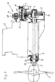
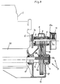
- Fig. 1 eine Motoranordnung mit einem Drucklager auf der Propellerseite der Antriebseinheit,
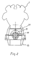
- Fig. 2 eine Ansicht der hinteren Stirnseite des Motors gem. Fig. 1,
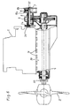
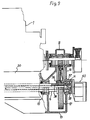
- Fig. 3 eine Motoranordnung mit einem zusätzlichen Nebenabtrieb für eine Schiffshilfsmaschine,
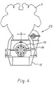
- Fig. 4 eine Ansicht der hinteren Stirnseite des Motors gem. Fig. 3,
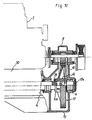
- Fig. 5 eine Anordnung gemäß Fig. 1 mit der Anordnung des Drucklagers auf der Motorvorderseite,
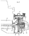
- Fig. 6 eine Anordnung des Motors gemäß Fig. 1 mit einer elastischen Motorbefestigung auf seinem Fundament,
- Fig. 7 eine Ansicht der hinteren Stirnseite des Motors gem. Fig. 6 mit einer Ausschnittsvergrößerung im Bereich der elastischen Motorbefestigung,
- Fig. 8 den Längsschnitt durch das Untersetzungsgetriebe mit einem angeflanschten Großrad,
- Fig. 9 die Ausführung der Großradbefestigung gemäß Fig. 8, jedoch mit durch die Propellerzwischenwelle und die Großradnabe geführten Bohrungen zur Aufnahme eines Betätigungsgestänges für einen Verstellpropeller,
- Fig. 10 die Befestigung des Großrades zwischen der Propellerzwischenwelle und dem separat angeordneten zapfenförmigen Verlängerungsstück der Großradnabe zur Bildung eines zylindrischen Hohlraumes und
- Fig. 11 die Ausbildung des Großrades gemäß Fig. 9, jedoch mit der Anordnung des Propellerwellendrucklagers innerhalb des Getriebes.
- 1 shows a motor arrangement with a thrust bearing on the propeller side of the drive unit,
- Fig. 2 is a view of the rear end of the engine acc. Fig. 1,
- 3 shows an engine arrangement with an additional power take-off for a ship auxiliary machine,
- Fig. 4 is a view of the rear end of the engine acc. Fig. 3
- 5 shows an arrangement according to FIG. 1 with the arrangement of the thrust bearing on the front of the engine,
- 6 shows an arrangement of the motor according to FIG. 1 with an elastic motor fastening on its foundation,
- Fig. 7 is a view of the rear end of the engine acc. 6 with an enlarged detail in the area of the elastic motor fastening,
- 8 shows the longitudinal section through the reduction gear with a flanged large wheel,
- 9 shows the design of the large wheel attachment according to FIG. 8, but with bores through the propeller intermediate shaft and the large wheel hub for receiving an actuating linkage for a variable pitch propeller,
- Fig. 10 shows the attachment of the large wheel between the propeller intermediate shaft and the separately arranged pin-shaped extension piece of the large wheel hub to form a cylindrical cavity and
- 11 shows the design of the large wheel according to FIG. 9, but with the arrangement of the propeller shaft thrust bearing within the transmission.
Der Motor 1 ist mit dem Propeller 2, die Propellerwelle 3 und die Propellerzwischenwelle 4 über ein Untersetzungsgetriebe 5 verbunden, das sich auf der Motorvorderseite befindet. Die Motorwelle ist übereinen Motorabtriebsflansch 6 mit einem Antriebsflansch 7a einer Flanschwelle 7 verbunden. Die Flanschwelle 7 durchsetzt eine Antriebshohlwelle 8 mit dem Antriebsritzel 9. Die Flanschwelle ist innerhalb der Hohlwelle 8 mit Hilfe eines Lagers 8a abgestützt. An seinem Ende trägt die Flanschwelle 7 eine drehelastische Kupplung 10, welche das Drehmoment über die Flanschscheibe 10a auf die Hohlwelle 8 überträgt. Das Großrad 17 ist zu beiden Seiten durch Lager 15 und 16 abgestützt. An der propellerseitigen Antriebseinheit ist für die Zwischenwelle 4 ein weiteres Stützlager 14 vorgesehen.The
Das Getriebegehäuse besteht aus einem Unterteil 13 und aus einbautechnischen Gründen aus einem zweiteiligen Getriebeoberteil 11, 12. Das Lagergehäuseunterteil 18 an der hinteren Motorseite ist in das Getriebegehäuseunterteil 13 integriert. Aufgesetzt ist lediglich das Lagergehäuseteil 19. Der Propellerschub wird über den Wellendruckring 21 auf das Drucklager 22 übertragen. Das Getriebegehäuseunterteil 13 bildet mit dem Untergestell 30 des Motors eine Einheit. Der Propellerschub wird von dort in das Schiffsfundament eingeleitet. Die Zwischenwelle 4 trägt einen Flansch 20 und ist mit der Propellerwelle 3 verschraubt.The gear housing consists of a
Bei allen Darstellungen sind die gleichen Teile mit den gleichen Bezugsziffern versehen.
Abweichend bei der Darstellung gem. Fig. 3 ist ein Nebenabtrieb 23 für eine nicht dargestellte Schiffshilfsmaschine. Das Nebenantriebsrad 24 auf der Hohlwelle 8 des Hauptantriebsritzels überträgt das Drehmoment auf das Nebenantriebsritzel 25 einer Nebenabtriebswelle 26, die beispielsweise mit einem Generator verbunden sein kann.In all representations, the same parts are provided with the same reference numbers.
Deviating in the presentation acc. Fig. 3 is a power take-
Bei dem Antriebskonzept nach den Figuren 1, 3, 6, 8, 9 und 10 befindet sich das Drucklager zur Aufnahme des Propellerschubs für die Vorwärts- und Rückwärtsfahrt außerhalb des eigentlichen Untersetzungsgetriebes, jedoch genau fluchtend zu diesem, da die Wanne des Drucklager- und des Getriebegehäuses eine Einheit bildet. Ein Wellenversatz infolge nicht fluchtender Lagerungen, Durchbiegungen bzw. Verwindungen des Fundamentes oder des Schiffskörpers haben daher keine nachteiligen Einflüsse innerhalb des Motor-Getriebeblocks.In the drive concept according to Figures 1, 3, 6, 8, 9 and 10, the thrust bearing for receiving the propeller thrust for forward and reverse travel is located outside the actual reduction gear, but exactly aligned with it, since the trough of the thrust bearing and the Gear housing forms a unit. A shaft misalignment as a result of misaligned bearings, bending or twisting of the foundation or the hull therefore have no adverse effects within the motor gear block.
Gegenüber den vorgenannten Figuren zeigt die Variante nach den Figuren 5 und 11 die Anordnung des Drucklagers 27, 28, 41, 42 unmittelbar neben dem Großrad des Getriebes. Eine solche Lösung bietet sich dann an, wenn propellerseitig nicht genügend Raum für die Anordnung eines Drucklagers und dessen Inspektionsmöglichkeit gegeben ist. Bei den Ausführungen nach den Figuren 1 bis 5 und 8 bis 11 sind die Motorenfundamente fest mit dem kombinierten Getriebe-Drucklagergehäuse verbunden. Die Integrierung von Motor- Getriebe -Kupplung - Drucklager innerhalb eines Bausystems unter Ausnutzung der Motorlänge für die Dimensionierung und Lagerung der Propellerwelle schafft nicht nur erhebliche wirtschaftliche Vorteile bei der Installation im Maschinenraum, sondern auch wichtige technische bei der Ausbildung des Fundamentes des gesamten Antriebsblocks.Compared to the aforementioned figures, the variant according to FIGS. 5 and 11 shows the arrangement of the
Für bestimmte Schiffsausführungen ist es erforderlich, den Antriebsmotor mit seinem Gehäusefußflansch 29 auf seinem Untergestell 30 elastisch zu befestigen. Um die elastische Fundamentierung auch bei dem beschriebenen Antriebsblock durchführen zu können, wird, wie in Figuren 6, 7 dargestellt, der Motor in Längsrichtung an jeder Seite durch mehrere elastische Lagerelemente 31 auf dem Untergestell 30 befestigt. Eine Winkelleiste 32 in Verbindung mit einer elastischen Membrandichtung 33 sorgt für die notwendige Abdichtung gegen Eintritt von Fremdstoffen jeglicher Art in das Getriebe-Drucklagergehäuse und gegen den Austritt von Schmieröl. Hier bei ist es außerdem erforderlich, die Verbindung zwischen dem Motor und dem Antriebsritzel des Getriebes abweichend von der Konstruktion der Figuren 1 bis 5 und 8 bis 11 auszuführen. Zwischen dem Motorabtriebsflansch und Antriebsflansch 7a der Flanschwelle wird beispielsweise eine kardanische Kupplung 34 eingebaut, die über die Flanschwelle 7 und die drehelastische Kupplung 10 die Hohlwelle 8 des Antriebsritzels 9 antreibt. Hierbei wird die Flanschwelle 7 sowohl in der kardanischen Kupplung 34 als auch über ein sphärisch ausgebildetes Lager 35 und eine Stützscheibe 10b überdie elastische Kupplung 10 zur Antriebshohlwelle 8 abgestützt.For certain ship designs, it is necessary to fasten the drive motor elastically with its
Bei der Ausführung nach den Figuren 8 bis 11 ist das Großrad 17 an einem Flansch 4a der Propellerzwischenwelle 4 durch Schrauben 36 befestigt. Die Radnabe zeigt eine zapfenförmige Verlängerung 17a, die im Gehäuselager 16 abgestützt ist. Praktisch die gleiche Ausführung des Großrades zeigt die Figur 9, jedoch mit dem Unterschied, daß sich durch die Propellerzwischenwelle 4 und die zapfenförmige Verlängerung 17a der Großradnabe ein axialer Hohlraum erstreckt, der sich aus den Bohrungen 38 der Propellerzwischenwelle und 39 der Großradnabe zusammensetzt. Durch den axialen Hohlraum erstreckt sich ein Gestänge 37 eines Verstellpropellers, das in eine Verstelleinrichtung 40 am Getriebegehäuse 12, 13 reicht.In the embodiment according to FIGS. 8 to 11, the
Eine alternative Ausführungsform zeigt die Ausbildung nach Fig. 10. Die zapfenförmige Nabenverlängerung 17a ist vom Großrad 17 getrennt und lediglich mit diesem verschraubt. Zu diesem Zweck ist das Großrad mit einer üblichen Hohlnabe 41 ausgeführt. Der Durchmesser der Nabenbohrung ist größer als die Durchmesser der axialen Bohrungen 38 und 39 zur Aufnahme des Betätigungsgestänges für den Verstellpropeller. Der Hohlraum 42 wird stirnseitig von dem Flansch 4a der Propellerzwischenwelle und der zapfenförmigen Verlängerung 17a der Großradnabe begrenzt. Diese Befestigungskonstruktion bietet die Möglichkeit, weitere, demontierbare Getriebeelemente platzsparend innerhalb der Großradnabe anzuordnen.The embodiment according to FIG. 10 shows an alternative embodiment. The pin-shaped
Zur Demontage des Großrades nach den Fig. 8 und 10 ist es nach dem Abheben des Getriebegehäuseoberteils lediglich notwendig, die Befestigungsschrauben 36 zwischen der Radnabe und der Propellerzwischenwelle 4 zu lösen, so daß die Arbeiten erforderlichenfalls auch bei den beengten Platzverhältnissen auf See mit Bordmitteln durchgeführt werden können. Werden die Propellerzwischenwelle 4 und die Radnabe entsprechend Fig. 9 von einem Betätigungsgestänge für einen Verstell propeller durchsetzt, so ist zunächst nach dem Lösen der Verstelleinrichtung 40 vom Getriebegehäuse das Betätigungsgestänge 37 in Axialrichtung so weit zu verschieben, bis eine radiale Bewegung des gelösten Großrades ermöglicht wird. Auch die Ausführung nach Fig. 11, welche die Anordnung des Propellerwellendrucklagers im Getriebe zeigt, läßt sich sowohl für Fest- als auch Verstellpropeller verwenden. Die zapfenförmige Verlängerung 17b der Radnabe trägt hierbei die Druckscheibe 41, flankiert von den im Getriebegehäuse 12, 13 gelagerten Drucksegmenten 42. Die Nabenverlängerung 17b weist zu diesem Zweck eine größere axiale Erstreckung auf als die Beispiele nach den Figuren 8 bis 10. Falls auch hier ein Gestänge 37 und Verstellgerät 40, wie durch die unterbrochene Strichführung angedeutet, eingebaut ist, müssen diese Teile vor dem Ausbau des Großrades 17 in Achsrichtung zur Maschinenraumseite hin ausgebaut werden. Um beim radialen Ein-und Ausbau des Großrades genügend axiale Freiheit zu erhalten, können die Drucksegmente durch eine im Getriebegehäuse vorgesehene Öffnung bzw. nach Trennung des zweiteiligen Gehäuses aus- bzw. eingebaut werden.To disassemble the large wheel according to FIGS. 8 and 10, after lifting off the upper part of the gear housing it is only necessary to loosen the fastening screws 36 between the wheel hub and the propeller
Claims (12)
Applications Claiming Priority (4)
| Application Number | Priority Date | Filing Date | Title |
|---|---|---|---|
| DE3628385 | 1986-08-25 | ||
| DE19863628385 DE3628385A1 (en) | 1986-08-25 | 1986-08-25 | Marine engine layout |
| DE3710792 | 1987-03-31 | ||
| DE3710792 | 1987-03-31 |
Publications (3)
| Publication Number | Publication Date |
|---|---|
| EP0258622A1 EP0258622A1 (en) | 1988-03-09 |
| EP0258622B1 EP0258622B1 (en) | 1990-01-17 |
| EP0258622B2 true EP0258622B2 (en) | 1993-03-03 |
Family
ID=25846740
Family Applications (1)
| Application Number | Title | Priority Date | Filing Date |
|---|---|---|---|
| EP87110850A Expired - Lifetime EP0258622B2 (en) | 1986-08-25 | 1987-07-27 | Ship's propulsion unit |
Country Status (4)
| Country | Link |
|---|---|
| EP (1) | EP0258622B2 (en) |
| DE (1) | DE3761420D1 (en) |
| ES (1) | ES2012475B3 (en) |
| FI (1) | FI873660A7 (en) |
Families Citing this family (4)
| Publication number | Priority date | Publication date | Assignee | Title |
|---|---|---|---|---|
| US5242785A (en) * | 1987-06-25 | 1993-09-07 | Fuji Photo Film Co., Ltd. | Silver halide color photographic material containing color stain inhibitors and discoloring inhibitors |
| DE3930514A1 (en) * | 1989-09-13 | 1991-03-21 | Renk Tacke Gmbh | Propulsion unit for ship - is located on carrier, supported by hull via elastic element to prevent transmission of vibration |
| CN114147479A (en) * | 2021-12-02 | 2022-03-08 | 武汉理工大学 | Centering tool, system and method for intermediate shaft system of full-rotation propeller |
| CN115009499B (en) * | 2022-06-17 | 2024-06-11 | 沪东中华造船(集团)有限公司 | Lock shaft disc centering method and lock shaft disc device |
Family Cites Families (2)
| Publication number | Priority date | Publication date | Assignee | Title |
|---|---|---|---|---|
| US4383829A (en) * | 1979-10-25 | 1983-05-17 | Great Lakes Power Products, Inc. | Drive assembly for inboard speedboat |
| SE454432B (en) * | 1985-06-26 | 1988-05-02 | Volvo Penta Ab | SUSPENSION SYSTEM FOR A DRIVER |
-
1987
- 1987-07-27 ES ES87110850T patent/ES2012475B3/en not_active Expired - Lifetime
- 1987-07-27 EP EP87110850A patent/EP0258622B2/en not_active Expired - Lifetime
- 1987-07-27 DE DE8787110850T patent/DE3761420D1/en not_active Expired - Lifetime
- 1987-08-24 FI FI873660A patent/FI873660A7/en not_active Application Discontinuation
Also Published As
| Publication number | Publication date |
|---|---|
| FI873660L (en) | 1988-02-26 |
| FI873660A7 (en) | 1988-02-26 |
| DE3761420D1 (en) | 1990-02-22 |
| FI873660A0 (en) | 1987-08-24 |
| ES2012475B3 (en) | 1990-04-01 |
| EP0258622A1 (en) | 1988-03-09 |
| EP0258622B1 (en) | 1990-01-17 |
Similar Documents
| Publication | Publication Date | Title |
|---|---|---|
| EP0853577B1 (en) | Ship drive with a driving engine and a directly driven propeller shaft | |
| DE3348400C2 (en) | Inboard outboard drive | |
| DE69319620T2 (en) | PROPELLER DRIVE | |
| DE60118157T2 (en) | MOTOR UNIT FOR SHIPS | |
| DE3046679C2 (en) | Branch gear for a ship propulsion | |
| DE3620648A1 (en) | CONNECTING DEVICE FOR A REAR DRIVE OF A WATER VEHICLE | |
| EP0258622B2 (en) | Ship's propulsion unit | |
| EP0140010B1 (en) | Ship's propulsion plant | |
| DE10063338B4 (en) | Device for propelling a ship | |
| DE2939760A1 (en) | SHIP PROPELLER UNIT | |
| DE19729046A1 (en) | Ship propulsion with a prime mover and a directly driven propeller shaft | |
| EP3793893B1 (en) | Drive system for a ship | |
| DE3930514A1 (en) | Propulsion unit for ship - is located on carrier, supported by hull via elastic element to prevent transmission of vibration | |
| DE2805688C2 (en) | Propulsion device for a small watercraft | |
| EP1069043A2 (en) | Ship propulsion with two-motor drive | |
| EP1134160A2 (en) | Ship propulsion with diesel or electric motors | |
| DE3628385A1 (en) | Marine engine layout | |
| DE8716109U1 (en) | Ship's machinery | |
| DE3700584C2 (en) | ||
| DE4230500C2 (en) | Arrangement of a wave generator system on board ships | |
| DE19900003C2 (en) | Boat propulsion, especially outboard propulsion | |
| EP1099624B1 (en) | Ship propulsion with geared single engine | |
| DE202006010783U1 (en) | Power pack installation for powerboat consists of hull-mounted motor housing with integral prop shaft supports | |
| DE3839086A1 (en) | Arrangement for transmitting thrust between a rudder propeller and the hull of a vessel | |
| EP0030597A1 (en) | Internal combustion engine with injection pumps arrangement |
Legal Events
| Date | Code | Title | Description |
|---|---|---|---|
| PUAI | Public reference made under article 153(3) epc to a published international application that has entered the european phase |
Free format text: ORIGINAL CODE: 0009012 |
|
| AK | Designated contracting states |
Kind code of ref document: A1 Designated state(s): DE ES FR GB IT NL |
|
| 17P | Request for examination filed |
Effective date: 19880414 |
|
| 17Q | First examination report despatched |
Effective date: 19890608 |
|
| ITF | It: translation for a ep patent filed | ||
| GRAA | (expected) grant |
Free format text: ORIGINAL CODE: 0009210 |
|
| AK | Designated contracting states |
Kind code of ref document: B1 Designated state(s): DE ES FR GB IT NL |
|
| PG25 | Lapsed in a contracting state [announced via postgrant information from national office to epo] |
Ref country code: GB Effective date: 19900117 Ref country code: FR Effective date: 19900117 |
|
| REF | Corresponds to: |
Ref document number: 3761420 Country of ref document: DE Date of ref document: 19900222 |
|
| GBT | Gb: translation of ep patent filed (gb section 77(6)(a)/1977) | ||
| ET | Fr: translation filed | ||
| PLBI | Opposition filed |
Free format text: ORIGINAL CODE: 0009260 |
|
| 26 | Opposition filed |
Opponent name: CARL HURTH MASCHINEN- UND ZAHNRADFABRIK GMBH & CO. Effective date: 19900801 |
|
| NLR1 | Nl: opposition has been filed with the epo |
Opponent name: CARL HURTH MASCHINEN- UND ZAHNRADFABRIK GMBH & CO. |
|
| ITTA | It: last paid annual fee | ||
| PG25 | Lapsed in a contracting state [announced via postgrant information from national office to epo] |
Ref country code: NL Effective date: 19920303 |
|
| PGFP | Annual fee paid to national office [announced via postgrant information from national office to epo] |
Ref country code: ES Payment date: 19920721 Year of fee payment: 6 |
|
| PGFP | Annual fee paid to national office [announced via postgrant information from national office to epo] |
Ref country code: GB Payment date: 19920722 Year of fee payment: 6 |
|
| PGFP | Annual fee paid to national office [announced via postgrant information from national office to epo] |
Ref country code: FR Payment date: 19920723 Year of fee payment: 6 |
|
| PGFP | Annual fee paid to national office [announced via postgrant information from national office to epo] |
Ref country code: NL Payment date: 19920731 Year of fee payment: 6 |
|
| PUAH | Patent maintained in amended form |
Free format text: ORIGINAL CODE: 0009272 |
|
| STAA | Information on the status of an ep patent application or granted ep patent |
Free format text: STATUS: PATENT MAINTAINED AS AMENDED |
|
| 27A | Patent maintained in amended form |
Effective date: 19930303 |
|
| AK | Designated contracting states |
Kind code of ref document: B2 Designated state(s): DE ES FR GB IT NL |
|
| NLR2 | Nl: decision of opposition | ||
| EN3 | Fr: translation not filed ** decision concerning opposition | ||
| NLV1 | Nl: lapsed or annulled due to failure to fulfill the requirements of art. 29p and 29m of the patents act | ||
| GBV | Gb: ep patent (uk) treated as always having been void in accordance with gb section 77(7)/1977 [no translation filed] |
Effective date: 19900117 |
|
| PG25 | Lapsed in a contracting state [announced via postgrant information from national office to epo] |
Ref country code: ES Free format text: LAPSE BECAUSE OF THE APPLICANT RENOUNCES Effective date: 19940728 |
|
| PGFP | Annual fee paid to national office [announced via postgrant information from national office to epo] |
Ref country code: DE Payment date: 19980618 Year of fee payment: 12 |
|
| REG | Reference to a national code |
Ref country code: ES Ref legal event code: FD2A Effective date: 19991007 |
|
| PG25 | Lapsed in a contracting state [announced via postgrant information from national office to epo] |
Ref country code: DE Free format text: LAPSE BECAUSE OF NON-PAYMENT OF DUE FEES Effective date: 20000601 |
|
| PG25 | Lapsed in a contracting state [announced via postgrant information from national office to epo] |
Ref country code: IT Free format text: LAPSE BECAUSE OF NON-PAYMENT OF DUE FEES;WARNING: LAPSES OF ITALIAN PATENTS WITH EFFECTIVE DATE BEFORE 2007 MAY HAVE OCCURRED AT ANY TIME BEFORE 2007. THE CORRECT EFFECTIVE DATE MAY BE DIFFERENT FROM THE ONE RECORDED. Effective date: 20050727 |