EP0257552B1 - Television signal selection device - Google Patents
Television signal selection device Download PDFInfo
- Publication number
- EP0257552B1 EP0257552B1 EP87112049A EP87112049A EP0257552B1 EP 0257552 B1 EP0257552 B1 EP 0257552B1 EP 87112049 A EP87112049 A EP 87112049A EP 87112049 A EP87112049 A EP 87112049A EP 0257552 B1 EP0257552 B1 EP 0257552B1
- Authority
- EP
- European Patent Office
- Prior art keywords
- channel
- frequency
- frequency band
- television signal
- signal
- Prior art date
- Legal status (The legal status is an assumption and is not a legal conclusion. Google has not performed a legal analysis and makes no representation as to the accuracy of the status listed.)
- Expired - Lifetime
Links
Images


Classifications
-
- H—ELECTRICITY
- H04—ELECTRIC COMMUNICATION TECHNIQUE
- H04N—PICTORIAL COMMUNICATION, e.g. TELEVISION
- H04N5/00—Details of television systems
- H04N5/44—Receiver circuitry for the reception of television signals according to analogue transmission standards
- H04N5/50—Tuning indicators; Automatic tuning control
Definitions
- This invention relates to a television signal selection device in a television receiver for automatically searching for a proper video signal or for promptly leading a received signal into a proper state.
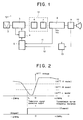
- Fig. 1 is a block arrangement diagram of a television signal receiving set.
- This receiving set comprises an antenna 1, an RF amplifier 2, a local oscillator and mixer 3, a PLL circuit and prescaler 4, a microcomputer for channel selection 5, a SAW filter 6, an adjacent voice trap 7, a video signal demodulator 8, a video signal processor 9, a CRT 10, and a video signal detector 13.
- Numeral 11 designates an AFT voltage output which is applied from the video signal demodulator 8 to the channel selecting microcomputer 5, and numeral 12 a video signal detection output which is provided from the video signal detector 13.
- the SAW filter 6 and the adjacent voice trap 7 constitute a SAW filter with an adjacent voice trap characteristic.
- Fig. 2 shows the characteristics of an AFT voltage (a voltage for automatic reception frequency tuning) and a television signal detection output versus a transmission carrier frequency deviation in a television receiver which has a system (hereinbelow, termed "pseudo-synchronous demodulation system") hitherto often used wherein a video carrier is sampled by a resonance coil to perform the quadrature demodulation of a video intermediate-frequency signal.
- the resonance characteristic of the video carrier is comparatively gentle. Therefore, even for transmission frequency deviations in, for example, the HRC or ICC format of CATV broadcast in U. S. A., the optimum reception state could be established in such a way that the PLL circuit and prescaler 4 shown in Fig.
- a frequency range for search be a regular transmission frequency ⁇ 2 MHz
- a received television signal is presumed to lie in a range from a deviation -f1 to +2 MHz if the television signal detection output at the reception of the point of a transmission frequency deviation of zero is "high,” and it is presumed to lie in a range from the deviation -f1 to -2 MHz or to be quite nonexistent if the detection output is "low.”
- the television signal Once the television signal has been detected, it can be thereafter led to the optimum reception frequency according to the characteristic curve of the AFT voltage versus the transmission carrier frequency deviation. This operation is illustrated in a flow chart of Fig. 4.
- the received frequency is raised from the previous frequency every ⁇ f along the path of a loop l1.
- the received frequency is lowered every ⁇ f along the path of a loop l2.
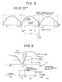
- Fig. 3 shows the frequency correlation of video, chroma and sound carriers in a transmitted television signal, and the overall response characteristic of the video intermediate-frequency circuit of a television receiver receiving the transmitted signal, including a lower-side adjacent voice signal trap.
- the television receiving set in the prior art is constructed as described above, and can search for the television signal comparatively easily.
- it has had the problem that a long time is required in case of deciding the absence of a proper video signal in a frequency band for search or in case of receiving a signal extremely spaced from the regular reception frequency.
- requests for a higher picture quality and a higher tonal quality have recently been made, and a system (hereinbelow, termed "complete synchronous demodulation system”) is adopted wherein the video carrier for the quadrature demodulation is generated using a PLL in the video signal demodulator 8 shown in Fig. 1. Since, however, the lock-in range of the PLL exists in this case, a prior-art system illustrated in Figs. 2 - 4 has been incapable of appropriately receiving the television signal in a case where the television signal lies in the frequency region departing from the lock-in range and where the frequency region is a frequency region to be searched.
- GP-A-2 094 080 discloses a television signal receiving set with the features including in the first part of claim 1.
- the object of the present invention is to provide a television signal receiving set which can search reliably and promptly for a television signal even in different television standards.
- the television signal selection device uses unit frequency bands dividing the frequency range of a television signal of the channel to be searched, wherein the lower limit frequency of the unit frequency bands is determined by the voice trap frequency of the channel being lower adjacent to the current channel and the higher limit frequency is dictated by the PLL lock-in range of the video signal demodulator as shown in Fig. 5.
- the unit frequency bands of the frequency range are searched sequentially from the upper to the lower frequency band by checking the video signal detection output and the AFT voltage output.
- the check result is stored as a position data indicating the unit search frequency band including the video carrier signal of the channel.
- the upper limit of the unit frequency bands of the invention may be lower than the frequency determined by the PLL lock-in range of the video signal demodulator and is not exactly defined, whereas the lower-limit frequency determined by the voice trap characteristic of the lower-side adjacent channel is definitely fixed to a point which is 1.25 MHz lower than a regular video carrier frequency. Accordingly, when the frequency band of a television signal to be searched is divided into unit frequency bands which are then searched from the upper side, the presence or absence of a television signal can be reliably analysed gradually from the upper side without being affected by a video signal which will appear in due course.
- the information on the video current signal obtained from the aforesaid search is stored as a position data indicative for frequency values of the unit search band in which the video carrier signal was detected during the automatic channel pre-setting operation.
- the stored information can be applied to discriminate a detected signal as a spurious signal ascribable to the voice signal of the adjacent lower-side channel or used at a time at which the particular channel is selected again.
- Fig. 1 is a block arrangement diagram of a television signal receiver in which a section from a signal input stage to a video signal demodulation output is shown in detail.
- Fig. 2 is a diagram in which the AFT voltage of a video intermediate-frequency circuit employing a pseudo-synchronous demodulator and the television detection output are shown versus the transmission carrier deviation, and as an expedient for selecting the point of the transmission carrier deviation of zero, AFT output voltages are divided into three regions to set H, M and L modes in the order of higher AFT.
- Fig. 3 shows the frequency correlation of video, chroma and sound carriers in a transmitted television signal, and the overall response characteristic of the video intermediate-frequency circuit of the television receiver receiving the signal, including a lower-side adjacent voice signal trap.
- Fig. 4 is a flow chart for the pull-in of a proper signal based on a television signal search system in a prior art.
- Fig. 5 is a diagram in which the AFT voltage of a video intermediate-frequency circuit employing a complete synchronous demodulator and the detection output of a television signal are shown versus the transmission carrier deviation, and the regions of the H, M and L modes of AFT are set.
- Fig. 6 shows the shift of the intermediate-frequency overall response, as well as the attendant changes of the AFT voltage and the television signal detection output, at the time at which a reception frequency is changed by a PLL circuit and a prescaler 4, a channel selecting microcomputer 5, and a local oscillator and mixer 3 in order to catch a video signal P3 in a case where the whole search band in each channel is composed of three unit search frequency bands.
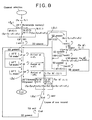
- Figs. 7 and 8 are flow charts in the automatic channel presetting mode and channel selecting mode of the device of this invention, respectively.
- Figs. 7 and 8 are state transition diagrams, and Figs. 5 and 6 show an AFT voltage and a television signal detection output in a unit search frequency band.
- Fig. 7 is the state transition diagram in the case of executing an automatic channel presetting mode.
- SD indicates the television signal detection output
- M(1, 1), M(1, 0) and M(0, 1) indicate the respective positions of parts obtained when the whole search frequency band is divided in three from the upper side thereof by the use of the unit search frequency band shown in Fig. 5.
- M(0, 0) is employed for indicating a case where a proper video signal has not been found in any unit search frequency band by the search.
- M′ denotes a working memory which temporarily stores each search mode state
- f c denotes the regular video carrier frequency of a selected channel
- f0 denotes a working video reception frequency for executing each search mode.
- the reception frequency is set at (f c + ⁇ F1 + ⁇ F2) which is higher than the original frequency of the regular reception channel by the unit search frequency band, whereupon the detection output SD is checked.
- This state corresponds to (I) in Fig. 6. Since the signal P3 does not exist in this band, it is decided that the detection output SD is absent, and the processing in Fig. 7 proceeds in a direction l1. That is, the reception frequency is set at the frequency f c which is assigned to the regular reception channel. This state corresponds to (II) in Fig. 6.
- the signal P3 does not exist in this band, either, "SD absent” is decided, and a reception frequency (f c - ⁇ F1 - ⁇ F2) is selected in order to receive the final unit search frequency band. Since the signal P3 exists in this band as shown at (III) in Fig. 6, "SD present” is decided, and information (0, 1) is stored in the memory M′. Thereafter, the reception frequency is finely tuned every ⁇ f in accordance with processing l2 until the AFT voltage becomes the M mode. As a result, the information of the memory M′ is stored in a nonvolatile memory.
- processing l3 is a process in which a spurious signal ascribable to an adjacent lower-side voice signal is discriminated on the basis of the information M of the last-selected channel and the information M′ being the result of the channel search at this time.
- the information M′ obtained by the search at this time is applied at the first stage of the search of the next channel and is utilized for the prompt video signal search.
- Fig. 8 shows an example of the state transition diagram in the case where the information items M of the unit search frequency bands once stored in the nonvolatile memory are utilized at the (manual) selection of a channel.
- the information in the preceding search is called out of the nonvolatile memory by processing l5, and the reception frequency is separately set at (f c - ⁇ F1 - ⁇ F2), f c or (f c + ⁇ F1 + ⁇ F2) in accordance with the content of the information.
- the television signal detection output SD is checked.
- processing l6 corrects the maximum reception frequency deviations + ⁇ F1 and - ⁇ F2 within the unit search frequency bands by utilizing the AFT voltages and establishes the proper reception state.
- processing l7 which is similar to the processing l1 in Fig. 7.
- the appearance of the detection output SD is waited in each of the unit search frequency bands called out of the nonvolatile memory at the channel selecting manipulation, and processing l8 for entering the processing l6 or l7 again is executed simultaneously with the appearance.
- a frequency band to be searched within a channel is divided using a unit search frequency band whose lower limit and upper limit are set, and the divided bands are checked from the upper side toward the lower side by video signal detection means and AFT voltage generation means, thereby to detect a proper video signal, so that the presence or absence of a television signal can be detected reliably and promptly.
- the information of the video signal obtained by the search is stored as the position data of the unit search frequency band where the video signal for the frequency band to be searched has been detected, it can be applied to the discrimination of a spurious video signal attributed to the voice signal of an adjacent lower-side channel appearing in an adjacent upper-side channel or to the utilization of the signal-present unit search frequency band information at the time at which the particular channel is selected again.
Description
- This invention relates to a television signal selection device in a television receiver for automatically searching for a proper video signal or for promptly leading a received signal into a proper state.
- Fig. 1 is a block arrangement diagram of a television signal receiving set. This receiving set comprises an
antenna 1, anRF amplifier 2, a local oscillator andmixer 3, a PLL circuit andprescaler 4, a microcomputer forchannel selection 5, aSAW filter 6, anadjacent voice trap 7, avideo signal demodulator 8, avideo signal processor 9, aCRT 10, and avideo signal detector 13.Numeral 11 designates an AFT voltage output which is applied from thevideo signal demodulator 8 to thechannel selecting microcomputer 5, and numeral 12 a video signal detection output which is provided from thevideo signal detector 13. TheSAW filter 6 and theadjacent voice trap 7 constitute a SAW filter with an adjacent voice trap characteristic. - Fig. 2 shows the characteristics of an AFT voltage (a voltage for automatic reception frequency tuning) and a television signal detection output versus a transmission carrier frequency deviation in a television receiver which has a system (hereinbelow, termed "pseudo-synchronous demodulation system") hitherto often used wherein a video carrier is sampled by a resonance coil to perform the quadrature demodulation of a video intermediate-frequency signal. In the above system, the resonance characteristic of the video carrier is comparatively gentle. Therefore, even for transmission frequency deviations in, for example, the HRC or ICC format of CATV broadcast in U. S. A., the optimum reception state could be established in such a way that the PLL circuit and
prescaler 4 shown in Fig. 1 was controlled using a decision at the reception of a regular reception frequency as stated below. Assuming in Fig. 2 that a frequency range for search be a regular transmission frequency ±2 MHz, a received television signal is presumed to lie in a range from a deviation -f₁ to +2 MHz if the television signal detection output at the reception of the point of a transmission frequency deviation of zero is "high," and it is presumed to lie in a range from the deviation -f₁ to -2 MHz or to be quite nonexistent if the detection output is "low." Once the television signal has been detected, it can be thereafter led to the optimum reception frequency according to the characteristic curve of the AFT voltage versus the transmission carrier frequency deviation. This operation is illustrated in a flow chart of Fig. 4. If the television signal is detected upon the selection of the regular reception frequency fo by the PLL circuit, the received frequency is raised from the previous frequency every Δf along the path of a loop ℓ₁. In contrast, if the television signal is not detected, the received frequency is lowered every Δf along the path of a loop ℓ₂. Thus, it is possible to arrive at the optimum reception state in which the television signal exists and in which the AFT is in an M mode. - Fig. 3 shows the frequency correlation of video, chroma and sound carriers in a transmitted television signal, and the overall response characteristic of the video intermediate-frequency circuit of a television receiver receiving the transmitted signal, including a lower-side adjacent voice signal trap.
- The television receiving set in the prior art is constructed as described above, and can search for the television signal comparatively easily. However, it has had the problem that a long time is required in case of deciding the absence of a proper video signal in a frequency band for search or in case of receiving a signal extremely spaced from the regular reception frequency. Meanwhile, requests for a higher picture quality and a higher tonal quality have recently been made, and a system (hereinbelow, termed "complete synchronous demodulation system") is adopted wherein the video carrier for the quadrature demodulation is generated using a PLL in the
video signal demodulator 8 shown in Fig. 1. Since, however, the lock-in range of the PLL exists in this case, a prior-art system illustrated in Figs. 2 - 4 has been incapable of appropriately receiving the television signal in a case where the television signal lies in the frequency region departing from the lock-in range and where the frequency region is a frequency region to be searched. - From JP-A-59-152717 a channel selection circuit is known which enables a quick search of the AFT signal of a TV channel by shifting the local oscillating frequency in steps through the frequency range of the channel.
- GP-A-2 094 080 discloses a television signal receiving set with the features including in the first part of
claim 1. - The object of the present invention is to provide a television signal receiving set which can search reliably and promptly for a television signal even in different television standards.
- This object is solved by a television signal receiving set according to
claim 1. - Preferred embodiments of the invention are disclosed in the subclaims.
- The television signal selection device according to the present invention uses unit frequency bands dividing the frequency range of a television signal of the channel to be searched, wherein the lower limit frequency of the unit frequency bands is determined by the voice trap frequency of the channel being lower adjacent to the current channel and the higher limit frequency is dictated by the PLL lock-in range of the video signal demodulator as shown in Fig. 5. The unit frequency bands of the frequency range are searched sequentially from the upper to the lower frequency band by checking the video signal detection output and the AFT voltage output. In addition, the check result is stored as a position data indicating the unit search frequency band including the video carrier signal of the channel.
- The upper limit of the unit frequency bands of the invention may be lower than the frequency determined by the PLL lock-in range of the video signal demodulator and is not exactly defined, whereas the lower-limit frequency determined by the voice trap characteristic of the lower-side adjacent channel is definitely fixed to a point which is 1.25 MHz lower than a regular video carrier frequency. Accordingly, when the frequency band of a television signal to be searched is divided into unit frequency bands which are then searched from the upper side, the presence or absence of a television signal can be reliably analysed gradually from the upper side without being affected by a video signal which will appear in due course.
- Moreover, the information on the video current signal obtained from the aforesaid search is stored as a position data indicative for frequency values of the unit search band in which the video carrier signal was detected during the automatic channel pre-setting operation. The stored information can be applied to discriminate a detected signal as a spurious signal ascribable to the voice signal of the adjacent lower-side channel or used at a time at which the particular channel is selected again.
- Fig. 1 is a block arrangement diagram of a television signal receiver in which a section from a signal input stage to a video signal demodulation output is shown in detail.
- Fig. 2 is a diagram in which the AFT voltage of a video intermediate-frequency circuit employing a pseudo-synchronous demodulator and the television detection output are shown versus the transmission carrier deviation, and as an expedient for selecting the point of the transmission carrier deviation of zero, AFT output voltages are divided into three regions to set H, M and L modes in the order of higher AFT.
- Fig. 3 shows the frequency correlation of video, chroma and sound carriers in a transmitted television signal, and the overall response characteristic of the video intermediate-frequency circuit of the television receiver receiving the signal, including a lower-side adjacent voice signal trap.
- Fig. 4 is a flow chart for the pull-in of a proper signal based on a television signal search system in a prior art.
- Fig. 5 is a diagram in which the AFT voltage of a video intermediate-frequency circuit employing a complete synchronous demodulator and the detection output of a television signal are shown versus the transmission carrier deviation, and the regions of the H, M and L modes of AFT are set.
- Fig. 6 shows the shift of the intermediate-frequency overall response, as well as the attendant changes of the AFT voltage and the television signal detection output, at the time at which a reception frequency is changed by a PLL circuit and a
prescaler 4, achannel selecting microcomputer 5, and a local oscillator andmixer 3 in order to catch a video signal P₃ in a case where the whole search band in each channel is composed of three unit search frequency bands. - Figs. 7 and 8 are flow charts in the automatic channel presetting mode and channel selecting mode of the device of this invention, respectively.
- Now, an embodiment of this invention will be described with reference to the drawings. The block arrangement of the device is as illustrated in Fig. 1. Figs. 7 and 8 are state transition diagrams, and Figs. 5 and 6 show an AFT voltage and a television signal detection output in a unit search frequency band. First, Fig. 7 is the state transition diagram in the case of executing an automatic channel presetting mode. In the figure, SD indicates the television signal detection output, and M(1, 1), M(1, 0) and M(0, 1) indicate the respective positions of parts obtained when the whole search frequency band is divided in three from the upper side thereof by the use of the unit search frequency band shown in Fig. 5. Besides, M(0, 0) is employed for indicating a case where a proper video signal has not been found in any unit search frequency band by the search. In addition M′ denotes a working memory which temporarily stores each search mode state, fc denotes the regular video carrier frequency of a selected channel, and f₀ denotes a working video reception frequency for executing each search mode.
- An expedient for searching for a video signal existent at P₃ in Fig. 6 will be described along the flow of Fig. 7. First, the reception frequency is set at (fc + ΔF₁ + ΔF₂) which is higher than the original frequency of the regular reception channel by the unit search frequency band, whereupon the detection output SD is checked. This state corresponds to (I) in Fig. 6. Since the signal P₃ does not exist in this band, it is decided that the detection output SD is absent, and the processing in Fig. 7 proceeds in a direction ℓ₁. That is, the reception frequency is set at the frequency fc which is assigned to the regular reception channel. This state corresponds to (II) in Fig. 6. Since the signal P₃ does not exist in this band, either, "SD absent" is decided, and a reception frequency (fc - ΔF₁ - ΔF₂) is selected in order to receive the final unit search frequency band. Since the signal P₃ exists in this band as shown at (III) in Fig. 6, "SD present" is decided, and information (0, 1) is stored in the memory M′. Thereafter, the reception frequency is finely tuned every Δf in accordance with processing ℓ₂ until the AFT voltage becomes the M mode. As a result, the information of the memory M′ is stored in a nonvolatile memory. Here, processing ℓ₃ is a process in which a spurious signal ascribable to an adjacent lower-side voice signal is discriminated on the basis of the information M of the last-selected channel and the information M′ being the result of the channel search at this time. Besides, as indicated at ℓ₄, the information M′ obtained by the search at this time is applied at the first stage of the search of the next channel and is utilized for the prompt video signal search.
- Next, Fig. 8 shows an example of the state transition diagram in the case where the information items M of the unit search frequency bands once stored in the nonvolatile memory are utilized at the (manual) selection of a channel. First, the information in the preceding search is called out of the nonvolatile memory by processing ℓ₅, and the reception frequency is separately set at (fc - ΔF₁ - ΔF₂), fc or (fc + ΔF₁ + ΔF₂) in accordance with the content of the information. Thereafter, the television signal detection output SD is checked. In the presence of the detection output SD, processing ℓ₆ corrects the maximum reception frequency deviations +ΔF₁ and -ΔF₂ within the unit search frequency bands by utilizing the AFT voltages and establishes the proper reception state. On the other hand, in the absence of the detection output SD, the flow enters processing ℓ₇, which is similar to the processing ℓ₁ in Fig. 7. Further, in a case where the proper video signal has not been detected as the result of the processing ℓ₅ - ℓ₇, the appearance of the detection output SD is waited in each of the unit search frequency bands called out of the nonvolatile memory at the channel selecting manipulation, and processing ℓ₈ for entering the processing ℓ₆ or ℓ₇ again is executed simultaneously with the appearance.
- As described above, according to this invention, a frequency band to be searched within a channel is divided using a unit search frequency band whose lower limit and upper limit are set, and the divided bands are checked from the upper side toward the lower side by video signal detection means and AFT voltage generation means, thereby to detect a proper video signal, so that the presence or absence of a television signal can be detected reliably and promptly. Moreover, since the information of the video signal obtained by the search is stored as the position data of the unit search frequency band where the video signal for the frequency band to be searched has been detected, it can be applied to the discrimination of a spurious video signal attributed to the voice signal of an adjacent lower-side channel appearing in an adjacent upper-side channel or to the utilization of the signal-present unit search frequency band information at the time at which the particular channel is selected again.
Claims (5)
- A television signal receiving set comprising
AFT voltage generation means (6, 7, 8) operating as a frequency discriminator for generating a tuning voltage for automatic adjustment of a receiving frequency of a television channel;
means (13) for detecting a video carrier signal in a received television signal;
a tuning device for finely controlling the reception frequency of the channel; and
a television signal selection device (5);
characterised in that
said tuning device (4) is a frequency synthesiser tuner employing a PLL circuit; and
said television signal selection device (5) comprises means for performing an automatic channel pre-setting operation by dividing the frequency range of the television signal of each channel into unit frequency bands, each having a frequency band width including the frequency discriminator characteristic of said AFT voltage generating means (6, 7, 8), wherein the lower limit frequency of the unit frequency bands is determined by the lower-side voice trap frequency appearing in the overall video intermediate frequency response of said channel, said means for performing the channel presetting operation further comprising means for determining the unit frequency band within the frequency range of the television signal of each channel including the video carrier signal and means for storing a position data of said unit frequency band within the frequency range, wherein the frequency band width including the frequency discriminator from a lower to a higher frequency range and the unit frequency bands within each frequency range are searched sequentially from the upper to the lower frequency band by said means for performing the channel presetting. - The television signal receiving set according to claim 1, wherein said means for performing an automatic channel pre-setting operation carries out the search for the video carrier signal of the current channel first in the unit frequency band whose position data corresponds to the position data of the unit frequency band which includes the video carrier signal of the channel being lower adjacent to the current channel.
- The television signal receiving set according to claim 1 or 2, wherein said means for performing an automatic channel pre-setting operation further comprises means for discriminating a signal detected in the frequency range of the current channel as a spurious signal on the basis of the position data of the unit frequency band including the video carrier signal of the channel being lower adjacent to the current channel and the position data of the unit frequency band including the detected signal in the current channel.
- The television signal receiving set according to any of claims 1 to 3, wherein said television signal selection device (5) further includes means for reading out the unit frequency band of a desired channel determined and stored through said automatic channel pre-setting operation, said means causing the means for performing an automatic channel pre-setting operation to operate when the video carrier signal is not detected in said stored unit frequency band.
- The television signal receiving set according to claim 4, wherein said means for reading out the unit frequency band of a desired channel stands-by until the video carrier signal appears in said stored unit frequency band, if no video carrier signal is detected by the means for performing an automatic channel pre-setting operation.
Applications Claiming Priority (2)
| Application Number | Priority Date | Filing Date | Title |
|---|---|---|---|
| JP195997/86 | 1986-08-20 | ||
| JP61195997A JP2685744B2 (en) | 1986-08-20 | 1986-08-20 | TV signal selection device |
Publications (3)
| Publication Number | Publication Date |
|---|---|
| EP0257552A2 EP0257552A2 (en) | 1988-03-02 |
| EP0257552A3 EP0257552A3 (en) | 1989-10-25 |
| EP0257552B1 true EP0257552B1 (en) | 1995-03-22 |
Family
ID=16350505
Family Applications (1)
| Application Number | Title | Priority Date | Filing Date |
|---|---|---|---|
| EP87112049A Expired - Lifetime EP0257552B1 (en) | 1986-08-20 | 1987-08-19 | Television signal selection device |
Country Status (5)
| Country | Link |
|---|---|
| US (1) | US4819069A (en) |
| EP (1) | EP0257552B1 (en) |
| JP (1) | JP2685744B2 (en) |
| CA (1) | CA1266336A (en) |
| DE (1) | DE3751181T2 (en) |
Families Citing this family (11)
| Publication number | Priority date | Publication date | Assignee | Title |
|---|---|---|---|---|
| US4959872A (en) * | 1988-06-23 | 1990-09-25 | Kabushiki Kaisha Toshiba | Automatic frequency control apparatus for FM receivers |
| KR920009681B1 (en) * | 1989-05-26 | 1992-10-22 | 삼성전자 주식회사 | Method for shorting scanning time of channel |
| JP2844690B2 (en) * | 1989-07-11 | 1999-01-06 | ソニー株式会社 | AFT circuit |
| KR920009877B1 (en) * | 1990-04-28 | 1992-11-02 | 삼성전자 주식회사 | Fast afc sync-method |
| KR950001574B1 (en) * | 1992-02-29 | 1995-02-25 | 삼성전자주식회사 | Hrc mode receiving time reduction method of catv |
| KR960004515B1 (en) * | 1993-06-08 | 1996-04-06 | 엘지전자주식회사 | Auto selecting range expantion apparatus & method of tv |
| SG49798A1 (en) * | 1993-06-30 | 1998-06-15 | Funai Electric Co | Receiving tv station selection unit of tv-vtr |
| JP3572210B2 (en) * | 1998-12-14 | 2004-09-29 | アルプス電気株式会社 | Automatic fine tuning control voltage generation circuit |
| JP3538056B2 (en) * | 1999-02-17 | 2004-06-14 | 株式会社ケンウッド | Digital TV broadcast receiving channel selecting device, receiving device, and channel selecting method |
| JP4752113B2 (en) * | 2001-01-16 | 2011-08-17 | ソニー株式会社 | Electronic device and signal transmission method |
| JP4690019B2 (en) * | 2004-11-18 | 2011-06-01 | リーダー電子株式会社 | Channel detection device and tuner inspection device provided with the same |
Family Cites Families (13)
| Publication number | Priority date | Publication date | Assignee | Title |
|---|---|---|---|---|
| US4038689A (en) * | 1976-06-14 | 1977-07-26 | Matsushita Electric Corporation Of America | Frequency synthesizer tuning system with manual fine tuning control |
| US4262364A (en) * | 1978-02-27 | 1981-04-14 | Tokyo Shibaura Denki Kabushiki Kaisha | Electronic digital channel-selecting apparatus |
| JPS6057768B2 (en) * | 1978-04-21 | 1985-12-17 | 株式会社東芝 | Electronic channel selection device |
| US4302778A (en) * | 1980-06-30 | 1981-11-24 | Zenith Radio Corporation | AFT-wide automatic frequency control system and method |
| GB2094080B (en) * | 1981-02-18 | 1984-11-07 | Sony Corp | Automatic fine tuning circuits for television receivers |
| JPS57143988A (en) * | 1981-03-03 | 1982-09-06 | Fujitsu General Ltd | Reception state detecting circuit of television receiver |
| US4429415A (en) * | 1981-11-30 | 1984-01-31 | Rca Corporation | Signal-seeking tuning system with signal loss protection for a television receiver |
| JPS59152717A (en) * | 1983-02-18 | 1984-08-31 | Sony Corp | Channel selecting circuit of pll frequency synthesizer system |
| JPS59178013A (en) * | 1983-03-29 | 1984-10-09 | Pioneer Electronic Corp | Method for selecting channel of receiver |
| US4498191A (en) * | 1983-06-06 | 1985-02-05 | General Electric Company | Digital automatic frequency control with tracking |
| JPS6077512A (en) * | 1983-10-05 | 1985-05-02 | Pioneer Electronic Corp | Aft circuit of pll synthesizer system television receiver |
| JPH0783288B2 (en) * | 1984-12-29 | 1995-09-06 | ソニー株式会社 | Electronic tuning tuner automatic tuning method |
| US4689685A (en) * | 1986-01-31 | 1987-08-25 | Rca Corporation | Television tuning system with AFT provisions |
-
1986
- 1986-08-20 JP JP61195997A patent/JP2685744B2/en not_active Expired - Fee Related
-
1987
- 1987-07-30 US US07/079,324 patent/US4819069A/en not_active Expired - Lifetime
- 1987-08-04 CA CA000543718A patent/CA1266336A/en not_active Expired - Lifetime
- 1987-08-19 DE DE3751181T patent/DE3751181T2/en not_active Expired - Fee Related
- 1987-08-19 EP EP87112049A patent/EP0257552B1/en not_active Expired - Lifetime
Also Published As
| Publication number | Publication date |
|---|---|
| EP0257552A3 (en) | 1989-10-25 |
| JPS6351777A (en) | 1988-03-04 |
| DE3751181T2 (en) | 1995-07-27 |
| DE3751181D1 (en) | 1995-04-27 |
| EP0257552A2 (en) | 1988-03-02 |
| JP2685744B2 (en) | 1997-12-03 |
| CA1266336A (en) | 1990-02-27 |
| US4819069A (en) | 1989-04-04 |
Similar Documents
| Publication | Publication Date | Title |
|---|---|---|
| US4776038A (en) | Automatic air/cable mode selection apparatus for a television tuner | |
| US4763195A (en) | Television tuning system with provisions for quickly locating active cable channels | |
| CA1288860C (en) | Television tuning system with provisions for tuning rf signals with scrambled video information | |
| EP0257552B1 (en) | Television signal selection device | |
| US6636727B2 (en) | Phase locked loop system | |
| US6864926B2 (en) | Channel tuning apparatus | |
| US5771080A (en) | Television signal tuning device | |
| US4868892A (en) | Tuning system with provisions for calculating the local oscillator frequency from an aft characteristic | |
| US5170497A (en) | Tuning method and apparatus | |
| JP2715347B2 (en) | Synchronization system | |
| US4163259A (en) | Windowed tuning system with synchronous detector | |
| JP3712867B2 (en) | Television receiver channel selection system | |
| KR100322583B1 (en) | Fast channel discovery method and device | |
| JPH01130630A (en) | Rds receiver | |
| JPH0564094A (en) | Tuning device for television receiver | |
| KR950007721Y1 (en) | Improved channel search tunning system in tvcr | |
| JP2003101388A (en) | Digital broadcasting channel selector and method for selecting channel of digital broadcasting | |
| JP2512922B2 (en) | Tuning circuit | |
| KR970006979B1 (en) | Method for automatic channel selection for a receiver | |
| JPH06205314A (en) | Channel selection device | |
| KR960006828B1 (en) | Auto channel search apparatus & method | |
| KR920003022Y1 (en) | Automatic selecting circuit between secam-l and pal-b/g | |
| JP3306002B2 (en) | TV signal channel selection device | |
| JPH0656943B2 (en) | Channel selection method for all broadcasting regions of NTSC | |
| KR19980064711U (en) | VSI system with auto channel memory function |
Legal Events
| Date | Code | Title | Description |
|---|---|---|---|
| PUAI | Public reference made under article 153(3) epc to a published international application that has entered the european phase |
Free format text: ORIGINAL CODE: 0009012 |
|
| AK | Designated contracting states |
Kind code of ref document: A2 Designated state(s): DE GB IT |
|
| PUAL | Search report despatched |
Free format text: ORIGINAL CODE: 0009013 |
|
| AK | Designated contracting states |
Kind code of ref document: A3 Designated state(s): DE GB IT |
|
| 17P | Request for examination filed |
Effective date: 19900322 |
|
| 17Q | First examination report despatched |
Effective date: 19920514 |
|
| GRAA | (expected) grant |
Free format text: ORIGINAL CODE: 0009210 |
|
| ITF | It: translation for a ep patent filed |
Owner name: BARZANO' E ZANARDO MILANO S.P.A. |
|
| AK | Designated contracting states |
Kind code of ref document: B1 Designated state(s): DE GB IT |
|
| REF | Corresponds to: |
Ref document number: 3751181 Country of ref document: DE Date of ref document: 19950427 |
|
| PLBE | No opposition filed within time limit |
Free format text: ORIGINAL CODE: 0009261 |
|
| STAA | Information on the status of an ep patent application or granted ep patent |
Free format text: STATUS: NO OPPOSITION FILED WITHIN TIME LIMIT |
|
| 26N | No opposition filed | ||
| REG | Reference to a national code |
Ref country code: GB Ref legal event code: IF02 |
|
| PGFP | Annual fee paid to national office [announced via postgrant information from national office to epo] |
Ref country code: DE Payment date: 20050811 Year of fee payment: 19 |
|
| PGFP | Annual fee paid to national office [announced via postgrant information from national office to epo] |
Ref country code: GB Payment date: 20050817 Year of fee payment: 19 |
|
| PGFP | Annual fee paid to national office [announced via postgrant information from national office to epo] |
Ref country code: IT Payment date: 20060831 Year of fee payment: 20 |
|
| PG25 | Lapsed in a contracting state [announced via postgrant information from national office to epo] |
Ref country code: DE Free format text: LAPSE BECAUSE OF NON-PAYMENT OF DUE FEES Effective date: 20070301 |
|
| GBPC | Gb: european patent ceased through non-payment of renewal fee |
Effective date: 20060819 |
|
| PG25 | Lapsed in a contracting state [announced via postgrant information from national office to epo] |
Ref country code: GB Free format text: LAPSE BECAUSE OF NON-PAYMENT OF DUE FEES Effective date: 20060819 |