EP0256943B1 - Oscilloscope deflection yoke with heat dissipation means - Google Patents
Oscilloscope deflection yoke with heat dissipation means Download PDFInfo
- Publication number
- EP0256943B1 EP0256943B1 EP87401852A EP87401852A EP0256943B1 EP 0256943 B1 EP0256943 B1 EP 0256943B1 EP 87401852 A EP87401852 A EP 87401852A EP 87401852 A EP87401852 A EP 87401852A EP 0256943 B1 EP0256943 B1 EP 0256943B1
- Authority
- EP
- European Patent Office
- Prior art keywords
- deflection
- deflection yoke
- performance
- wire elements
- winding
- Prior art date
- Legal status (The legal status is an assumption and is not a legal conclusion. Google has not performed a legal analysis and makes no representation as to the accuracy of the status listed.)
- Expired - Lifetime
Links
- 230000017525 heat dissipation Effects 0.000 title description 2
- 238000004804 winding Methods 0.000 claims description 20
- 239000011162 core material Substances 0.000 description 6
- 238000000034 method Methods 0.000 description 4
- 239000000463 material Substances 0.000 description 3
- 230000000717 retained effect Effects 0.000 description 3
- RYGMFSIKBFXOCR-UHFFFAOYSA-N Copper Chemical compound [Cu] RYGMFSIKBFXOCR-UHFFFAOYSA-N 0.000 description 2
- 239000004020 conductor Substances 0.000 description 2
- 229910052802 copper Inorganic materials 0.000 description 2
- 239000010949 copper Substances 0.000 description 2
- 238000005520 cutting process Methods 0.000 description 1
- 238000010586 diagram Methods 0.000 description 1
- 230000002500 effect on skin Effects 0.000 description 1
- 238000010894 electron beam technology Methods 0.000 description 1
- 230000001939 inductive effect Effects 0.000 description 1
- 238000004519 manufacturing process Methods 0.000 description 1
- 238000000926 separation method Methods 0.000 description 1
- 239000007787 solid Substances 0.000 description 1
- 229910000859 α-Fe Inorganic materials 0.000 description 1
Images
Classifications
-
- H—ELECTRICITY
- H01—ELECTRIC ELEMENTS
- H01J—ELECTRIC DISCHARGE TUBES OR DISCHARGE LAMPS
- H01J29/00—Details of cathode-ray tubes or of electron-beam tubes of the types covered by group H01J31/00
- H01J29/46—Arrangements of electrodes and associated parts for generating or controlling the ray or beam, e.g. electron-optical arrangement
- H01J29/70—Arrangements for deflecting ray or beam
- H01J29/72—Arrangements for deflecting ray or beam along one straight line or along two perpendicular straight lines
- H01J29/76—Deflecting by magnetic fields only
Definitions
- the present invention relates to deflection yokes and, in particular, to deflection yokes including heat dissipation elements.
- High-performance raster scan CRT displays require high resolution rasters.
- the beam In order to provide a high resolution raster display, the beam must be deflected rapidly across the screen of the CRT.
- the resistive losses of the deflection coils increase because of "skin effect". This increase in loss can be minimized, but not eliminated, by the use of Litzendraht (litz) wire in these coils.
- the deflection yoke core typically a powdered ferrite material, itself begins to heat up due to the material loss at high energy and high frequency.
- JP-A-6 1-66 347 A basic design for a core retaining a deflection winding is disclosed in JP-A-6 1-66 347.
- the present state of the art provides techniques for reducing the temperature of the deflection yoke, and further appreciates the problems underlying the heat buildup in the deflection yoke.
- a high performance deflection yoke according to the present invention as claimed in claim 1 includes a deflection winding as defined in claim 1.
- the heat sink comprises a low loss, low eddy current wire heat sink element interposed between the axial end portions of the horizontal and vertical deflection coils, extending radially outward from the deflection yoke.
- the heat sink comprises multiple conductor wire elements of a good heat conducting material, such as copper litz wire, comprising a plurality of smaller wires, each insulated one from another to inhibit the production of eddy currents in the heat sink itself.
- the deflection yoke core itself is also cooled.
- the deflection coils As the deflection coils are cooled, the deflection coils, typically copper, transfer the heat from the deflection yoke core material to the heat sink.
- the deflection yoke according to the present invention provides extended high-performance operation not previously realizable in the art, thus permitting the realization of high-performance CRT displays not previously available.
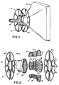
- FIG. 1 shows the deflection yoke 50 according to one embodiment of the present invention installed on the rear of a CRT 52, and including low eddy current heat sinks 54 and 56.
- the heat sinks 54 and 56 extend radially outward from the neck 58 of the CRT 52 and are spaced apart to provide an opportunity for air flow therethrough to remove the heat of the heat sinks 54 and 56.
- the yoke 50 is shown in exploded view in Fig. 2 wherein the horizontal deflection coils 60 and 62 are surrounded by the vertical deflection coils 64 and 66 when seated in slots 68 of a deflection yoke core 70.
- the heat sinks 54 and 56 comprise overlapped, staggered windings 55 and 57 which typically provide a mechanically and thermally continuous center ring 51, 53 which is retained by the deflection windings 60-66.
- the heat sinks 54 and 56 typically are retained on the outside axial end portions 65, 67 of the vertical coils 64, 66 and overlapped by the axial end portions 61 and 63 of the horizontal coils 60, 62.
- the thermal conduction between the deflection windings and the heat sinks 54 and 56 may be further enhanced by securably fastening the axial end portions of the deflection windings 60, 62 and 64, 66 more tightly about the inner portions 51, 53 of the heat sinks 54 and 56.
- the heat sinks 54 and 56 include a plurality of fine wires and typically have unconnected ends 59 so as to provide an open circuit loop.
- the deflection yoke provided by the structure according to Fig. 2 removes the heat from the deflection coils to the heat sinks 54 and 56. Moreover, the heat produced by the deflection yoke core 70 material itself is removed by the heat or thermal conduction of the deflection coils themselves, wherein heat is transferred to the thermal sink radiators 54 and 56 not being a part of the deflection winding.
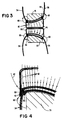
- the B-field pattern of Fig. 3 displays the leakage fields 80 and the deflection field 82 of the deflection yoke 50, shown in cross-section.
- Fig. 4 shows leakage field 80 in detail and part of deflection field 82 cutting through heat sink 54 and thereby potentially inducing eddy currents.
- the forward heat sink 56 and rear heat sink 54 are shown and retained between orthogonal axis deflection coils 84 and 86 at their axial end portions. It is appreciated that heat may be extracted by inserting a heat-conducting element in the manner shown in Fig. 3.
- the outward-extending magnetic fields 80 and 82 typically comprising a high frequency, alternating field, would induce significant eddy currents in solid heat sinks if substituted for the low eddy current heat sinks 54 and 56 of the present invention.
Landscapes
- Details Of Television Scanning (AREA)
Description
- The present invention relates to deflection yokes and, in particular, to deflection yokes including heat dissipation elements.
- High-performance raster scan CRT displays require high resolution rasters. In order to provide a high resolution raster display, the beam must be deflected rapidly across the screen of the CRT. As the speed requirement increases, the resistive losses of the deflection coils increase because of "skin effect". This increase in loss can be minimized, but not eliminated, by the use of Litzendraht (litz) wire in these coils. Moreover, as the frequencies increase, the deflection yoke core, typically a powdered ferrite material, itself begins to heat up due to the material loss at high energy and high frequency.
- Previous attempts to improve deflection yoke performance in CRT displays have included elements to sense the temperature of the deflection yoke and compensate or adjust the deflection circuit in response thereto. However, since this does not reduce the temperature of the deflection yoke, this technique provides no improvement on the ultimate power which may be provided to the deflection yoke.
- Other more drastic techniques evade the problem by scanning with as many as eight separate controlled electron beam paths, reducing the number of scan lines and therefore scan deflection rate. However, this technique incurs an extreme economic penalty and redundant CRT electron gun driving and data separation circuitry.
- An example of a yoke assembly provided with a heat sink formed as an element not being a part of the deflection winding can be found in JP-A-58 220 343.
- A basic design for a core retaining a deflection winding is disclosed in JP-A-6 1-66 347.
- The concept of using Litz wire in a deflection coil to reduce eddy current losses in known from US-A-4 484 166.
- Therefore, the present state of the art provides techniques for reducing the temperature of the deflection yoke, and further appreciates the problems underlying the heat buildup in the deflection yoke.
- A high performance deflection yoke according to the present invention as claimed in claim 1 includes a deflection winding as defined in claim 1. Preferably, the heat sink comprises a low loss, low eddy current wire heat sink element interposed between the axial end portions of the horizontal and vertical deflection coils, extending radially outward from the deflection yoke. The heat sink comprises multiple conductor wire elements of a good heat conducting material, such as copper litz wire, comprising a plurality of smaller wires, each insulated one from another to inhibit the production of eddy currents in the heat sink itself. Moreover, the deflection yoke core itself is also cooled. As the deflection coils are cooled, the deflection coils, typically copper, transfer the heat from the deflection yoke core material to the heat sink. As a result, the deflection yoke according to the present invention provides extended high-performance operation not previously realizable in the art, thus permitting the realization of high-performance CRT displays not previously available.
- These and other features according to the present invention will be better understood by reading the following detailed description of the drawing, taken together with the drawing wherein :
- Fig. 1 is a rear perspective view of the deflection yoke according to one embodiment of the present invention as mounted on the typical CRT ;
- Fig. 2 is an exploded view of a deflection yoke according to the embodiment of Fig. 1 ;
- Fig. 3 is a cross-sectional diagram of the deflection yoke of Fig. 2 showing deflection and leakage fields external to the deflection yoke; and
- Fig. 4 shows an expansion of the field shown in Fig. 3.
- The perspective view of Fig. 1 shows the
deflection yoke 50 according to one embodiment of the present invention installed on the rear of aCRT 52, and including low eddycurrent heat sinks neck 58 of the CRT 52 and are spaced apart to provide an opportunity for air flow therethrough to remove the heat of theheat sinks yoke 50 is shown in exploded view in Fig. 2 wherein thehorizontal deflection coils vertical deflection coils deflection yoke core 70. The heat sinks 54 and 56 comprise overlapped, staggeredwindings continuous center ring heat sinks axial end portions vertical coils axial end portions horizontal coils heat sinks deflection windings inner portions heat sinks unconnected ends 59 so as to provide an open circuit loop. - The deflection yoke provided by the structure according to Fig. 2 removes the heat from the deflection coils to the
heat sinks yoke core 70 material itself is removed by the heat or thermal conduction of the deflection coils themselves, wherein heat is transferred to thethermal sink radiators - To further appreciate the present invention, the B-field pattern of Fig. 3 displays the
leakage fields 80 and thedeflection field 82 of thedeflection yoke 50, shown in cross-section. Fig. 4 showsleakage field 80 in detail and part ofdeflection field 82 cutting throughheat sink 54 and thereby potentially inducing eddy currents. Theforward heat sink 56 andrear heat sink 54 are shown and retained between orthogonalaxis deflection coils magnetic fields current heat sinks - Furthermore, it is also appreciated that other embodiments of the present invention are envisioned which are thermally coupled in other ways to the
deflection yoke 50 and thedeflection coils heat sinks
Claims (7)
- A high performance deflection yoke comprising a deflection winding (60, 62, 64, 66) and a heat sink means (54, 56) not being a part of said deflection winding,
characterized in that said heat sink means comprises low eddy current wire elements (54, 56), said wire elements comprising a plurality of electrically conductive wires which wires are electrically insulated from one another, said heat sink means being in thermal contact with said deflection winding and extending radially outward from said deflection winding, for transferring heat generated by said deflection winding away from said deflection winding. - A high-performance deflection yoke according to claim 1, further comprising a core (70) retaining said deflection winding (60, 62, 64, 66).
- A high-performance deflection yoke according to claim 2, wherein said low eddy current wire elements (54, 56) comprise litz wire.
- A high-performance deflection yoke according to any one of claims 1 to 3, wherein said wire elements have unconnected ends (59) so as to provide an open circuit loop.
- A high-performance deflection yoke according to any one of claims 1 to 4, wherein said low eddy current wire elements (54, 56) comprise wire elements interwoven within said deflection winding.
- A high-performance deflection yoke according to any one of claims 1 to 5, wherein said low eddy current wire elements (54, 56) are juxtaposed to at least a portion of said deflection winding (60, 62, 64, 66).
- A high-performance deflection yoke according to any one of claims 1 to 6, comprising plurality of deflection windings (60, 62, 64, 66), wherein said low eddy current wire elements (54, 56) are interposed between at least a portion of the plurality of deflection windings.
Applications Claiming Priority (2)
| Application Number | Priority Date | Filing Date | Title |
|---|---|---|---|
| US895207 | 1986-08-11 | ||
| US06/895,207 US4737752A (en) | 1986-08-11 | 1986-08-11 | Oscilloscope deflection yoke with heat dissipation means |
Publications (3)
| Publication Number | Publication Date |
|---|---|
| EP0256943A2 EP0256943A2 (en) | 1988-02-24 |
| EP0256943A3 EP0256943A3 (en) | 1989-04-05 |
| EP0256943B1 true EP0256943B1 (en) | 1994-01-26 |
Family
ID=25404153
Family Applications (1)
| Application Number | Title | Priority Date | Filing Date |
|---|---|---|---|
| EP87401852A Expired - Lifetime EP0256943B1 (en) | 1986-08-11 | 1987-08-07 | Oscilloscope deflection yoke with heat dissipation means |
Country Status (4)
| Country | Link |
|---|---|
| US (1) | US4737752A (en) |
| EP (1) | EP0256943B1 (en) |
| JP (1) | JPH0677440B2 (en) |
| DE (1) | DE3788907T2 (en) |
Families Citing this family (11)
| Publication number | Priority date | Publication date | Assignee | Title |
|---|---|---|---|---|
| US5204649A (en) * | 1989-11-09 | 1993-04-20 | Mitsubishi Denki Kabushiki Kaisha | Deflection yoke |
| KR930000791B1 (en) * | 1989-11-09 | 1993-02-04 | 미쯔비시덴끼 가부시끼가이샤 | Deflection yoke |
| US5012104A (en) * | 1990-05-17 | 1991-04-30 | Etec Systems, Inc. | Thermally stable magnetic deflection assembly and method of making same |
| JPH0782818B2 (en) * | 1990-09-14 | 1995-09-06 | 防衛庁技術研究本部長 | Heat sink for deflection coil |
| KR100193580B1 (en) * | 1995-11-30 | 1999-06-15 | 이형도 | Mermaid Arm of Deflection York |
| KR20010024169A (en) * | 1998-07-21 | 2001-03-26 | 요트.게.아. 롤페즈 | Cathode ray tube having a deflection unit provided with a fan |
| EP1046181A1 (en) * | 1998-09-11 | 2000-10-25 | Koninklijke Philips Electronics N.V. | Cathode ray tube comprising a yoke ring provided with a cooling fin |
| JP2002042686A (en) | 2000-07-24 | 2002-02-08 | Matsushita Electric Ind Co Ltd | Color picture tube equipment |
| WO2012135939A1 (en) * | 2011-04-05 | 2012-10-11 | Comaintel Inc. | Induction heating workcoil |
| GB201409177D0 (en) * | 2014-05-23 | 2014-07-09 | Qinetiq Ltd | Improvements to the cooling of electric motors |
| US20240326651A1 (en) * | 2023-03-30 | 2024-10-03 | InductEV, Inc. | System and method for thermal management of an inductive wireless power charger |
Family Cites Families (7)
| Publication number | Priority date | Publication date | Assignee | Title |
|---|---|---|---|---|
| CA716216A (en) * | 1965-08-17 | Dominion Electrohome Industries Limited | Temperature compensated toroidal electromagnetic deflection yokes | |
| FR1598193A (en) * | 1967-11-21 | 1970-07-06 | ||
| JPS4822364B1 (en) * | 1968-10-09 | 1973-07-05 | ||
| JPS5823106A (en) * | 1981-07-31 | 1983-02-10 | 株式会社日立製作所 | Winding wire and coil using the same |
| JPS58220343A (en) * | 1982-06-15 | 1983-12-21 | Matsushita Electric Ind Co Ltd | Cathode-ray tube apparatus |
| NL8203133A (en) * | 1982-08-09 | 1984-03-01 | Philips Nv | DEFLECTION Yoke. |
| JPH0652649B2 (en) * | 1984-02-22 | 1994-07-06 | 株式会社日立製作所 | Deflection yoke |
-
1986
- 1986-08-11 US US06/895,207 patent/US4737752A/en not_active Expired - Fee Related
-
1987
- 1987-08-07 EP EP87401852A patent/EP0256943B1/en not_active Expired - Lifetime
- 1987-08-07 DE DE3788907T patent/DE3788907T2/en not_active Expired - Fee Related
- 1987-08-11 JP JP62200744A patent/JPH0677440B2/en not_active Expired - Lifetime
Also Published As
| Publication number | Publication date |
|---|---|
| EP0256943A2 (en) | 1988-02-24 |
| JPS6362138A (en) | 1988-03-18 |
| DE3788907T2 (en) | 1994-07-14 |
| US4737752A (en) | 1988-04-12 |
| EP0256943A3 (en) | 1989-04-05 |
| JPH0677440B2 (en) | 1994-09-28 |
| DE3788907D1 (en) | 1994-03-10 |
Similar Documents
| Publication | Publication Date | Title |
|---|---|---|
| US4737752A (en) | Oscilloscope deflection yoke with heat dissipation means | |
| US20230215613A1 (en) | Thermal management of electromagnetic device | |
| EP0716433B1 (en) | High Q integrated inductor | |
| EP0258891B2 (en) | Deflection yoke apparatus with means for reducing unwanted radiation | |
| KR930000791B1 (en) | Deflection yoke | |
| CA1186944A (en) | Electromagnetic print hammer coil assembly | |
| AU746801B2 (en) | Flux guiding and cooling arrangements for induction heating units | |
| US11443882B2 (en) | Coil device | |
| EP3921855B1 (en) | Inductors with core structure supporting multiple air flow modes | |
| JPH1074634A (en) | Converter transformer | |
| JPH0652649B2 (en) | Deflection yoke | |
| US5111174A (en) | Shielded high frequency power transformer | |
| US3274418A (en) | Field concentrator having conductive loop proximate beam | |
| GB2273199A (en) | Electron beam collector | |
| US20260051777A1 (en) | Flexible circuit board and rotating electric machine | |
| JP3642109B2 (en) | Deflection yoke | |
| JP3636484B2 (en) | Electromagnetic cooker | |
| JPS6132335A (en) | Deflection yoke | |
| US20020008459A1 (en) | Cathode ray tube | |
| JP3217531B2 (en) | Superconducting rotor | |
| JPS62194602A (en) | Cooling structure of winding in stationary induction apparatus | |
| JPS6355882A (en) | Heating coil for induction cooker | |
| JPS61196504A (en) | magnetic field generator | |
| JPH01200542A (en) | Deflecting device | |
| JPH06150848A (en) | Deflection yoke |
Legal Events
| Date | Code | Title | Description |
|---|---|---|---|
| PUAI | Public reference made under article 153(3) epc to a published international application that has entered the european phase |
Free format text: ORIGINAL CODE: 0009012 |
|
| AK | Designated contracting states |
Kind code of ref document: A2 Designated state(s): DE FR GB |
|
| PUAL | Search report despatched |
Free format text: ORIGINAL CODE: 0009013 |
|
| AK | Designated contracting states |
Kind code of ref document: A3 Designated state(s): DE FR GB |
|
| 17P | Request for examination filed |
Effective date: 19890919 |
|
| 17Q | First examination report despatched |
Effective date: 19910806 |
|
| RAP1 | Party data changed (applicant data changed or rights of an application transferred) |
Owner name: E-SYSTEMS INC. |
|
| GRAA | (expected) grant |
Free format text: ORIGINAL CODE: 0009210 |
|
| AK | Designated contracting states |
Kind code of ref document: B1 Designated state(s): DE FR GB |
|
| REF | Corresponds to: |
Ref document number: 3788907 Country of ref document: DE Date of ref document: 19940310 |
|
| ET | Fr: translation filed | ||
| PLBE | No opposition filed within time limit |
Free format text: ORIGINAL CODE: 0009261 |
|
| STAA | Information on the status of an ep patent application or granted ep patent |
Free format text: STATUS: NO OPPOSITION FILED WITHIN TIME LIMIT |
|
| 26N | No opposition filed | ||
| PGFP | Annual fee paid to national office [announced via postgrant information from national office to epo] |
Ref country code: GB Payment date: 19980702 Year of fee payment: 12 |
|
| PGFP | Annual fee paid to national office [announced via postgrant information from national office to epo] |
Ref country code: FR Payment date: 19980806 Year of fee payment: 12 |
|
| PGFP | Annual fee paid to national office [announced via postgrant information from national office to epo] |
Ref country code: DE Payment date: 19980827 Year of fee payment: 12 |
|
| PG25 | Lapsed in a contracting state [announced via postgrant information from national office to epo] |
Ref country code: GB Free format text: LAPSE BECAUSE OF NON-PAYMENT OF DUE FEES Effective date: 19990807 |
|
| GBPC | Gb: european patent ceased through non-payment of renewal fee |
Effective date: 19990807 |
|
| PG25 | Lapsed in a contracting state [announced via postgrant information from national office to epo] |
Ref country code: FR Free format text: LAPSE BECAUSE OF NON-PAYMENT OF DUE FEES Effective date: 20000428 |
|
| PG25 | Lapsed in a contracting state [announced via postgrant information from national office to epo] |
Ref country code: DE Free format text: LAPSE BECAUSE OF NON-PAYMENT OF DUE FEES Effective date: 20000601 |
|
| REG | Reference to a national code |
Ref country code: FR Ref legal event code: ST |