EP0256826A2 - Wärmebilderzeuger - Google Patents
Wärmebilderzeuger Download PDFInfo
- Publication number
- EP0256826A2 EP0256826A2 EP87307066A EP87307066A EP0256826A2 EP 0256826 A2 EP0256826 A2 EP 0256826A2 EP 87307066 A EP87307066 A EP 87307066A EP 87307066 A EP87307066 A EP 87307066A EP 0256826 A2 EP0256826 A2 EP 0256826A2
- Authority
- EP
- European Patent Office
- Prior art keywords
- optical system
- energy
- thermal
- prism
- thermal imager
- Prior art date
- Legal status (The legal status is an assumption and is not a legal conclusion. Google has not performed a legal analysis and makes no representation as to the accuracy of the status listed.)
- Withdrawn
Links
- 230000003287 optical effect Effects 0.000 claims abstract description 40
- 239000000463 material Substances 0.000 claims abstract description 14
- 239000000969 carrier Substances 0.000 claims description 5
- 238000006073 displacement reaction Methods 0.000 claims description 5
- 230000000694 effects Effects 0.000 abstract description 3
- 230000005855 radiation Effects 0.000 description 7
- NCGICGYLBXGBGN-UHFFFAOYSA-N 3-morpholin-4-yl-1-oxa-3-azonia-2-azanidacyclopent-3-en-5-imine;hydrochloride Chemical compound Cl.[N-]1OC(=N)C=[N+]1N1CCOCC1 NCGICGYLBXGBGN-UHFFFAOYSA-N 0.000 description 6
- 230000004075 alteration Effects 0.000 description 5
- 238000010586 diagram Methods 0.000 description 5
- 239000002800 charge carrier Substances 0.000 description 3
- 238000009792 diffusion process Methods 0.000 description 2
- 229910000661 Mercury cadmium telluride Inorganic materials 0.000 description 1
- MCMSPRNYOJJPIZ-UHFFFAOYSA-N cadmium;mercury;tellurium Chemical compound [Cd]=[Te]=[Hg] MCMSPRNYOJJPIZ-UHFFFAOYSA-N 0.000 description 1
- 230000001419 dependent effect Effects 0.000 description 1
- 229910052732 germanium Inorganic materials 0.000 description 1
- GNPVGFCGXDBREM-UHFFFAOYSA-N germanium atom Chemical compound [Ge] GNPVGFCGXDBREM-UHFFFAOYSA-N 0.000 description 1
- 238000012986 modification Methods 0.000 description 1
- 230000004048 modification Effects 0.000 description 1
- 238000001931 thermography Methods 0.000 description 1
Images


Classifications
-
- G—PHYSICS
- G02—OPTICS
- G02B—OPTICAL ELEMENTS, SYSTEMS OR APPARATUS
- G02B13/00—Optical objectives specially designed for the purposes specified below
- G02B13/08—Anamorphotic objectives
- G02B13/10—Anamorphotic objectives involving prisms
Definitions
- This invention relates to optical systems and is particularly concerned with optical systems in thermal imagers.
- thermal imager comprises an optical scanning arrangement which causes a thermal image to be scanned in both the horizontal and vertical directions across a thermal detector so that the detector produces a video output signal which, after appropriate processing, may be used to produce a visible image on a suitable display device such as a cathode ray tube.
- the scanning optical system comprises two coaxial rotating polygonal mirrors which together perform the required scanning or a single polygonal mirror which performs a horizontal scanning and an oscillating mirror which performs the vertical scanning.
- a known form of detector comprises one or more strips of thermally responsive material extending in the horizontal line direction and electrically biassed so that charge carriers generated in the strip at one end by a given pixel move along the strip towards the other end in synchronism with the movement of the pixel and are extracted at said other end in order to form the video signal.
- Such a detector provides a good signal to noise ratio.
- the carriers generated in the strip tend to diffuse as they move along the strip in synchronism with the pixel which has generated them and as a result, carriers from one pixel may diffuse into the next thereby reducing the sharpness of the image.
- anamorphic optical elements in the optical system so as to magnify the pixels in the horizontal scanning direction and thereby reduce the diffusion of carriers from one pixel to the next.
- the problem with such anamorphic elements is that they are sensitive to temperature changes. More particularly, the material from which these elements are made may have a high rate of change of refractive index with temperature variation.
- An object of the invention is to provide an improved optical system in which compensation for variation in a parameter thereof is provided.
- Another object of the invention is to provide an anamorphic optical system, preferably for use in a thermal imager, in which variation in refractive index of an element of said system with temperature, is compensated.
- a thermal scanning arrangement 2 receives thermal energy from a field of view (not shown) and supplies the thermal energy in the form of a collimated beam 4 to an anamorphic optical system 6 comprising first and second prisms 8, 10 inverted relative to each other, a collimating lens 12, a sprite detector array 14 onto which the thermal energy is focussed by the lens 12, signal processing electronics 16 which receives a video signal from the detector array 14 and a display device 18, such as a cathode ray tube.
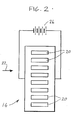
- the sprite detector 14 as shown in Figure 2, comprises an array of eight detector elements 20 each being a strip of thermally responsive material, such as cadmium-mercury-telluride.
- the scanner 2 and associated optical elements 6 to 12 cause a real thermal image to be scanned across the detector array 14.
- Each element 20 extends parallel to the horizontal scan direction of the image represented by arrow 22 in both Figure 1 and Figure 2.
- the elements 20 produce a swathe of eight video signals corresponding to eight different lines.
- the energy representing a given pixel incident on a given one of the detector elements 20 generates charge carriers therein and, as is well known, a biassing arrangement represented by 24 in Figure 2 causes the charge carriers to drift along the strip in synchronism with the movement of the pixel.
- the function of the anamorphic optical system 6 is to enlarge the thermal image on the detector in the horizontal direction and consequently enlarge each pixel in the horizontal direction. This reduces diffusion of carriers from one pixel to the next and thereby increases the sharpness of the image.
- the optical elements in thermal imaging systems are generally made of materials, such as germanium, which have a high coefficient of thermal change of refractive index. Further, optical elements made of these materials provide chromatic aberration in the thermal wavelengths.
- the prisms 6 and 8 are arranged so that chromatic aberration in the prisms and changes in refractive index due to temperature merely result in lateral displacement of the beam incident on the lens 12 so that the lateral displacement of certain wavelengths and/or the lateral displacement of the beam due to refractive index changes does not result in a change in the position of the image on the detector array.
- Figure 1 illustrates in broken lines the beam path which might arise due to chromatic aberration or changes in refractive index with temperature.
- Figure 3 shows a prism with a ray passing through.
- the incident ray is at an angle of incidentce i and the output ray is at an angle of refraction r and the angle between the faces through which the ray passes is A.
- Both prisms should be of the same material and if this condition is satisfied, the optical system will be substantially immune (within limits) both to variation in refractive index with wavelength and variation in refractive index with temperature. Otherwise, the arrangement needed to be immune to temperature variations will be different from that needed to be immune to wavelengh variations.
- Figure 6 shows a prism which has the effect of turning the radiation through 90 degrees
- Figure 7 shows an arrangement utilising two prisms similar to Figure 6 whereby the output radiation is parallel with the input radiation.
- the incident radiation a ⁇ is refracted at the input surface e ⁇ and follows path b ⁇ to be reflected internally at silvered surface f ⁇ (which may be silvered if necessary) of the prism along path c ⁇ and the output radiation is refracted at surface g ⁇ to follow path d ⁇ which is at 90 degrees to path a ⁇ .
- the path d ⁇ can be made to be at right angles to the path a ⁇ .
- Figure 7 shows an arrangement of two such prisms which have respectively silvered surfaces f ⁇ and f ⁇ whereby an output ray d ⁇ parallel to the input ray a ⁇ is produced.
- Figure 8 shows an alternative embodiment in which the output rays are parallel to the input rays.
- the input ray 30 is normal to a surface 32 (which is arranged vertically in the drawings) of a prism 34 having a first reflective surface 36 at 45 degrees to the surface 32.
- a second reflective surface d is provided to which the radiation is reflected from the surface 36 and the radiation reflected from the surface d exits through a surface c and passes to a triangular prism 38 as shown.
- the portion of the ray passing from surface d to surface c of prism 34 is labelled b and the portion of the ray passing from surface c to prism 38 is labelled a, the output beam being labelled e.
- anamorphic optical system in the illustrated embodiments comprises only two prisms, more could be included.
- the values C1, C2, M1, M2 for first and second groups of prisms could be used in calculating the required angles to satisfy Equation I.
- the invention provides a means for achieving both achromatisation and athermalisation passively and the arrangements of Figures 7 and 8 result in the input and output rays being parallel.
Landscapes
- Physics & Mathematics (AREA)
- General Physics & Mathematics (AREA)
- Optics & Photonics (AREA)
- Radiation Pyrometers (AREA)
- Lens Barrels (AREA)
- Lenses (AREA)
- Facsimile Scanning Arrangements (AREA)
- Photometry And Measurement Of Optical Pulse Characteristics (AREA)
Applications Claiming Priority (2)
| Application Number | Priority Date | Filing Date | Title |
|---|---|---|---|
| GB8619738 | 1986-08-13 | ||
| GB868619738A GB8619738D0 (en) | 1986-08-13 | 1986-08-13 | Optical systems |
Publications (2)
| Publication Number | Publication Date |
|---|---|
| EP0256826A2 true EP0256826A2 (de) | 1988-02-24 |
| EP0256826A3 EP0256826A3 (de) | 1988-08-31 |
Family
ID=10602672
Family Applications (1)
| Application Number | Title | Priority Date | Filing Date |
|---|---|---|---|
| EP87307066A Withdrawn EP0256826A3 (de) | 1986-08-13 | 1987-08-10 | Wärmebilderzeuger |
Country Status (3)
| Country | Link |
|---|---|
| US (1) | US4808823A (de) |
| EP (1) | EP0256826A3 (de) |
| GB (1) | GB8619738D0 (de) |
Cited By (6)
| Publication number | Priority date | Publication date | Assignee | Title |
|---|---|---|---|---|
| GB2222697A (en) * | 1988-09-07 | 1990-03-14 | Marconi Gec Ltd | Optical compensated optical system |
| US5136417A (en) * | 1988-09-07 | 1992-08-04 | Gec-Marconi Limited | Optical system |
| EP0499421A1 (de) * | 1991-02-15 | 1992-08-19 | Gec-Marconi (Holdings) Limited | Wärmebildsystem |
| EP0685752A1 (de) * | 1994-06-02 | 1995-12-06 | SAT (Société Anonyme de Télécommunications) | Optik für Luftüberwachungssystem |
| FR2726916A1 (fr) * | 1994-11-16 | 1996-05-15 | Thomson Csf | Oculaire anamorphoseur et dispositif d'imagerie infrarouge equipe d'un tel oculaire |
| CN106405971A (zh) * | 2016-10-28 | 2017-02-15 | 天津医科大学 | 一维温度场调制方法 |
Families Citing this family (6)
| Publication number | Priority date | Publication date | Assignee | Title |
|---|---|---|---|---|
| US5331622A (en) * | 1991-05-28 | 1994-07-19 | Applied Magnetics Corporation | Compact optical head |
| US5646778A (en) * | 1991-05-28 | 1997-07-08 | Discovision Associates | Optical beamsplitter |
| US5155633A (en) * | 1991-07-30 | 1992-10-13 | Applied Magnetics Corporation | Anamorphic achromatic prism for optical disk heads |
| FR2727215B1 (fr) * | 1994-11-18 | 1996-12-20 | Thomson Csf | Dispositif de veille panoramique infrarouge statique a detecteurs matriciels multiples |
| IL132399A (en) * | 1999-10-14 | 2004-05-12 | Elop Electrooptics Ind Ltd | Limits a numeric key |
| CN106291920B (zh) * | 2016-10-28 | 2018-12-07 | 天津医科大学 | 二维固态光扫描器 |
Citations (6)
| Publication number | Priority date | Publication date | Assignee | Title |
|---|---|---|---|---|
| US1898787A (en) * | 1932-02-25 | 1933-02-21 | Newcomer Harry Sidney | Prism anamorphoser |
| US2088660A (en) * | 1933-10-23 | 1937-08-03 | Newcomer Harry Sidney | Anamorphosing optical system |
| US2816480A (en) * | 1953-11-23 | 1957-12-17 | Superscope Inc | Prism type anamorphoscopic device |
| US4084881A (en) * | 1975-10-21 | 1978-04-18 | Canon Kabushiki Kaisha | Light beam scanning device |
| EP0005972A1 (de) * | 1978-05-26 | 1979-12-12 | The Marconi Company Limited | Infraroteinrichtungen zur Zielentdeckung |
| US4627690A (en) * | 1985-03-08 | 1986-12-09 | Polaroid Corporation | Optical system with anamorphic prism |
Family Cites Families (1)
| Publication number | Priority date | Publication date | Assignee | Title |
|---|---|---|---|---|
| GB8417993D0 (en) * | 1984-07-14 | 1984-08-15 | Pilkington Perkin Elmer Ltd | Infra-red lenses |
-
1986
- 1986-08-13 GB GB868619738A patent/GB8619738D0/en active Pending
-
1987
- 1987-08-10 EP EP87307066A patent/EP0256826A3/de not_active Withdrawn
- 1987-08-11 US US07/084,045 patent/US4808823A/en not_active Expired - Fee Related
Patent Citations (6)
| Publication number | Priority date | Publication date | Assignee | Title |
|---|---|---|---|---|
| US1898787A (en) * | 1932-02-25 | 1933-02-21 | Newcomer Harry Sidney | Prism anamorphoser |
| US2088660A (en) * | 1933-10-23 | 1937-08-03 | Newcomer Harry Sidney | Anamorphosing optical system |
| US2816480A (en) * | 1953-11-23 | 1957-12-17 | Superscope Inc | Prism type anamorphoscopic device |
| US4084881A (en) * | 1975-10-21 | 1978-04-18 | Canon Kabushiki Kaisha | Light beam scanning device |
| EP0005972A1 (de) * | 1978-05-26 | 1979-12-12 | The Marconi Company Limited | Infraroteinrichtungen zur Zielentdeckung |
| US4627690A (en) * | 1985-03-08 | 1986-12-09 | Polaroid Corporation | Optical system with anamorphic prism |
Cited By (12)
| Publication number | Priority date | Publication date | Assignee | Title |
|---|---|---|---|---|
| GB2222697A (en) * | 1988-09-07 | 1990-03-14 | Marconi Gec Ltd | Optical compensated optical system |
| US5136417A (en) * | 1988-09-07 | 1992-08-04 | Gec-Marconi Limited | Optical system |
| EP0499421A1 (de) * | 1991-02-15 | 1992-08-19 | Gec-Marconi (Holdings) Limited | Wärmebildsystem |
| GB2253716A (en) * | 1991-02-15 | 1992-09-16 | Marconi Gec Ltd | Thermal imager scanning system having optical anamorphic system |
| US5274489A (en) * | 1991-02-15 | 1993-12-28 | Gec-Marconi Limited | Thermal imager systems |
| GB2253716B (en) * | 1991-02-15 | 1994-02-09 | Marconi Gec Ltd | Thermal imager system having anamorphic optical system |
| EP0685752A1 (de) * | 1994-06-02 | 1995-12-06 | SAT (Société Anonyme de Télécommunications) | Optik für Luftüberwachungssystem |
| FR2720841A1 (fr) * | 1994-06-02 | 1995-12-08 | Sat | Optique pour système de veille aérienne. |
| FR2726916A1 (fr) * | 1994-11-16 | 1996-05-15 | Thomson Csf | Oculaire anamorphoseur et dispositif d'imagerie infrarouge equipe d'un tel oculaire |
| EP0713116A1 (de) * | 1994-11-16 | 1996-05-22 | Thomson-Csf | Anamorphotisches System und Wärmebildgerät mit einem derartigen System |
| CN106405971A (zh) * | 2016-10-28 | 2017-02-15 | 天津医科大学 | 一维温度场调制方法 |
| CN106405971B (zh) * | 2016-10-28 | 2019-05-07 | 天津医科大学 | 一维温度场调制方法 |
Also Published As
| Publication number | Publication date |
|---|---|
| US4808823A (en) | 1989-02-28 |
| GB8619738D0 (en) | 1986-09-24 |
| EP0256826A3 (de) | 1988-08-31 |
Similar Documents
| Publication | Publication Date | Title |
|---|---|---|
| US4272684A (en) | Optical beam-splitting arrangements on object side of a lens | |
| EP0499421B1 (de) | Wärmebildsystem | |
| US4930896A (en) | Surface structure measuring apparatus | |
| US4872747A (en) | Use of prisms to obtain anamorphic magnification | |
| EP0300571B1 (de) | Optisches Rastermikroskop | |
| EP0256826A2 (de) | Wärmebilderzeuger | |
| EP0067477A2 (de) | Radiometrische Einrichtung zur Messung der Temperatur | |
| EP0071531B1 (de) | Abtastvorrichtung für Vorwärts-Infrarotsysteme | |
| GB2250155A (en) | An imager with image microscanned over sensor array | |
| US5867318A (en) | Wide-angle optical system | |
| US4202597A (en) | Optical scanning system with compensation for unwanted image rotation during scanning | |
| US20140353512A1 (en) | Scanning optical system, optical scanning apparatus, and radiation image readout apparatus | |
| US4329050A (en) | Strip-field spectroradiometer | |
| GB2187301A (en) | Thermally compensated anamorphotic optical system | |
| US4848863A (en) | Multi-wavelength scanning system | |
| RU2528109C1 (ru) | Система импульсной лазерной локации | |
| US4516159A (en) | Elevation step scanner | |
| US4762989A (en) | Image detection with image plane divider | |
| Cooper et al. | Optical design of a diode laser based dynamic IR scene projector | |
| US5136417A (en) | Optical system | |
| GB2047424A (en) | Infra red imager having rotatable prism | |
| GB2182457A (en) | Compensated optical mounting | |
| EP0423409A1 (de) | Optisches System | |
| CA1303217C (en) | Apparatus including multielement detectors for recording heat images | |
| JPS59127017A (ja) | 光学走査装置 |
Legal Events
| Date | Code | Title | Description |
|---|---|---|---|
| PUAI | Public reference made under article 153(3) epc to a published international application that has entered the european phase |
Free format text: ORIGINAL CODE: 0009012 |
|
| AK | Designated contracting states |
Kind code of ref document: A2 Designated state(s): BE DE FR GB IT NL SE |
|
| PUAL | Search report despatched |
Free format text: ORIGINAL CODE: 0009013 |
|
| RHK1 | Main classification (correction) |
Ipc: G02B 13/10 |
|
| AK | Designated contracting states |
Kind code of ref document: A3 Designated state(s): BE DE FR GB IT NL SE |
|
| 17P | Request for examination filed |
Effective date: 19890220 |
|
| 17Q | First examination report despatched |
Effective date: 19910628 |
|
| STAA | Information on the status of an ep patent application or granted ep patent |
Free format text: STATUS: THE APPLICATION IS DEEMED TO BE WITHDRAWN |
|
| 18D | Application deemed to be withdrawn |
Effective date: 19920109 |
|
| RIN1 | Information on inventor provided before grant (corrected) |
Inventor name: STUART, ALAN STANLEY Inventor name: MOORE, WILLIAM THOMAS |