EP0256722A2 - Scheidewandsystem mit Haken und Ösen - Google Patents
Scheidewandsystem mit Haken und Ösen Download PDFInfo
- Publication number
- EP0256722A2 EP0256722A2 EP87306774A EP87306774A EP0256722A2 EP 0256722 A2 EP0256722 A2 EP 0256722A2 EP 87306774 A EP87306774 A EP 87306774A EP 87306774 A EP87306774 A EP 87306774A EP 0256722 A2 EP0256722 A2 EP 0256722A2
- Authority
- EP
- European Patent Office
- Prior art keywords
- shaped member
- portions
- partitioning
- fastening
- shaped members
- Prior art date
- Legal status (The legal status is an assumption and is not a legal conclusion. Google has not performed a legal analysis and makes no representation as to the accuracy of the status listed.)
- Withdrawn
Links
Images
Classifications
-
- F—MECHANICAL ENGINEERING; LIGHTING; HEATING; WEAPONS; BLASTING
- F16—ENGINEERING ELEMENTS AND UNITS; GENERAL MEASURES FOR PRODUCING AND MAINTAINING EFFECTIVE FUNCTIONING OF MACHINES OR INSTALLATIONS; THERMAL INSULATION IN GENERAL
- F16B—DEVICES FOR FASTENING OR SECURING CONSTRUCTIONAL ELEMENTS OR MACHINE PARTS TOGETHER, e.g. NAILS, BOLTS, CIRCLIPS, CLAMPS, CLIPS OR WEDGES; JOINTS OR JOINTING
- F16B12/00—Jointing of furniture or the like, e.g. hidden from exterior
- F16B12/44—Leg joints; Corner joints
- F16B12/46—Non-metal corner connections
-
- E—FIXED CONSTRUCTIONS
- E04—BUILDING
- E04B—GENERAL BUILDING CONSTRUCTIONS; WALLS, e.g. PARTITIONS; ROOFS; FLOORS; CEILINGS; INSULATION OR OTHER PROTECTION OF BUILDINGS
- E04B2/00—Walls, e.g. partitions, for buildings; Wall construction with regard to insulation; Connections specially adapted to walls
- E04B2/74—Removable non-load-bearing partitions; Partitions with a free upper edge
- E04B2/7407—Removable non-load-bearing partitions; Partitions with a free upper edge assembled using frames with infill panels or coverings only; made-up of panels and a support structure incorporating posts
-
- A—HUMAN NECESSITIES
- A47—FURNITURE; DOMESTIC ARTICLES OR APPLIANCES; COFFEE MILLS; SPICE MILLS; SUCTION CLEANERS IN GENERAL
- A47B—TABLES; DESKS; OFFICE FURNITURE; CABINETS; DRAWERS; GENERAL DETAILS OF FURNITURE
- A47B2230/00—Furniture jointing; Furniture with such jointing
- A47B2230/0003—Adjustable furniture jointing
- A47B2230/0011—Hooks and loops as in hook and look-type fastener
-
- F—MECHANICAL ENGINEERING; LIGHTING; HEATING; WEAPONS; BLASTING
- F16—ENGINEERING ELEMENTS AND UNITS; GENERAL MEASURES FOR PRODUCING AND MAINTAINING EFFECTIVE FUNCTIONING OF MACHINES OR INSTALLATIONS; THERMAL INSULATION IN GENERAL
- F16B—DEVICES FOR FASTENING OR SECURING CONSTRUCTIONAL ELEMENTS OR MACHINE PARTS TOGETHER, e.g. NAILS, BOLTS, CIRCLIPS, CLAMPS, CLIPS OR WEDGES; JOINTS OR JOINTING
- F16B2200/00—Constructional details of connections not covered for in other groups of this subclass
- F16B2200/81—Use of a material of the hooks-and-loops type
Definitions
- the present invention relates to partitioning systems for offices and the like wherein preformed planar wall partitions are releasably attached to one another and other partitioning components and, more particularly to an improved fastening system of the touch fastener (e.g. hook and loop type) for releasably fastening partitioning components together in shear characterized by a first U-shaped member adapted to fit over and attach to an edge of a wall partition to be joined to another partitioning component and having parallel outer faces each having one of the portions of the fastening system thereon; and, a second U-shaped member adapted to be carried by the other partitioning component and having parallel inner faces on the sides of the U each having the other of the portions of the fastening system thereon, the second U-shaped member being adapted to receive the first U-shaped member and its wall partition between the inner faces with the portions of the loop fastening portions in engagement; and being further adapted to have the sides pivoted adjacent the closed end of the U to allow progressive disengagement of the portions of the fastening system.
- Repositionable wall systems are quite popular in modern offices. Often referred to as "modular" systems, they allow an enlarged area containing no inner supporting walls to be dynamically divided into office spaces, and the like on an as-needed basis. That is, spaces can be defined for any term of time that meets the requirements of the business using them and can then be disassembled and reconfigured to meet new need.
- the wall panels that comprise the basic component or "building blocks” of these systems can be made to be of light weight and of good sound deadening characteristics.
- the problem area is that of fastening the panels to one another and to the other components of the system such as outside walls and furniture, such as desks, being used for support and anchor points.
- outside walls and furniture such as desks
- cam locking mechanisms within the framework. Pins can be inserted into matching adjoining locking mechanisms in adjacent panels and the locking mechanisms cam locked to the pins to lock the panels together. While such prior art fastening systems work, they are complex, expensive, and impractical for attaching to the desks and outside walls. Where it is desired to employ lightweight, unitary panels having no outside framework to house the locking mechanisms, such fastening systems become completely impossible to employ.
- a partitioning system for offices and the like wherein preformed planar wall partitions are releasably attached to one another and other partitioning components by touch fasteners characterized by:
- the second U-shaped member comprises a pair of U-shaped members each adapted to receive a first U-shaped member therein and each includes the parallel inner faces each having the other of the portions of the fastening system thereon whereby two wall panels having the first U-shaped members on facing edges thereof can be joined thereby.
- the two U-shaped members are disposed back to back.
- the two U-shaped members are disposed at right angles for joining two wall panels at a corner.
- the second U-shaped member is a resiliently rigid channel having a back portion and two parallel facing side portions wherein the side portions are hingedly attached to the back portion.
- the second U-shaped member has adhesive on the outer surface of the back portion for adhesvely attaching the second U-shaped member to a surface.
- the adhesive is provided on the outside of one of the side portions whereby the second U-shaped member can be hingedly unfolded flat against the surface to receive the first U-shaped member therein.
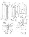
- the trap channel is indicated as 10 and comprises a back portion 12 from which two parallel, spaced side portions 14 extend.
- the trap channels 10 are made of resiliently rigid plastic and the hinges 18 described with relation thereto are so-called "living hinges" formed into the plastic material.
- both side portions 14 are hingedly attached to the back portion 12 such that both can swing outward, as indicated by the dotted ghost lines, for release of the touch fastener employed therewith. Attachment of something to be fastened therewith is made to the back portion.
- only one side portion 14 is hingedly attached to the back, as indicated by the single dotted ghost line.
- Attachment to this embodiment is made to either the back portion 12 or the other side portion l4.
- the facing inner surfaces of the side portions 14 have the hook portion 16 of hook and loop type fastening material thereon.
- the basic shear trap channel 10 of this invention is of tough, resilient plastic and comprises a back portion 12 from which parallel, spaced side portions 14 extend. At the points where the side portions 14 join the back portion 12, there are longitudinal living hinges 18. While the fastening material could be employed on only the side portions 14, in this particular invention it is preferred that the fastening material be used on the inner surfaces of the side and back portions 14, 12. As described in the above-referenced co-pending application, either the hook or loop portion can be used in the trap channel; but it is preferred to use the hook material 16 therein as indicated in Figure 3.
- FIG. 6 The use and operation of the shear trap channel fastening system with relation to wall panels, and the like, is depicted in Figure 6.
- a U-shaped piece of the loop portion of the hook and loop fastening material such as that sold by the assignee of the present invention under the trademark Velcro, generally indicated as 20, is disposed over the edge 22 of the panel 24.
- the U-shaped piece of loop material 20 can, and in most cases will, comprise an adhesive-backed strip of the loop material which is fit around the edge 22 into the U-shape as shown.
- a pre-formed U-shaped member could, of course, be employed and attached adhesively or otherwise, to the edge 22 is desired.
- the edge 22 is pressed into the hook portion 16 on the back portion 12 and then the side portions 14 are swung about the living hinges 18 to engage the hook and loop portions 16, 20 thereon. To release the panel 24 from the trap channel 10, the process is simply reversed.
- FIGs 4, 5, 7 and 8 Several configurations for the trap channels, singly or in combination, are shown in Figures 4, 5, 7 and 8.
- a trap channel fastener 26 is shown for fastening two planar wall panels, or the like together in a common plane such as in the construction of a common wall.
- the fastener 26 comprises two shear trap channels 10 of the type shown in Figure 3 in back to back relationship. This could be accomplished by a common extrusion or by adhesively fastening two channels 10 together such as with adhesive strip.
- a second fastener 28 is shown in Figure 5 which is of a type which would be used for fastening two planar panels together at an angle to one another.
- the two trap channels 10 are joined together at their respective corners 30 by a thin strip 32 acting as a living hinge to provide adjustability of the angle.
- a longtudinal triangular strip 34 can be fastened to the back portions 12 as by adhesive strips (not shown) for decorative purposes and to hold a firm pre-established angle (such as 90°) as shown.
- the living hinge 32 could be omitted and the two trap channels 10 and the triangular strip 34 extruded in a unitary construction.
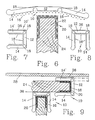
- FIG. 7 and 8 are employed for fastening a planar panel to a surface such as an outside wall or a desk.
- the trap channel 10 ⁇ of Figure 7 is used for parallel attachment while the trap channel 10 of Figure 8 is used for perpendicular attachment.
- This is shown in Figure 9.
- a strip 36 of peel and stick adhesive (many of which are well known in the art) is used for fastening to the surface.
- the trap channel 10 ⁇ of Figure 7 has a planar side portion 14 ⁇ adapted to fit flat against the side of the desk 38. As previously described, the trap channel 10 ⁇ because of the two living hinges 18, can be swung outward flat against the desk side 38 as indicated by the dotted lines.
- modular wall and partitioning systems can be constructed which are simple, lightweight, secure, and easy to use and reconfigure.
- cross-section of the channel of Figures 1 and 2 may be varied without departing from the inventive concept, for example, the sides might converge to engage a triangular member or might be curved to engage a circular or otherwise curved member.
- channel members would be part of the panels 24 to engage supports carrying portions corresponding to edges 22.
- a touch fastener as used in this application, comprises a first planar backing material part having a surface carrying hooks, mushrooms, balls on stems, pigtails, or the like, capable of engaging loops, hooks, mushrooms, balls on stems, pigtails, or the like, carried by a second planar backing material part to releasably fasten components together wherein the fastening strength in shear (i.e. against forces applied in the plane of the fastener) substantially exceeds the fastening strength resisting peeling separation of the fastener by the application of force normal to the plane thereof.
- hook and loop fastening systems and parts thereof shall be construed to include other types of touch fasteners in which the fastening strength in shear (i.e. against forces applied in the plane of the fastener) substantially exceeds the fastening strength resisting peeling separation of the fastener by the application of force normal to the plane thereof.
Landscapes
- Engineering & Computer Science (AREA)
- General Engineering & Computer Science (AREA)
- Architecture (AREA)
- Mechanical Engineering (AREA)
- Physics & Mathematics (AREA)
- Electromagnetism (AREA)
- Civil Engineering (AREA)
- Structural Engineering (AREA)
- Clamps And Clips (AREA)
- Moulds, Cores, Or Mandrels (AREA)
- Connection Of Plates (AREA)
Applications Claiming Priority (2)
| Application Number | Priority Date | Filing Date | Title |
|---|---|---|---|
| US89338286A | 1986-08-05 | 1986-08-05 | |
| US893382 | 1986-08-05 |
Publications (2)
| Publication Number | Publication Date |
|---|---|
| EP0256722A2 true EP0256722A2 (de) | 1988-02-24 |
| EP0256722A3 EP0256722A3 (de) | 1989-08-23 |
Family
ID=25401469
Family Applications (1)
| Application Number | Title | Priority Date | Filing Date |
|---|---|---|---|
| EP87306774A Withdrawn EP0256722A3 (de) | 1986-08-05 | 1987-07-30 | Scheidewandsystem mit Haken und Ösen |
Country Status (1)
| Country | Link |
|---|---|
| EP (1) | EP0256722A3 (de) |
Cited By (3)
| Publication number | Priority date | Publication date | Assignee | Title |
|---|---|---|---|---|
| DE8908045U1 (de) * | 1989-07-01 | 1990-10-31 | Zöschinger, Klaus, 8872 Burgau | Wand |
| US5096805A (en) * | 1988-07-25 | 1992-03-17 | Fuji Photo Film Co., Ltd. | Silver halide color photographic material containing 5-pyrazolone magenta coupler and amine-type stain preventing agent |
| WO2002099212A1 (de) * | 2001-05-25 | 2002-12-12 | Gerhard Fauner | Geklettete hochbaukonstruktion |
Family Cites Families (3)
| Publication number | Priority date | Publication date | Assignee | Title |
|---|---|---|---|---|
| GB1351137A (en) * | 1970-03-18 | 1974-04-24 | Supalite Displays Ltd | Free-standing building structures |
| US4271566A (en) * | 1976-12-13 | 1981-06-09 | Velcro Usa Inc. | Shear attachments using hook and loop fastener elements |
| DE3500064A1 (de) * | 1985-01-03 | 1986-07-03 | Bernhard 7101 Untereisesheim Meier | Profilleiste, insbesondere fuer verkaufsmoebel |
-
1987
- 1987-07-30 EP EP87306774A patent/EP0256722A3/de not_active Withdrawn
Cited By (3)
| Publication number | Priority date | Publication date | Assignee | Title |
|---|---|---|---|---|
| US5096805A (en) * | 1988-07-25 | 1992-03-17 | Fuji Photo Film Co., Ltd. | Silver halide color photographic material containing 5-pyrazolone magenta coupler and amine-type stain preventing agent |
| DE8908045U1 (de) * | 1989-07-01 | 1990-10-31 | Zöschinger, Klaus, 8872 Burgau | Wand |
| WO2002099212A1 (de) * | 2001-05-25 | 2002-12-12 | Gerhard Fauner | Geklettete hochbaukonstruktion |
Also Published As
| Publication number | Publication date |
|---|---|
| EP0256722A3 (de) | 1989-08-23 |
Similar Documents
| Publication | Publication Date | Title |
|---|---|---|
| US4879854A (en) | Hook and loop partitioning system | |
| US5826639A (en) | Reversible arcuate panel device | |
| CA1112406A (en) | Hinge structure | |
| US5373678A (en) | Structural panel system | |
| US4887338A (en) | Shear trap hook and loop fastening system | |
| US5678383A (en) | Construction assembly for supporting thin panels | |
| US5737893A (en) | Panel construction and connection system | |
| US5240342A (en) | Variable angle joist support | |
| US4716699A (en) | Wall panels with single load-bearing connector posts | |
| US4067165A (en) | Panel system | |
| US2962133A (en) | Construction unit having marginal interconnecting means | |
| US6349904B1 (en) | Cable bundling and support device | |
| US9194121B2 (en) | Tangential non-dimensional interface module | |
| GB2033044A (en) | Device for joining panels together | |
| US3777435A (en) | Attachment assembly | |
| US5328139A (en) | Wall article hanging device | |
| WO1989002035A1 (en) | Fastening device for support structures | |
| JP3205757B2 (ja) | 仕事空間管理システム | |
| GB2335944A (en) | Non-racking panel display device | |
| IL44012A (en) | Panel-shaped furnishing components hinged by fastener tapes | |
| US10420320B1 (en) | Device for securing a portion of a sheet of flexible material and an item of pet furniture incorporating the device | |
| CA1248497A (en) | Stacking, pivoting, wall storage unit employing hook and loop fastening material | |
| US4467854A (en) | Connector for display systems | |
| US5484006A (en) | Cornice box | |
| GB2184281A (en) | Panel device |
Legal Events
| Date | Code | Title | Description |
|---|---|---|---|
| PUAI | Public reference made under article 153(3) epc to a published international application that has entered the european phase |
Free format text: ORIGINAL CODE: 0009012 |
|
| AK | Designated contracting states |
Kind code of ref document: A2 Designated state(s): AT BE CH DE ES FR GB IT LI LU NL SE |
|
| RAP1 | Party data changed (applicant data changed or rights of an application transferred) |
Owner name: VELCRO INDUSTRIES B.V. |
|
| PUAL | Search report despatched |
Free format text: ORIGINAL CODE: 0009013 |
|
| AK | Designated contracting states |
Kind code of ref document: A3 Designated state(s): AT BE CH DE ES FR GB IT LI LU NL SE |
|
| STAA | Information on the status of an ep patent application or granted ep patent |
Free format text: STATUS: THE APPLICATION IS DEEMED TO BE WITHDRAWN |
|
| 18D | Application deemed to be withdrawn |
Effective date: 19890801 |
|
| RIN1 | Information on inventor provided before grant (corrected) |
Inventor name: HANDLER, MICHAEL D. |