EP0256437A1 - Measuring device for controlling implantable body substitutes - Google Patents
Measuring device for controlling implantable body substitutes Download PDFInfo
- Publication number
- EP0256437A1 EP0256437A1 EP87111352A EP87111352A EP0256437A1 EP 0256437 A1 EP0256437 A1 EP 0256437A1 EP 87111352 A EP87111352 A EP 87111352A EP 87111352 A EP87111352 A EP 87111352A EP 0256437 A1 EP0256437 A1 EP 0256437A1
- Authority
- EP
- European Patent Office
- Prior art keywords
- measuring
- pulse
- resistance
- control circuit
- measuring probe
- Prior art date
- Legal status (The legal status is an assumption and is not a legal conclusion. Google has not performed a legal analysis and makes no representation as to the accuracy of the status listed.)
- Granted
Links
Images
Classifications
-
- A—HUMAN NECESSITIES
- A61—MEDICAL OR VETERINARY SCIENCE; HYGIENE
- A61N—ELECTROTHERAPY; MAGNETOTHERAPY; RADIATION THERAPY; ULTRASOUND THERAPY
- A61N1/00—Electrotherapy; Circuits therefor
- A61N1/18—Applying electric currents by contact electrodes
- A61N1/32—Applying electric currents by contact electrodes alternating or intermittent currents
- A61N1/36—Applying electric currents by contact electrodes alternating or intermittent currents for stimulation
- A61N1/362—Heart stimulators
- A61N1/365—Heart stimulators controlled by a physiological parameter, e.g. heart potential
- A61N1/36514—Heart stimulators controlled by a physiological parameter, e.g. heart potential controlled by a physiological quantity other than heart potential, e.g. blood pressure
- A61N1/3655—Heart stimulators controlled by a physiological parameter, e.g. heart potential controlled by a physiological quantity other than heart potential, e.g. blood pressure controlled by body or blood temperature
Definitions
- the invention relates to a measuring device for controlling implantable body parts with a pulse control circuit, to which a measuring probe is connected via a catheter with current conductors.
- Such a measuring device for detecting the blood oxygen saturation for the frequency control of a pacemaker is known for example from DE-PS 31 52 963.
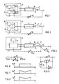
- the schematic structure of such a known measuring device is shown in FIG. 1.
- the pulse control circuit 1 alternately connects the catheter 3 to a pacemaker circuit 9 and the measuring circuit 10 controlling it.
- the pulse control circuit 1 two operating states of the system are set, with the pacemaker circuit 9 in the switch position 1a via the current conductor 3a and the electrodes 6 and 7 (housing of the pacemaker H) both detecting the ECG signal applied to the electrodes and emitting the stimulation pulse .
- the measuring circuit 10 scans the measuring probe 2 via the current conductors 3a and 3b.
- the catheter must therefore be designed with at least two poles between the pulse control circuit 1 of the pacemaker H and the measuring probe 2.
- bipolar catheters are thicker and accordingly less flexible and have a higher probability of failure than single-pole catheters.
- the production of two-pole catheters is more complex and expensive than the single-pole catheter.
- the object of the invention is therefore to design a measuring device of the type mentioned at the outset in such a way that the catheter can be made more flexible and reliable and its production is less expensive.
- the catheter is designed with a single current conductor between the pulse control circuit and the measuring probe and that the body tissue is used as a second current conductor between the measuring probe and the pulse control circuit via body electrodes. This eliminates the need for a power line in the catheter between the pulse control circuit and the measuring probe, so that it becomes more flexible, reliable and cost-effective.
- a measuring sensor can advantageously control the resistance of the measuring probe in such a way that changes in the current flow through the entire measuring circuit (measuring probe and power lines) are dependent on the measured value, but are independent of changes in resistance of the body tissue.
- the measuring sensor can be a resistor located in the measuring circuit, the change in resistance depending on the measured variable being very large compared to the changes in resistance of the current conductor acting as disturbing variables, so that the changes in the resistance value of the body tissue remain negligibly small in a certain measuring range.
- the measurement sensor controls a constant current regulator which is connected in series in the measurement circuit.
- the problem of eliminating the influence of changes in resistance of the body tissue can also be solved in that the measuring probe reacts to a measuring pulse emitted by the pulse control circuit with a change in resistance which has a measurement-dependent delay ⁇ t compared to the measuring pulse.
- This pulse-shaped change in resistance can be clearly detected compared to the slow changes in the resistance of the body tissue.
- the measuring probe converts the measured value into a digitally coded pulse sequence, according to which the resistance of the measuring probe changes. This digital information also remains unaffected by slow changes in the resistance in the measuring circuit.
- a further embodiment results in which the resistance of the measuring probe is frequency-modulated and the measured value can also be transmitted as frequency information independently of changes in the resistance of the body tissue.
- the measuring probe can advantageously be connected in series in the connecting line between the pulse control circuit and the electrode, the measuring probe containing a diode which for the stimulation pulses in the forward direction and for the measuring pulses in the reverse direction.
- the stimulation pulses are therefore not weakened by the resistance of the measuring probe which is dependent on the measured variable.
- the pulse control circuit emits a stimulation pulse via a capacitor, which discharges in the stimulation phase via the body resistance and which is subsequently recharged in the depolarization phase
- the current required for recharging which is part of the loss energy of the pacemaker, can advantageously be used can be used to control the measuring probe by the pulse control circuit also controlling the measuring pulse emitted in the reverse current direction to the stimulation pulse via the capacitor.
- FIG. 2 shows the principle of the arrangement for a pacemaker H.
- the pulse control circuit 1 which alternately connects the catheter 3 to the pacemaker circuit 9 or the measuring circuit 10, is connected via a single-wire current conductor 3a, which is arranged in the catheter 3, to one in the catheter 3 built-in probe 2 connected.
- the second connection of the measuring probe 2 is connected to a stimulation electrode 6 via a second section 5 of the current conductor, which is also arranged in the catheter 3.
- the body tissue which is characterized by the variable body resistance R K , and the housing electrode 7 serve as the return conductor to the pacemaker H.
- the catheter 3 has to be carried out continuously with only one current conductor 3a, so that its flexibility and reliability increases.
- FIG. 3 shows a further embodiment for a measuring device with the body tissue as a return line for the measuring probe 2.
- the catheter 3 has a so-called indifferent electrode 6a in addition to the stimulation electrode 6 in a known manner.
- indifferent electrodes are required if the stimulation and ECG measurement with the pacemaker H is to be carried out as free of interference as possible and therefore not over the body circle, but rather is carried out in the heart itself between the stimulation electrode 6 and the indifferent electrode 6a.
- the current flows through the measuring probe 2 via the line sections 3b and 5 to the indifferent electrode 6a and from there via the venous blood and the heart muscle R H to the stimulation electrode 6 back via the line 3a to the pulse control circuit 1.
- the Catheter 3 also has a second conductor 3b, but the advantage of this arrangement remains that the measuring probe 2 has only two connections.
- three connections are required, namely two connections to the pacemaker H and a further connection to the stimulation electrode 6.
- connections are complicated in the manufacture of the probe and the probability of failure is statistically increased by each connection.
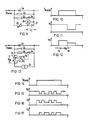
- FIG. 4 schematically shows a circuit variant for the measuring probe 2.
- This contains the parallel connection of a diode 2a and a measuring sensor, which in this case is shown as a resistance 2b dependent on the measured variable.
- the resistor 2b can be a temperature-dependent resistor, for example stood up.
- the diode 2a is polarized so that it is conductive for the stimulation pulse. This prevents the stimulation pulse from being weakened by a voltage drop across resistor 2b.
- the measurement is carried out by a resistance measurement with a constant current which is in the reverse direction of the diode 2a.
- the interference caused by fluctuating body resistance R K and the polarization voltage which arises at the electrode 6 with each stimulation are particularly disruptive.
- the influence of these disturbance variables can, however, be made negligible by the fact that the change in resistance of the resistor 2b which is dependent on the measured variable is large compared to the change in resistance of the connecting lines including body resistance R K which acts as disturbance variables.
- a controllable current source 2i is connected in parallel in the measuring probe 2 of the diode 2a.
- a second current source 2h supplies the measurement-dependent resistor 2b.
- a control input of the current source 2i is connected to the connection point between the current source 2h and the measurement-dependent resistor 2b.
- FIG. 6 shows the measuring pulse U S applied to the measuring probe 2.
- FIG. 7 shows the measurement-dependent control voltage U M present at the controllable current source 2i.
- the tax bare current source 2i supplies, based on this control voltage U M, a constant current I S which is proportional to the control voltage U M and thus the measured value and which can be measured in the measuring circuit 10. In a predetermined range, this constant current I S is independent of the resistance of the connecting lines including body resistance R K and of the polarization voltage at the electrodes 6, 7.
- a further possibility for eliminating the influences of changing body resistance R K and polarization voltages is that the measuring probe reacts to a measuring pulse U S emitted by the evaluation circuit with a change in resistance which has a measured value-dependent delay compared to the measuring pulse U S.
- a circuit example for realizing this measurement value acquisition is shown in FIG.
- the diode 2a is a resistor 2c, the series connection of a resistor 2d and a switch 2e and the series connection of the measurement-dependent resistor 2b and a capacitor 2f are connected in parallel.
- the switch 2e is controlled via a threshold switch 2k by the voltage U c present at the capacitor 2f.
- the measuring pulse U S is thus present at the measuring probe 2.
- the capacitor 2f is charged via the variable-dependent resistor 2b.
- the voltage U c at the capacitor 2f is reached the threshold of switch 2k that closes switch 2e.
- the resistor 2d is now also effective, so that the probe resistance R S and thus the voltage of the measuring pulse U S drop.
- the time span ⁇ t between the start t U of the measuring pulse I Konst and the time t M of the voltage drop of the measuring pulse U S thus represents a measure of the measured variable which can be detected without any problems regardless of the slow changes in the resistance R K of the body tissue and of polarization voltages can.
- FIG. 13 shows schematically an embodiment of such an arrangement.
- the diode 2a is a resistor 2c, the series connection of a resistor 2d and a switch 2e and the series connection of the measurement-dependent resistor 2b and a constant current source 2h are connected in parallel.
- An analog-digital converter 2g taps the measured-value-dependent control voltage U M from the measured-value-dependent resistor 2b on the input side and controls the switch 2e on the output side.
- a measured value-dependent control voltage U M is present at the input of the analog-digital converter 2g.
- This voltage is now encoded in a digital value which controls the switch 2e and thus switches on the resistor 2d accordingly.
- the digital information is therefore transmitted to the evaluation circuit on the basis of the changes in the probe resistance R S or the probe voltage U S shown in FIG.
- the analog-digital converter 2g can be designed so that after each measuring pulse I Konst it first emits a start pulse and then transmits the measured value, for example, as shown in FIGS. 14-16, in the form of binary information.
- FIG. 17 shows the digital measuring voltage U D formed therefrom.
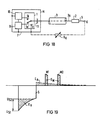
- FIG. 18 shows an exemplary embodiment in which the pacemaker H contains a capacitor 11, via which the stimulation pulse is conducted.
- the single-pole measuring catheter 3 With the single-pole measuring catheter 3 according to the invention, it is possible in a simple manner to use the energy which is otherwise lost when a capacitor 11 is recharged, which is used in the stimulation circuit of the pacemaker circuit 9, for the measurement.
- the capacitor 11 is additionally connected between the pulse control circuit 1 and the current conductor 3a and the pulse control circuit 1 has a third switch position 1c in order to discharge the residual charge of the capacitor 11 to ground after the measurement phase.
- FIG. 19 illustrates the effect of the measurement pulse control on the basis of the voltage profile on the capacitor 11 on the catheter side.
- S denotes the stimulation pulse delivered via the capacitor 11.
- the power loss Ev contained in the voltage drop of the stimulation pulse S from U S1 to U S2 by discharging the capacitor 11 via the body resistance R K is normally compensated for in the recharging phase (dashed line).
- the charging power E A required for this can be used by corresponding measuring pulse control, for example for two measuring pulses M1, M2 with the power requirement E M.
Abstract
Die Meßvorrichtung enthält eine Pulssteuerschaltung (1), an die über einen Katheter (3) mit Stromleitern (3a,b) eine Meßsonde (2) angeschlossen ist. Der Katheter (3) enthält einen einzigen Stromleiter (3a) zwischen Pulssteuerschaltung (1) und Meßsonde (2). Das Körpergewebe wird als zweiter Stromleiter zwischen Meßsonde (2) und Pulssteuerschaltung (1) benutzt. Es wird festgelegt, unter welchen Voraussetzungen das Körpergewebe als Stromleiter genutzt werden kann. Weiterhin werden verschiedene Lösungen angegeben, um bei der Messung den Einfluß von Widerstandsschwankungen des Körpergewebes zu eliminieren.The measuring device contains a pulse control circuit (1) to which a measuring probe (2) is connected via a catheter (3) with current conductors (3a, b). The catheter (3) contains a single current conductor (3a) between the pulse control circuit (1) and measuring probe (2). The body tissue is used as a second conductor between the measuring probe (2) and pulse control circuit (1). The conditions under which the body tissue can be used as an electrical conductor are specified. Furthermore, various solutions are given in order to eliminate the influence of resistance fluctuations in the body tissue during the measurement.
Description
Die Erfindung betrifft eine Meßvorrichtung zur Steuerung implantierbarer Körperersatzteile mit einer Pulssteuerschaltung, an die über einen Katheter mit Stromleitern eine Meßsonde angeschlossen ist.The invention relates to a measuring device for controlling implantable body parts with a pulse control circuit, to which a measuring probe is connected via a catheter with current conductors.
Eine derartige Meßvorrichtung zur Erfassung der Blutsauerstoffsättigung für die Frequenzregelung eines Herzschrittmachers ist beispielsweise aus der DE-PS 31 52 963 bekannt. Der schematische Aufbau einer solchen bekannten Meßvorrichtung ist in Fig. 1 dargestellt.Such a measuring device for detecting the blood oxygen saturation for the frequency control of a pacemaker is known for example from DE-PS 31 52 963. The schematic structure of such a known measuring device is shown in FIG. 1.
Bei einem Herzschrittmachersystem der bekannten Art, bestehend aus dem Herzschrittmacher H und dem kombinierten Meß- und Stimulationskatheter 3 werden von einer Pulssteuerschaltung 1 der Katheter 3 abwechselnd mit einer Schrittmacherschaltung 9 und der sie steuernden Meßschaltung 10 verbunden. Mit der Pulssteuerschaltung 1 werden dabei zwei Betriebszustände des Systems eingestellt, wobei bei Schalterstellung 1a die Schrittmacherschaltung 9 über den Stromleiter 3a und die Elektroden 6 und 7 (Gehäuse des Herzschrittmachers H) sowohl das an den Elektroden anliegende EKG-Signal erfaßt als auch den Stimulationsimpuls abgibt. Bei Schalterstellung 1b der Pulssteuerschaltung 1 tastet die Meßschaltung 10 über die Stromleiter 3a und 3b die Meßsonde 2 ab.In a cardiac pacemaker system of the known type, consisting of the cardiac pacemaker H and the combined measurement and
Der Katheter muß daher zumindest zwischen Pulssteuerschaltung 1 des Herzschrittmachers H und Meßsonde 2 zweipolig ausgeführt werden. Zweipolige Katheter sind jedoch dicker und dementspre chend weniger flexibel und haben eine höhere Ausfallwahrscheinlichkeit als einpolige Katheter. Außerdem ist die Herstellung zweipoliger Meßkatheter aufwendiger und teurer als die einpoliger Katheter.The catheter must therefore be designed with at least two poles between the pulse control circuit 1 of the pacemaker H and the
Aufgabe der Erfindung ist es daher, eine Meßvorrichtung der eingangs genannten Art so auszugestalten, daß der Katheter flexibler und zuverlässiger gestaltet werden kann und seine Herstellung kostengünstiger ist.The object of the invention is therefore to design a measuring device of the type mentioned at the outset in such a way that the catheter can be made more flexible and reliable and its production is less expensive.
Diese Aufgabe wird erfindungsgemäß dadurch gelöst, daß der Katheter mit einem einzigen Stromleiter zwischen Pulssteuerschaltung und Meßsonde ausgeführt ist und daß über Körperelektroden das Körpergewebe als zweiter Stromleiter zwischen Meßsonde und Pulssteuerschaltung benutzt wird. Damit entfällt im Katheter zwischen Pulssteuerschaltung und Meßsonde eine Stromleitung, so daß dieser flexibler, zuverlässiger und kostengünstiger wird.This object is achieved in that the catheter is designed with a single current conductor between the pulse control circuit and the measuring probe and that the body tissue is used as a second current conductor between the measuring probe and the pulse control circuit via body electrodes. This eliminates the need for a power line in the catheter between the pulse control circuit and the measuring probe, so that it becomes more flexible, reliable and cost-effective.
Vorteilhafterweise kann ein Meßsensor den Widerstand der Meßsonde so steuern, daß Änderungen des Stromflusses durch den gesamten Meßkreis (Meßsonde und Stromleitungen) abhängig vom Meßwert, aber unabhängig von Widerstandsänderungen des Körpergewebes sind.A measuring sensor can advantageously control the resistance of the measuring probe in such a way that changes in the current flow through the entire measuring circuit (measuring probe and power lines) are dependent on the measured value, but are independent of changes in resistance of the body tissue.
Bei einer vorteilhaft einfachen Ausgestaltung kann der Meßsensor ein im Meßkreis liegender Widerstand sein, dessen meßgrößenabhängige Widerstandsänderung sehr groß gegenüber den als Störgrößen wirkenden Widerstandsänderungen der Stromleiter ist, so daß die Änderungen des Widerstandswertes des Körpergewebes in einem bestimmten Meßbereich vernachlässigbar klein bleiben.In an advantageously simple embodiment, the measuring sensor can be a resistor located in the measuring circuit, the change in resistance depending on the measured variable being very large compared to the changes in resistance of the current conductor acting as disturbing variables, so that the changes in the resistance value of the body tissue remain negligibly small in a certain measuring range.
Eine weitere Möglichkeit, das Meßergebnis vom Widerstand des Körpergewebes unabhängig zu machen, besteht darin, daß der Meßsensor einen seriell im Meßkreis liegenden Konstantstromregler steuert.Another possibility of making the measurement result independent of the resistance of the body tissue is that the measurement sensor controls a constant current regulator which is connected in series in the measurement circuit.
Das Problem, den Einfluß von Widerstandsänderungen des Körpergewebes auszuschalten, kann auch dadurch gelöst werden, daß die Meßsonde auf einen von der Pulssteuerschaltung ausgesandten Meßimpuls mit einer Widerstandsänderung reagiert, die gegenüber dem Meßimpuls eine meßwertabhängige Verzögerung Δt aufweist. Diese pulsförmige Widerstandsänderung ist gegenüber den langsamen Änderungen des Widerstands des Körpergewebes eindeutig erfaßbar.The problem of eliminating the influence of changes in resistance of the body tissue can also be solved in that the measuring probe reacts to a measuring pulse emitted by the pulse control circuit with a change in resistance which has a measurement-dependent delay Δt compared to the measuring pulse. This pulse-shaped change in resistance can be clearly detected compared to the slow changes in the resistance of the body tissue.
In einer weiteren alternativen Ausführungsform setzt die Meßsonde den Meßwert in eine digital codierte Impulsfolge um, entsprechend der sich der Widerstand der Meßsonde ändert. Diese digitale Information bleibt ebenfalls von langsamen Änderungen des Widerstands im Meßkreis unbeeinflußt.In a further alternative embodiment, the measuring probe converts the measured value into a digitally coded pulse sequence, according to which the resistance of the measuring probe changes. This digital information also remains unaffected by slow changes in the resistance in the measuring circuit.
Wird anstelle der Analog-Digitalwandlerschaltung ein Analog-Frequenzwandler verwendet, ergibt sich eine weitere Ausführungsform, bei der der Widerstand der Meßsonde frequenzmoduliert wird und der Meßwert als Frequenzinformation ebenso unabhängig von Widerstandsänderungen des Körpergewebes übertragen werden kann.If an analog-to-frequency converter is used instead of the analog-to-digital converter circuit, a further embodiment results in which the resistance of the measuring probe is frequency-modulated and the measured value can also be transmitted as frequency information independently of changes in the resistance of the body tissue.
Bei einer Meßvorrichtung für einen Herzschrittmacher, bei dem die Pulssteuerschaltung zusätzlich Stimulationsimpulse über einen Katheter mit einer Stimulationselektrode an den Herzmuskel abgibt, kann die Meßsonde vorteilhafterweise seriell in die Verbindungsleitung zwischen Pulssteuerschaltung und Elektrode geschaltet sein, wobei die Meßsonde eine Diode enthält, die für die Stimulationsimpulse in Durchlaßrichtung und für die Meßimpulse in Sperrichtung liegt. Damit werden die Stimulationsimpulse nicht durch den meßgrößenabhängigen Widerstand der Meßsonde geschwächt.In a measuring device for a pacemaker, in which the pulse control circuit additionally emits stimulation pulses to the heart muscle via a catheter with a stimulation electrode, the measuring probe can advantageously be connected in series in the connecting line between the pulse control circuit and the electrode, the measuring probe containing a diode which for the stimulation pulses in the forward direction and for the measuring pulses in the reverse direction. The stimulation pulses are therefore not weakened by the resistance of the measuring probe which is dependent on the measured variable.
Bei einer Meßvorrichtung, bei der die Pulssteuerschaltung einen Stimulationsimpuls über einen Kondensator abgibt, der sich in der Stimulationsphase über den Körperwiderstand entlädt und der anschließend in der Depolarisationsphase wieder aufgeladen wird, kann der zur Wiederaufladung nötige Strom, der Teil der Verlustenergie des Herzschrittmachers ist, vorteilhafterweise zur Ansteuerung der Meßsonde genutzt werden, indem die Pulssteuerschaltung den in umgekehrter Stromrichtung zum Stimulationsimpuls abgegebenen Meßimpuls ebenfalls über den Kondensator steuert.In a measuring device in which the pulse control circuit emits a stimulation pulse via a capacitor, which discharges in the stimulation phase via the body resistance and which is subsequently recharged in the depolarization phase, the current required for recharging, which is part of the loss energy of the pacemaker, can advantageously be used can be used to control the measuring probe by the pulse control circuit also controlling the measuring pulse emitted in the reverse current direction to the stimulation pulse via the capacitor.
Ausführungsbeispiele der Erfindung werden nachfolgend anhand der Figuren 2 bis 19 näher erläutert.Exemplary embodiments of the invention are explained in more detail below with reference to FIGS. 2 to 19.
Figur 2 zeigt das Prinzip der Anordnung für einen Herzschrittmacher H. Die Pulssteuerschaltung 1, die den Katheter 3 abwechselnd an die Schrittmacherschaltung 9 oder die Meßschaltung 10 schaltet, ist über einen einadrigen Stromleiter 3a, der in dem Katheter 3 angeordnet ist, mit einem Anschluß einer in den Katheter 3 eingebauten Meßsonde 2 verbunden. Der zweite Anschluß der Meßsonde 2 ist über einen zweiten Abschnitt 5 des Stromleiters, der ebenfalls in dem Katheter 3 angeordnet ist, mit einer Stimulationselektrode 6 verbunden. Als Rückleiter zum Herzschrittmacher H dient das Körpergewebe, das durch den variablen Körperwiderstand RK gekennzeichnet ist, und die Gehäuseelektrode 7. Damit werden sowohl Stimulationsimpulse als auch Meßwerte über den Stromleiter 3a und 5 sowie das Körper gewebe (gestrichelte Linie) übertragen. Der Katheter 3 muß durchgehend nur mit einem Stromleiter 3a ausgeführt werden, so daß seine Flexibilität und Zuverlässigkeit steigt.Figure 2 shows the principle of the arrangement for a pacemaker H. The pulse control circuit 1, which alternately connects the
Figur 3 zeigt eine weitere Ausführungsform für eine Meßvorrichtung mit dem Körpergewebe als Rückleitung für die Meßsonde 2. In diesem Falle weist der Katheter 3 in bekannter Weise zusätzlich zur Stimulationselektrode 6 eine sogenannte indifferente Elektrode 6a auf. Solche indifferenten Elektroden werden benötigt, wenn die Stimulation und EKG-Messung mit dem Herzschrittmacher H möglichst störungsfrei und deshalb nicht über den Körperkreis vorgenommen werden soll, sondern im Herzen selbst zwischen Stimulationselektrode 6 und indifferenter Elektrode 6a durchgeführt wird. In diesem Falle erfolgt der Stromfluß durch die Meßsonde 2 über die Leitungsabschnitte 3b und 5 zur indifferenten Elektrode 6a und von da über das venöse Blut und den Herzmuskel RH zur Stimulationselektrode 6 zurück über die Leitung 3a zur Pulssteuerschaltung 1. In diesem Falle weist zwar der Katheter 3 auch einen zweiten Leiter 3b auf, als Vorteil dieser Anordnung bleibt jedoch, daß die Meßsonde 2 lediglich zwei Anschlüsse aufweist. Beim Stand der Technik gemäß Figur 1 sind dagegen drei Anschlüsse erforderlich, nämlich zwei Anschlüsse zum Herzschrittmacher H und ein weiterführender Anschluß zur Stimulationselektrode 6. In der Sondenherstellung sind jedoch Anschlüsse kompliziert und die Ausfallwahrscheinlichkeit wird durch jeden Anschluß statistisch erhöht.FIG. 3 shows a further embodiment for a measuring device with the body tissue as a return line for the
Figur 4 zeigt schematisch eine Schaltungsvariante für die Meßsonde 2. Diese enthält die Parallelschaltung einer Diode 2a und eines Meßsensors, der in diesem Falle als meßgrößenabhängiger Widerstand 2b dargestellt ist. Für eine Temperaturmessung kann der Widerstand 2b z.B. ein temperaturabhängiger Wider stand sein. Die Diode 2a ist so gepolt, daß sie für den Stimulationsimpuls leitend ist. Damit wird verhindert, daß der Stimulationsimpuls durch einen Spannungsabfall am Widerstand 2b geschwächt wird.FIG. 4 schematically shows a circuit variant for the
Die Messung wird durch eine Widerstandsmessung mit einem Konstantstrom durchgeführt, der in Sperrichtung der Diode 2a liegt.The measurement is carried out by a resistance measurement with a constant current which is in the reverse direction of the
Bei dieser einfachen Ausführungsform ist vor allem der Störeinfluß durch schwankenden Körperwiderstand RK sowie die bei jeder Stimulation an der Elektrode 6 entstehende Polarisationsspannung störend. Der Einfluß dieser Störgrößen kann jedoch dadurch vernachlässigbar klein gemacht werden, daß die meßgrößenabhängige Widerstandsänderung des Widerstands 2b groß gegenüber den als Störgrößen wirkenden Widerstandsänderungen der Verbindungsleitungen einschließlich Körperwiderstand RK ist.In this simple embodiment, the interference caused by fluctuating body resistance R K and the polarization voltage which arises at the
Eine weitere Möglichkeit zur Eliminierung des Störeinflusses des schwankenden Körperwiderstandes RK ist in Figur 5 dargestellt. Dabei ist in der Meßsonde 2 der Diode 2a eine steuerbare Stromquelle 2i parallel geschaltet. Eine zweite Stromquelle 2h versorgt den meßgrößenabhängigen Widerstand 2b. Ein Steuereingang der Stromquelle 2i ist mit dem Verbindungspunkt von Stromquelle 2h und meßgrößenabhängigem Widerstand 2b verbunden.A further possibility for eliminating the disturbing influence of the fluctuating body resistance R K is shown in FIG. 5. A controllable
Bei Beaufschlagung der Schaltung mit einem Meßimpuls US fließt durch die Stromquelle 2h ein Konstantstrom und erzeugt an dem meßwertabhängigen Widerstand 2b eine meßwertabhängige Steuerspannung UM, die die steuerbare Stromquelle 2i steuert. In Figur 6 ist der an der Meßsonde 2 anstehende Meßimpuls US dargestellt. Figur 7 zeigt die an der steuerbaren Stromquelle 2i anstehende meßwertabhängige Steuerspannung UM. Die steuer bare Stromquelle 2i liefert aufgrund dieser Steuerspannung UM einen der Steuerspannung UM und damit dem Meßwert proportionalen Konstantstrom IS, der in der Meßschaltung 10 gemessen werden kann. Dieser Konstantstrom IS ist in einem vorgegeben Bereich unabhängig vom Widerstand der Verbindungsleitungen einschließlich Körperwiderstand RK und von den Polarisationsspannung an den Elektroden 6,7.When a measurement pulse U S is applied to the circuit, a constant current flows through the
Eine weitere Möglichkeit, die Einflüsse von sich änderndem Körperwiderstand RK und Polarisationsspannungen zu eliminieren, besteht darin, daß die Meßsonde auf einen von der Auswerteschaltung ausgesandten Meßimpuls US mit einer Widerstandsänderung reagiert, die gegenüber dem Meßimpuls US eine meßwertabhängige Verzögerung aufweist. Ein Schaltungsbeispiel zur Realisierung dieser Meßwerterfassung ist in Figur 9 dargestellt. Dabei ist der Diode 2a ein Widerstand 2c, die Reihenschaltung eines Widerstandes 2d und eines Schalters 2e und die Reihenschaltung des meßgrößenabhängigen Widerstands 2b und eines Kondensators 2f parallel geschaltet. Der Schalter 2e wird über einen Schwellwertschalter 2k von der am Kondensator 2f anstehenden Spannung Uc gesteuert.A further possibility for eliminating the influences of changing body resistance R K and polarization voltages is that the measuring probe reacts to a measuring pulse U S emitted by the evaluation circuit with a change in resistance which has a measured value-dependent delay compared to the measuring pulse U S. A circuit example for realizing this measurement value acquisition is shown in FIG. The
Die Funktion der Schaltung wird nachfolgend anhand der Diagramme nach den Figuren 10-12 erläutert. Wenn man die Schaltung mit einem Konstantstrom-Meßimpuls (IKonst) entgegengesetzt zur Leitrichtung der Diode 2a beaufschlagt, so ist der Schalter 2e zunächst noch geöffnet und der gesamte wirksame Sondenwiderstand RS der Meßsonde 2 wird im wesentlichen durch den Widerstand 2c bestimmt.The function of the circuit is explained below using the diagrams according to FIGS. 10-12. If the circuit is charged with a constant current measuring pulse (I Konst ) opposite to the direction of the
Damit liegt an der Meßsonde 2 der Meßimpuls US. Gleichzeitig wird der Kondensator 2f über den meßgrößenabhängigen Widerstand 2b aufgeladen. Nach einer Zeit Δ t, die vom Widerstandswert des meßgrößenabhängigen Widerstands 2b und damit von der Meßgröße abhängig ist, erreicht die Spannung Uc am Kondensator 2f den Schwellwert des Schalters 2k, der den Schalter 2e schließt. Damit wird nun auch der Widerstand 2d wirksam, so daß der Sondenwiderstand RS und damit auch die Spannung des Meßimpulses US abfällt. Die Zeitspanne Δ t zwischen Beginn tU des Meßimpulses IKonst und dem Zeitpunkt tM des Spannungsabfalls des Meßimpulses US stellt somit ein Maß für die Meßgröße dar, das problemlos unabhängig von den langsamen Änderungen des Widerstandes RK des Körpergewebes und von Polarisationsspannungen erfaßt werden kann.The measuring pulse U S is thus present at the
Schließlich gibt es auch die Möglichkeit, die Meßgröße unabhängig von Widerstandsschwankungen des Körpergewebes und von Polarisationsspannungen digital zu übertragen. Figur 13 zeigt schematisch ein Ausführungsbeispiel für eine solche Anordnung. Dabei ist der Diode 2a ein Widerstand 2c, die Reihenschaltung eines Widerstands 2d und eines Schalters 2e sowie die Reihenschaltung des meßgrößenabhängigen Widerstands 2b und einer Konstantstromquelle 2h parallel geschaltet. Ein Analog-Digitalwandler 2g greift eingangsseitig die meßwertabhängige Steuerspannung UM vom meßgrößenabhängigen Widerstand 2b ab und steuert ausgangsseitig den Schalter 2e.Finally, there is also the possibility of digitally transmitting the measured variable independently of fluctuations in the resistance of the body tissue and of polarization voltages. Figure 13 shows schematically an embodiment of such an arrangement. The
Wenn man diese Schaltung mit einem Meßimpuls IKonst entgegengesetzt zur Leitrichtung der Diode 2a beaufschlagt, so steht am Eingang des Analog-Digital-Wandlers 2g eine meßwertabhängige Steuerspannung UM an. Diese Spannung wird nun in einen Digitalwert codiert, der den Schalter 2e steuert und damit entsprechend den Widerstand 2d zuschaltet. Die digitale Information wird daher zur Auswerteschaltung aufgrund der in Figur 15 dargestellten Änderungen des Sondenwiderstands RS bzw. der Sondenspannung US übertragen. Dabei kann der Analog-Digital-Wandler 2g so ausgeführt sein, daß er nach jedem Meßimpuls IKonst zunächst einen Startimpuls abgibt und dann den erfaßten Meßwert z.B., wie in den Figuren 14-16 dargestellt, in Form einer Binär-Information überträgt. Figur 17 zeigt die daraus gebildete digitale Meßspannung UD.If this circuit is subjected to a measuring pulse I Konst opposite to the direction of the
Figur 18 zeigt ein Ausführungsbeispiel, bei dem der Herzschrittmacher H einen Kondensator 11 enthält, über den der Stimulationsimpuls geleitet wird.FIG. 18 shows an exemplary embodiment in which the pacemaker H contains a capacitor 11, via which the stimulation pulse is conducted.
Mit dem erfindungsgemäßen einpoligen Meßkatheter 3 ist es auf einfache Weise möglich, die Energie, die beim Wiederaufladen eines Kondensators 11, der in dem Stimulationskreis der Schrittmacherschaltung 9 genutzt wird, sonst verloren geht, für die Messung zu nutzen.With the single-
Gegenüber dem Ausführungsbeispiel nach Figur 2 ist zusätzlich der Kondensator 11 zwischen die Pulssteuerschaltung 1 und den Stromleiter 3a geschaltet und die Pulssteuerschaltung 1 weist eine dritte Schalterstellung 1c auf, um nach der Meßphase die Restladung des Kondensators 11 an Masse abzuleiten.Compared to the exemplary embodiment according to FIG. 2, the capacitor 11 is additionally connected between the pulse control circuit 1 and the
Figur 19 verdeutlicht anhand des katheterseitigen Spannungsverlaufs am Kondensator 11 die Wirkung der Meßimpulssteuerung. Dabei ist mit S der über den Kondensator 11 abgegebene Stimulationsimpuls bezeichnet. Die im Spannungsabfall des Stimulationsimpulses S von US1 nach US2 enthaltene Verlustleistung Ev durch Entladung des Kondensators 11 über den Körperwiderstand RK wird normalerweise in der Wiederaufladephase (gestrichelte Linie) ausgeglichen. Die dazu nötige Aufladeleistung EA kann durch entsprechende Meßimpulssteuerung zum Beispiel für zwei Meßimpulse M1,M2 mit dem Leistungsbedarf EM genutzt werden.FIG. 19 illustrates the effect of the measurement pulse control on the basis of the voltage profile on the capacitor 11 on the catheter side. S denotes the stimulation pulse delivered via the capacitor 11. The power loss Ev contained in the voltage drop of the stimulation pulse S from U S1 to U S2 by discharging the capacitor 11 via the body resistance R K is normally compensated for in the recharging phase (dashed line). The charging power E A required for this can be used by corresponding measuring pulse control, for example for two measuring pulses M1, M2 with the power requirement E M.
Claims (11)
dadurch gekennzeichnet,
daß der Katheter (3) mit einem einzigen Stromleiter (3a) zwischen Pulssteuerschaltung (1) und Meßsonde (2) ausgeführt ist und daß über Körperelektroden (6,7) das Körpergewebe als zweiter Stromleiter zwischen Meßsonde (2) und Pulssteuerschaltung (1) benutzt wird.1. Measuring device for controlling implantable body parts with a pulse control circuit (1), to which a measuring probe (2) is connected via a catheter (3) with current conductors (3a, b),
characterized by
that the catheter (3) is designed with a single current conductor (3a) between the pulse control circuit (1) and the measuring probe (2) and that the body tissue is used as the second current conductor between the measuring probe (2) and the pulse control circuit (1) via body electrodes (6,7) becomes.
dadurch gekennzeichnet,
daß ein Meßsensor (2b) den Widerstand der Meßsonde (2) so steuert, daß Änderungen des Stromflusses durch den gesamten Meßkreis (Meßsonde und Stromleitungen) abhängig vom Meßwert, aber unabhängig vom Widerstand (RK) des Körpergewebes sind.2. Measuring device according to claim 1,
characterized by
that a measuring sensor (2b) controls the resistance of the measuring probe (2) so that changes in the current flow through the entire measuring circuit (measuring probe and power lines) are dependent on the measured value, but independent of the resistance (R K ) of the body tissue.
dadurch gekennzeichnet,
daß ein von der Pulssteuerschaltung (1) abgegebener Meßimpuls so kurz und energiearm ist, daß keinerlei Eigenaktivität des Körpergewebes ausgelöst wird.3. Measuring device according to claim 1 or 2,
characterized by
that a measuring pulse emitted by the pulse control circuit (1) is so short and low in energy that no intrinsic activity of the body tissue is triggered.
dadurch gekennzeichnet,
daß der Stromkreis über das Körpergewebe nach dem(n) Meßimpuls(en) solange geschlossen bleibt, bis sich die nach der Meßphase an den Elektroden (6,7) vorhandenen Polarisationsspannungen abgebaut haben.4. Measuring device according to one of claims 1 to 3,
characterized by
that the circuit via the body tissue remains closed after the measuring pulse (s) until the polarization voltages present on the electrodes (6, 7) after the measuring phase have reduced.
dadurch gekennzeichnet,
daß der Meßsensor (2b) ein im Meßkreis liegender Widerstand ist, dessen meßgrößenabhängige Widerstandsänderung sehr groß gegenüber den als Störgrößen wirkenden Widerstandsänderungen der Verbindungsleitungen ist.5. Measuring device according to one of claims 1 to 4,
characterized by
that the measuring sensor (2b) is a resistor in the measuring circuit, the change in resistance depending on the measured variable is very large compared to the changes in resistance of the connecting lines which act as disturbing variables.
dadurch gekennzeichnet,
daß der Meßsensor (2b) einen seriell im Meßkreis liegenden Konstantstromregler (2i) steuert.6. Measuring device according to one of claims 1 to 4,
characterized by
that the measuring sensor (2b) controls a constant current controller (2i) lying in series in the measuring circuit.
dadurch gekennzeichnet,
daß die Meßsonde (2) auf einen von der Pulssteuerschaltung (1) ausgesandten Meßimpuls (IKonst) mit einer Widerstandsänderung reagiert, die gegenüber dem Meßimpuls (IKonst) eine meßwertabhängige Verzögerung aufweist.7. Measuring device according to one of claims 1 to 4,
characterized by
that the measuring probe (2) reacts to a measuring pulse (I Konst ) emitted by the pulse control circuit (1) with a change in resistance, which has a measured value-dependent delay compared to the measuring pulse (I Konst ).
dadurch gekennzeichnet,
daß die Meßsonde (2) den Meßwert in eine digital codierte Impulsfolge umsetzt, entsprechend der sich der Widerstand der Meßsonde (2) ändert.8. Measuring device according to one of claims 1 to 4,
characterized by
that the measuring probe (2) converts the measured value into a digitally coded pulse sequence, according to which the resistance of the measuring probe (2) changes.
dadurch gekennzeichnet,
daß die Meßsonde (2) den Meßwert in eine Frequenz umsetzt, entsprechend der sich der Widerstand der Meßsonde (2) ändert.9. Measuring device according to claim 1,
characterized by
that the measuring probe (2) converts the measured value into a frequency according to which the resistance of the measuring probe (2) changes.
dadurch gekennzeichnet,
daß die Meßsonde (2) in die Verbindungsleitung (3a,5) zwischen Pulssteuerschaltung (1) und Elektrode (6) seriell geschaltet ist und daß die Meßsonde (2) eine Diode (2a) enthält, die für die Stimulationsimpulse in Durchlaßrichtung und für die Meßimpulse in Sperrichtung liegt.10. Measuring device according to one of claims 1 to 9 for a pacemaker (H), wherein the pulse control circuit (1) additionally emits stimulation pulses via the catheter (3) with current conductor (3a) and stimulation electrode (6) to the heart muscle (R H ),
characterized by
that the measuring probe (2) is connected in series in the connecting line (3a, 5) between the pulse control circuit (1) and the electrode (6) and that the measuring probe (2) contains a diode (2a) which is used for the stimulation pulses in the forward direction and for the Measuring pulses in the reverse direction.
wobei die Pulssteuerschaltung (1) einen Stimulationsimpuls über einen Kondensator (CS) abgibt, der sich in der Stimulationsphase über den Körperwiderstand (RK) entlädt und der anschließend in der Depolarisationsphase wieder aufgeladen wird,
dadurch gekennzeichnet,
daß der zur Wiederaufladung nötige Strom, der Teil der Verlustenergie des Herzschrittmachers (H) ist, zur Ansteuerung der Meßsonde (2) genutzt wird, indem die Pulssteuerschaltung (1) den in umgekehrter Stromrichtung zum Stimulationsimpuls abgegebenen Meßimpuls ebenfalls über den Kondensator (CS) führt.11. Measuring device according to claim 10,
wherein the pulse control circuit (1) emits a stimulation pulse via a capacitor (C S ) which discharges in the stimulation phase via the body resistance (R K ) and which is subsequently recharged in the depolarization phase,
characterized by
that the current required for recharging, which is part of the lost energy of the pacemaker (H), is used to control the measuring probe (2) by the pulse control circuit (1) also supplying the measuring pulse emitted in the opposite direction to the stimulation pulse via the capacitor (C S ) leads.
Applications Claiming Priority (2)
| Application Number | Priority Date | Filing Date | Title |
|---|---|---|---|
| DE3627933 | 1986-08-18 | ||
| DE3627933 | 1986-08-18 |
Publications (2)
| Publication Number | Publication Date |
|---|---|
| EP0256437A1 true EP0256437A1 (en) | 1988-02-24 |
| EP0256437B1 EP0256437B1 (en) | 1991-09-04 |
Family
ID=6307606
Family Applications (1)
| Application Number | Title | Priority Date | Filing Date |
|---|---|---|---|
| EP87111352A Expired - Lifetime EP0256437B1 (en) | 1986-08-18 | 1987-08-05 | Measuring device for controlling implantable body substitutes |
Country Status (4)
| Country | Link |
|---|---|
| US (1) | US4870967A (en) |
| EP (1) | EP0256437B1 (en) |
| JP (1) | JPH0832260B2 (en) |
| DE (1) | DE3772669D1 (en) |
Families Citing this family (9)
| Publication number | Priority date | Publication date | Assignee | Title |
|---|---|---|---|---|
| FR2624024A1 (en) * | 1987-12-07 | 1989-06-09 | Brehier Jacques | CARDIAC STIMULATOR AND METHOD FOR ADJUSTING THE STIMULATOR |
| DE58907652D1 (en) * | 1988-02-05 | 1994-06-16 | Siemens Ag | METHOD FOR ADJUSTING THE STIMULATION FREQUENCY OF A HEART PACEMAKER TO THE STRESS OF A PATIENT. |
| DE4100568A1 (en) * | 1991-01-11 | 1992-07-16 | Fehling Guido | DEVICE FOR MONITORING A PATIENT FOR REPELLATION REACTIONS OF AN IMPLANTED ORGAN |
| EP0557550B1 (en) * | 1992-02-26 | 1996-12-27 | Pacesetter AB | Rate adaptive cardiac pacemaker |
| US5454377A (en) * | 1993-10-08 | 1995-10-03 | The Ohio State University | Method for measuring the myocardial electrical impedance spectrum |
| SE9600511D0 (en) * | 1996-02-12 | 1996-02-12 | Pacesetter Ab | Bipolar sensor electrode |
| US6269264B1 (en) * | 1996-12-13 | 2001-07-31 | Pacesetter, Inc. | Method for measuring impedance in the body |
| JP4781898B2 (en) * | 2006-04-28 | 2011-09-28 | 株式会社コロナ | heater |
| US20110227694A1 (en) * | 2008-11-24 | 2011-09-22 | Koninklijke Philips Electronics N.V. | Catheter interfacing |
Citations (4)
| Publication number | Priority date | Publication date | Assignee | Title |
|---|---|---|---|---|
| DE1573240A1 (en) * | 1966-07-05 | 1970-11-26 | Rudolf Koch | Thermal probe for measuring the heart blood temperature |
| EP0096464A1 (en) * | 1982-05-19 | 1983-12-21 | Purdue Research Foundation | Exercise responsive cardiac pacemaker |
| EP0133828A1 (en) * | 1983-08-02 | 1985-03-06 | BIOVALLEES Société Anonyme: | Method of controlling a cardiac pacemaker |
| WO1985005279A1 (en) * | 1984-05-24 | 1985-12-05 | Eckhard Alt | Load-related variable frequency pacemaker |
Family Cites Families (8)
| Publication number | Priority date | Publication date | Assignee | Title |
|---|---|---|---|---|
| JPS5645629A (en) * | 1979-09-20 | 1981-04-25 | Olympus Optical Co | System for transmitting data of endoscope |
| DE3107128C2 (en) * | 1981-02-26 | 1984-07-05 | Heinze, Roland, Dipl.-Ing., 8000 München | Control circuit for adapting the stimulation frequency of a cardiac pacemaker to the load on a patient |
| US4406288A (en) * | 1981-04-06 | 1983-09-27 | Hugh P. Cash | Bladder control device and method |
| US4688575A (en) * | 1982-03-12 | 1987-08-25 | Duvall Wilbur E | Muscle contraction stimulation |
| DE3428975A1 (en) * | 1984-08-06 | 1986-02-13 | Michael S. 8113 Kochel Lampadius | BREATH-CONTROLLED HEART PACEMAKER |
| US4688574A (en) * | 1985-06-17 | 1987-08-25 | Minnesota Mining And Manufacturing Company | Electrical stimulator for biological tissue having mode control |
| US4730618A (en) * | 1986-06-16 | 1988-03-15 | Siemens Aktiengesellschaft | Cardiac pacer for pacing a human heart and pacing method |
| US4787389A (en) * | 1987-07-16 | 1988-11-29 | Tnc Medical Devices Pte. Ltd. | Using an implantable antitachycardia defibrillator circuit |
-
1987
- 1987-08-05 EP EP87111352A patent/EP0256437B1/en not_active Expired - Lifetime
- 1987-08-05 DE DE8787111352T patent/DE3772669D1/en not_active Expired - Lifetime
- 1987-08-12 US US07/084,204 patent/US4870967A/en not_active Expired - Lifetime
- 1987-08-14 JP JP62203000A patent/JPH0832260B2/en not_active Expired - Lifetime
Patent Citations (4)
| Publication number | Priority date | Publication date | Assignee | Title |
|---|---|---|---|---|
| DE1573240A1 (en) * | 1966-07-05 | 1970-11-26 | Rudolf Koch | Thermal probe for measuring the heart blood temperature |
| EP0096464A1 (en) * | 1982-05-19 | 1983-12-21 | Purdue Research Foundation | Exercise responsive cardiac pacemaker |
| EP0133828A1 (en) * | 1983-08-02 | 1985-03-06 | BIOVALLEES Société Anonyme: | Method of controlling a cardiac pacemaker |
| WO1985005279A1 (en) * | 1984-05-24 | 1985-12-05 | Eckhard Alt | Load-related variable frequency pacemaker |
Non-Patent Citations (1)
| Title |
|---|
| BUCH S. KOHLRAUSCH: "Praktische Physik", vol. 2, TEUBNER VERLAG, pages: 59 |
Also Published As
| Publication number | Publication date |
|---|---|
| US4870967A (en) | 1989-10-03 |
| JPS6349137A (en) | 1988-03-01 |
| DE3772669D1 (en) | 1991-10-10 |
| EP0256437B1 (en) | 1991-09-04 |
| JPH0832260B2 (en) | 1996-03-29 |
Similar Documents
| Publication | Publication Date | Title |
|---|---|---|
| EP0249680B2 (en) | Detection device for controlling a replaced body part | |
| EP0247296B1 (en) | Cardiac measuring device for determining the oxygen saturation in blood | |
| DE2920965C2 (en) | ||
| EP0059868B1 (en) | Device for regulating the stimulation rate of cardiac pacemakers | |
| DE2929498C2 (en) | ||
| DE3232009C2 (en) | ||
| EP0529122A1 (en) | Magnetic-field sensor | |
| DE2755706A1 (en) | PACEMAKER ARRANGEMENT | |
| DE2263834C3 (en) | Device for controlling the voltage supplied by a pacemaker to the electrodes inserted in the heart | |
| DE2256688B2 (en) | PROCESS FOR SEPARATING CONDUCTOR TRACKS ON INTEGRATED CIRCUITS | |
| DE2065013A1 (en) | On demand pacemaker. Excretion from; 2025499 | |
| DE2853642A1 (en) | AMPLITUDE CONTROL UNIT FOR ECG SIGNALS | |
| DE2254928B2 (en) | Pacemaker | |
| EP0256437B1 (en) | Measuring device for controlling implantable body substitutes | |
| DE2727201A1 (en) | TOUCH CONTROL BUTTONS | |
| EP0249681B1 (en) | Cardiac measuring device of the oxygen saturation in the blood | |
| EP0557550B1 (en) | Rate adaptive cardiac pacemaker | |
| DE3237199C2 (en) | Implantable medical prosthesis | |
| WO1987006898A1 (en) | Circuit for at least one electric consummer of a motor vehicle | |
| DE4231602B4 (en) | Circuit for measuring the impedance in the heart | |
| EP1593939B1 (en) | Sensor device for sensing at least one parameter | |
| DE2817624C2 (en) | Battery powered electronic clock with a stepper motor | |
| DE2133743A1 (en) | Electric organ stimulator | |
| DE2255423A1 (en) | PACEMAKER WITH PASSIVE HYSTERESIS CIRCUIT | |
| EP0477420A1 (en) | Measuring device for intracardiac detection of signals corresponding to the physical activity of a subject |
Legal Events
| Date | Code | Title | Description |
|---|---|---|---|
| PUAI | Public reference made under article 153(3) epc to a published international application that has entered the european phase |
Free format text: ORIGINAL CODE: 0009012 |
|
| AK | Designated contracting states |
Kind code of ref document: A1 Designated state(s): DE FR GB IT NL SE |
|
| 17P | Request for examination filed |
Effective date: 19880325 |
|
| 17Q | First examination report despatched |
Effective date: 19901122 |
|
| GRAA | (expected) grant |
Free format text: ORIGINAL CODE: 0009210 |
|
| AK | Designated contracting states |
Kind code of ref document: B1 Designated state(s): DE FR GB IT NL SE |
|
| PG25 | Lapsed in a contracting state [announced via postgrant information from national office to epo] |
Ref country code: SE Effective date: 19910904 |
|
| REF | Corresponds to: |
Ref document number: 3772669 Country of ref document: DE Date of ref document: 19911010 |
|
| ET | Fr: translation filed | ||
| GBT | Gb: translation of ep patent filed (gb section 77(6)(a)/1977) | ||
| ITF | It: translation for a ep patent filed |
Owner name: STUDIO JAUMANN |
|
| PLBI | Opposition filed |
Free format text: ORIGINAL CODE: 0009260 |
|
| 26 | Opposition filed |
Opponent name: BIOTRONIK MESS- UND THERAPIEGERAETE GMBH & CO ING Effective date: 19920604 |
|
| NLR1 | Nl: opposition has been filed with the epo |
Opponent name: BIOTRONIK MESS- UND THERAPIEGERAETE GMBH & CO |
|
| PLBN | Opposition rejected |
Free format text: ORIGINAL CODE: 0009273 |
|
| STAA | Information on the status of an ep patent application or granted ep patent |
Free format text: STATUS: OPPOSITION REJECTED |
|
| 27O | Opposition rejected |
Effective date: 19940825 |
|
| NLR2 | Nl: decision of opposition | ||
| ITPR | It: changes in ownership of a european patent |
Owner name: CESSIONE;PACESETTER AB |
|
| REG | Reference to a national code |
Ref country code: GB Ref legal event code: 732E |
|
| REG | Reference to a national code |
Ref country code: FR Ref legal event code: TP |
|
| NLS | Nl: assignments of ep-patents |
Owner name: PACESETTER AB |
|
| PGFP | Annual fee paid to national office [announced via postgrant information from national office to epo] |
Ref country code: GB Payment date: 19980710 Year of fee payment: 12 |
|
| PG25 | Lapsed in a contracting state [announced via postgrant information from national office to epo] |
Ref country code: GB Free format text: LAPSE BECAUSE OF NON-PAYMENT OF DUE FEES Effective date: 19990805 |
|
| PGFP | Annual fee paid to national office [announced via postgrant information from national office to epo] |
Ref country code: NL Payment date: 19990830 Year of fee payment: 13 |
|
| GBPC | Gb: european patent ceased through non-payment of renewal fee |
Effective date: 19990805 |
|
| PG25 | Lapsed in a contracting state [announced via postgrant information from national office to epo] |
Ref country code: NL Free format text: LAPSE BECAUSE OF NON-PAYMENT OF DUE FEES Effective date: 20010301 |
|
| NLV4 | Nl: lapsed or anulled due to non-payment of the annual fee |
Effective date: 20010301 |
|
| APAH | Appeal reference modified |
Free format text: ORIGINAL CODE: EPIDOSCREFNO |
|
| PGFP | Annual fee paid to national office [announced via postgrant information from national office to epo] |
Ref country code: FR Payment date: 20060731 Year of fee payment: 20 |
|
| PGFP | Annual fee paid to national office [announced via postgrant information from national office to epo] |
Ref country code: IT Payment date: 20060831 Year of fee payment: 20 |
|
| PGFP | Annual fee paid to national office [announced via postgrant information from national office to epo] |
Ref country code: DE Payment date: 20060901 Year of fee payment: 20 |