EP0255313A2 - Condenser - Google Patents
Condenser Download PDFInfo
- Publication number
- EP0255313A2 EP0255313A2 EP87306599A EP87306599A EP0255313A2 EP 0255313 A2 EP0255313 A2 EP 0255313A2 EP 87306599 A EP87306599 A EP 87306599A EP 87306599 A EP87306599 A EP 87306599A EP 0255313 A2 EP0255313 A2 EP 0255313A2
- Authority
- EP
- European Patent Office
- Prior art keywords
- headers
- condenser according
- header
- tubular element
- condenser
- Prior art date
- Legal status (The legal status is an assumption and is not a legal conclusion. Google has not performed a legal analysis and makes no representation as to the accuracy of the status listed.)
- Granted
Links
Images


Classifications
-
- F—MECHANICAL ENGINEERING; LIGHTING; HEATING; WEAPONS; BLASTING
- F28—HEAT EXCHANGE IN GENERAL
- F28D—HEAT-EXCHANGE APPARATUS, NOT PROVIDED FOR IN ANOTHER SUBCLASS, IN WHICH THE HEAT-EXCHANGE MEDIA DO NOT COME INTO DIRECT CONTACT
- F28D1/00—Heat-exchange apparatus having stationary conduit assemblies for one heat-exchange medium only, the media being in contact with different sides of the conduit wall, in which the other heat-exchange medium is a large body of fluid, e.g. domestic or motor car radiators
- F28D1/02—Heat-exchange apparatus having stationary conduit assemblies for one heat-exchange medium only, the media being in contact with different sides of the conduit wall, in which the other heat-exchange medium is a large body of fluid, e.g. domestic or motor car radiators with heat-exchange conduits immersed in the body of fluid
- F28D1/04—Heat-exchange apparatus having stationary conduit assemblies for one heat-exchange medium only, the media being in contact with different sides of the conduit wall, in which the other heat-exchange medium is a large body of fluid, e.g. domestic or motor car radiators with heat-exchange conduits immersed in the body of fluid with tubular conduits
- F28D1/053—Heat-exchange apparatus having stationary conduit assemblies for one heat-exchange medium only, the media being in contact with different sides of the conduit wall, in which the other heat-exchange medium is a large body of fluid, e.g. domestic or motor car radiators with heat-exchange conduits immersed in the body of fluid with tubular conduits the conduits being straight
- F28D1/0535—Heat-exchange apparatus having stationary conduit assemblies for one heat-exchange medium only, the media being in contact with different sides of the conduit wall, in which the other heat-exchange medium is a large body of fluid, e.g. domestic or motor car radiators with heat-exchange conduits immersed in the body of fluid with tubular conduits the conduits being straight the conduits having a non-circular cross-section
- F28D1/05366—Assemblies of conduits connected to common headers, e.g. core type radiators
- F28D1/05391—Assemblies of conduits connected to common headers, e.g. core type radiators with multiple rows of conduits or with multi-channel conduits combined with a particular flow pattern, e.g. multi-row multi-stage radiators
-
- B—PERFORMING OPERATIONS; TRANSPORTING
- B21—MECHANICAL METAL-WORKING WITHOUT ESSENTIALLY REMOVING MATERIAL; PUNCHING METAL
- B21C—MANUFACTURE OF METAL SHEETS, WIRE, RODS, TUBES OR PROFILES, OTHERWISE THAN BY ROLLING; AUXILIARY OPERATIONS USED IN CONNECTION WITH METAL-WORKING WITHOUT ESSENTIALLY REMOVING MATERIAL
- B21C37/00—Manufacture of metal sheets, bars, wire, tubes or like semi-manufactured products, not otherwise provided for; Manufacture of tubes of special shape
- B21C37/06—Manufacture of metal sheets, bars, wire, tubes or like semi-manufactured products, not otherwise provided for; Manufacture of tubes of special shape of tubes or metal hoses; Combined procedures for making tubes, e.g. for making multi-wall tubes
- B21C37/15—Making tubes of special shape; Making tube fittings
- B21C37/22—Making finned or ribbed tubes by fixing strip or like material to tubes
-
- B—PERFORMING OPERATIONS; TRANSPORTING
- B60—VEHICLES IN GENERAL
- B60H—ARRANGEMENTS OF HEATING, COOLING, VENTILATING OR OTHER AIR-TREATING DEVICES SPECIALLY ADAPTED FOR PASSENGER OR GOODS SPACES OF VEHICLES
- B60H1/00—Heating, cooling or ventilating [HVAC] devices
- B60H1/32—Cooling devices
- B60H1/3204—Cooling devices using compression
- B60H1/3227—Cooling devices using compression characterised by the arrangement or the type of heat exchanger, e.g. condenser, evaporator
-
- F—MECHANICAL ENGINEERING; LIGHTING; HEATING; WEAPONS; BLASTING
- F25—REFRIGERATION OR COOLING; COMBINED HEATING AND REFRIGERATION SYSTEMS; HEAT PUMP SYSTEMS; MANUFACTURE OR STORAGE OF ICE; LIQUEFACTION SOLIDIFICATION OF GASES
- F25B—REFRIGERATION MACHINES, PLANTS OR SYSTEMS; COMBINED HEATING AND REFRIGERATION SYSTEMS; HEAT PUMP SYSTEMS
- F25B39/00—Evaporators; Condensers
- F25B39/04—Condensers
-
- F—MECHANICAL ENGINEERING; LIGHTING; HEATING; WEAPONS; BLASTING
- F28—HEAT EXCHANGE IN GENERAL
- F28F—DETAILS OF HEAT-EXCHANGE AND HEAT-TRANSFER APPARATUS, OF GENERAL APPLICATION
- F28F1/00—Tubular elements; Assemblies of tubular elements
- F28F1/02—Tubular elements of cross-section which is non-circular
- F28F1/022—Tubular elements of cross-section which is non-circular with multiple channels
-
- F—MECHANICAL ENGINEERING; LIGHTING; HEATING; WEAPONS; BLASTING
- F28—HEAT EXCHANGE IN GENERAL
- F28F—DETAILS OF HEAT-EXCHANGE AND HEAT-TRANSFER APPARATUS, OF GENERAL APPLICATION
- F28F1/00—Tubular elements; Assemblies of tubular elements
- F28F1/10—Tubular elements and assemblies thereof with means for increasing heat-transfer area, e.g. with fins, with projections, with recesses
- F28F1/12—Tubular elements and assemblies thereof with means for increasing heat-transfer area, e.g. with fins, with projections, with recesses the means being only outside the tubular element
- F28F1/126—Tubular elements and assemblies thereof with means for increasing heat-transfer area, e.g. with fins, with projections, with recesses the means being only outside the tubular element consisting of zig-zag shaped fins
- F28F1/128—Fins with openings, e.g. louvered fins
-
- F—MECHANICAL ENGINEERING; LIGHTING; HEATING; WEAPONS; BLASTING
- F28—HEAT EXCHANGE IN GENERAL
- F28F—DETAILS OF HEAT-EXCHANGE AND HEAT-TRANSFER APPARATUS, OF GENERAL APPLICATION
- F28F9/00—Casings; Header boxes; Auxiliary supports for elements; Auxiliary members within casings
- F28F9/02—Header boxes; End plates
- F28F9/0202—Header boxes having their inner space divided by partitions
- F28F9/0204—Header boxes having their inner space divided by partitions for elongated header box, e.g. with transversal and longitudinal partitions
- F28F9/0209—Header boxes having their inner space divided by partitions for elongated header box, e.g. with transversal and longitudinal partitions having only transversal partitions
- F28F9/0212—Header boxes having their inner space divided by partitions for elongated header box, e.g. with transversal and longitudinal partitions having only transversal partitions the partitions being separate elements attached to header boxes
-
- F—MECHANICAL ENGINEERING; LIGHTING; HEATING; WEAPONS; BLASTING
- F28—HEAT EXCHANGE IN GENERAL
- F28F—DETAILS OF HEAT-EXCHANGE AND HEAT-TRANSFER APPARATUS, OF GENERAL APPLICATION
- F28F9/00—Casings; Header boxes; Auxiliary supports for elements; Auxiliary members within casings
- F28F9/02—Header boxes; End plates
- F28F9/0243—Header boxes having a circular cross-section
-
- F—MECHANICAL ENGINEERING; LIGHTING; HEATING; WEAPONS; BLASTING
- F28—HEAT EXCHANGE IN GENERAL
- F28F—DETAILS OF HEAT-EXCHANGE AND HEAT-TRANSFER APPARATUS, OF GENERAL APPLICATION
- F28F9/00—Casings; Header boxes; Auxiliary supports for elements; Auxiliary members within casings
- F28F9/02—Header boxes; End plates
- F28F9/04—Arrangements for sealing elements into header boxes or end plates
- F28F9/16—Arrangements for sealing elements into header boxes or end plates by permanent joints, e.g. by rolling
- F28F9/18—Arrangements for sealing elements into header boxes or end plates by permanent joints, e.g. by rolling by welding
- F28F9/182—Arrangements for sealing elements into header boxes or end plates by permanent joints, e.g. by rolling by welding the heat-exchange conduits having ends with a particular shape, e.g. deformed; the heat-exchange conduits or end plates having supplementary joining means, e.g. abutments
-
- F—MECHANICAL ENGINEERING; LIGHTING; HEATING; WEAPONS; BLASTING
- F25—REFRIGERATION OR COOLING; COMBINED HEATING AND REFRIGERATION SYSTEMS; HEAT PUMP SYSTEMS; MANUFACTURE OR STORAGE OF ICE; LIQUEFACTION SOLIDIFICATION OF GASES
- F25B—REFRIGERATION MACHINES, PLANTS OR SYSTEMS; COMBINED HEATING AND REFRIGERATION SYSTEMS; HEAT PUMP SYSTEMS
- F25B2339/00—Details of evaporators; Details of condensers
- F25B2339/04—Details of condensers
- F25B2339/044—Condensers with an integrated receiver
-
- F—MECHANICAL ENGINEERING; LIGHTING; HEATING; WEAPONS; BLASTING
- F25—REFRIGERATION OR COOLING; COMBINED HEATING AND REFRIGERATION SYSTEMS; HEAT PUMP SYSTEMS; MANUFACTURE OR STORAGE OF ICE; LIQUEFACTION SOLIDIFICATION OF GASES
- F25B—REFRIGERATION MACHINES, PLANTS OR SYSTEMS; COMBINED HEATING AND REFRIGERATION SYSTEMS; HEAT PUMP SYSTEMS
- F25B2500/00—Problems to be solved
- F25B2500/01—Geometry problems, e.g. for reducing size
-
- F—MECHANICAL ENGINEERING; LIGHTING; HEATING; WEAPONS; BLASTING
- F28—HEAT EXCHANGE IN GENERAL
- F28D—HEAT-EXCHANGE APPARATUS, NOT PROVIDED FOR IN ANOTHER SUBCLASS, IN WHICH THE HEAT-EXCHANGE MEDIA DO NOT COME INTO DIRECT CONTACT
- F28D1/00—Heat-exchange apparatus having stationary conduit assemblies for one heat-exchange medium only, the media being in contact with different sides of the conduit wall, in which the other heat-exchange medium is a large body of fluid, e.g. domestic or motor car radiators
- F28D1/02—Heat-exchange apparatus having stationary conduit assemblies for one heat-exchange medium only, the media being in contact with different sides of the conduit wall, in which the other heat-exchange medium is a large body of fluid, e.g. domestic or motor car radiators with heat-exchange conduits immersed in the body of fluid
- F28D2001/0253—Particular components
- F28D2001/026—Cores
- F28D2001/0266—Particular core assemblies, e.g. having different orientations or having different geometric features
-
- F—MECHANICAL ENGINEERING; LIGHTING; HEATING; WEAPONS; BLASTING
- F28—HEAT EXCHANGE IN GENERAL
- F28D—HEAT-EXCHANGE APPARATUS, NOT PROVIDED FOR IN ANOTHER SUBCLASS, IN WHICH THE HEAT-EXCHANGE MEDIA DO NOT COME INTO DIRECT CONTACT
- F28D1/00—Heat-exchange apparatus having stationary conduit assemblies for one heat-exchange medium only, the media being in contact with different sides of the conduit wall, in which the other heat-exchange medium is a large body of fluid, e.g. domestic or motor car radiators
- F28D1/02—Heat-exchange apparatus having stationary conduit assemblies for one heat-exchange medium only, the media being in contact with different sides of the conduit wall, in which the other heat-exchange medium is a large body of fluid, e.g. domestic or motor car radiators with heat-exchange conduits immersed in the body of fluid
- F28D2001/0253—Particular components
- F28D2001/026—Cores
- F28D2001/028—Cores with empty spaces or with additional elements integrated into the cores
-
- F—MECHANICAL ENGINEERING; LIGHTING; HEATING; WEAPONS; BLASTING
- F28—HEAT EXCHANGE IN GENERAL
- F28D—HEAT-EXCHANGE APPARATUS, NOT PROVIDED FOR IN ANOTHER SUBCLASS, IN WHICH THE HEAT-EXCHANGE MEDIA DO NOT COME INTO DIRECT CONTACT
- F28D21/00—Heat-exchange apparatus not covered by any of the groups F28D1/00 - F28D20/00
- F28D2021/0019—Other heat exchangers for particular applications; Heat exchange systems not otherwise provided for
- F28D2021/008—Other heat exchangers for particular applications; Heat exchange systems not otherwise provided for for vehicles
- F28D2021/0084—Condensers
-
- Y—GENERAL TAGGING OF NEW TECHNOLOGICAL DEVELOPMENTS; GENERAL TAGGING OF CROSS-SECTIONAL TECHNOLOGIES SPANNING OVER SEVERAL SECTIONS OF THE IPC; TECHNICAL SUBJECTS COVERED BY FORMER USPC CROSS-REFERENCE ART COLLECTIONS [XRACs] AND DIGESTS
- Y10—TECHNICAL SUBJECTS COVERED BY FORMER USPC
- Y10S—TECHNICAL SUBJECTS COVERED BY FORMER USPC CROSS-REFERENCE ART COLLECTIONS [XRACs] AND DIGESTS
- Y10S165/00—Heat exchange
- Y10S165/454—Heat exchange having side-by-side conduits structure or conduit section
- Y10S165/471—Plural parallel conduits joined by manifold
- Y10S165/481—Partitions in manifold define serial flow pattern for conduits/conduit groups
- Y10S165/482—Partitions are separate members
Definitions
- the present invention relates to a condenser for use as a cooler in automobiles and more particularly to a condenser for such use, which is preferably made of aluminum.
- aluminum includes aluminum alloys.
- the known heat exchangers are provided with a core which includes flat tubes arranged in zigzag forms, each tube having pores and fins interposed between one tube and the next.
- this type of heat exchanger will be referred to as a serpentine type heat exchanger.
- the serpentine type heat exchangers are disadvantageous in that the coolant undergoes a relatively large resistance while flowing throughout the tubes.
- the common practice is to use wider tubes so as to increase the cross-sectional area thereof.
- this leads to a large core and on the other hand an accommodation space in the automobile is very much limited. As a result this practice is not always effective.
- Another practice is to placing more fins by reducing the distances between the tubes. This requires that the height of each fin is reduced. However, when the fins are too small the bending work becomes difficult, and takes more time and labour.
- the condenser has a coolant path which consists of two sections, that is, an inlet section, hereinafter referred to as “condensing section” in which the coolant is still gaseous and an outlet section, hereinafter referred to as “supercooling section” in which it becomes liquid.
- condensing section in which the coolant is still gaseous
- supercooling section in which it becomes liquid.
- the conventional serpentine type heat exchangers have a coolant passageway which consists of a single tube. It is impossible for a single tube to be large in some parts and small in others. If the tube is to have a wider cross-sectional section the tube per se must be large throughout the entire length; in other words a large tube must be used. This of course leads to a larger condenser.
- serpentine type heat exchangers involve the complicated process which consists of bending tubes and then assembling them into a core in combination with fins. This is why it is difficult to produce the heat exchangers on automatic mass production line. Non-automatic production is costly.
- the present invention aims at solving the difficulties pointed out with respect to the conventional serpentine type heat exchangers and has for its object to provide a condenser having a relatively small core which nevertheless includes a large effective cross-sectional area for coolant passageways, thereby reducing a possible resistance to the flow of coolant.
- a condenser for use in a car cooling system comprises a pair of parallel headers, a plurality of tubular elements whose opposite ends are connected to the headers and fins provided in the air paths between adjacent tubes, is characterized in that each header is cylindrical in shape, each tubular element is formed of a flattened hollow tube and the opposite end of the tubular elements are inserted into slits provided in the headers and soldered so as to be liquid-tight.
- the present invention adopts a multi-flow pattern system, whereby the coolant flows through a plurality of tubular elements at one time.
- the effective cross-sectional area for coolant passageways can be increased merely by increasing the number of tubular elements, thereby reducing resistance acting on the coolant. This leads to the reduction in the pressure loss of coolant.
- the multi-flow pattern system is difficult to withstand a high pressure provided by a pressurized gaseous coolant because of the relatively fragile joints between the headers and tubular elements and the headers per se which are constructed without presupposing the high pressure which would act thereon by the coolant.
- the condenser of the present invention uses a cylindrical pipe for the header, and flat tubes for the tubular elements, whose opposite ends are inserted in the slits produced in the headers and soldered therein thereby ensuring that the condenser withstands a high pressure provided by the coolant.
- Each of the headers is internally divided by a partition into at least two sections; that is, a condensing section and a supercooling section, wherein the condensing section has a coolant in it gaseous state whereas the supercooling section has a coolant in its liquid state.
- the coolant When the coolant is in a gaseous state its volume is large, which requires a relatively large effective cross-sectional area for the coolant passageways. When it is in a liquid state the volume reduces, thereby allowing the coolant passageway to have a relatively small cross-sectional area.
- the tubular elements are jointed to the headers; more specifically, the opposite ends of each tubular element are inserted into slits produced in the headers so that they fit therein in a liquid-tight manner and then they are soldered therein. Prior to the insertion the tubular elements or the headers or both are provided with a layer of a soldering substance. All the soldering is effected at one time by placing the assembled unit in a furnace, thereby saving time and labour in the assembling work.
- the condenser 10 of the present invention includes a plurality of planar tubes 11, and corrugated fins 12 alternately arranged.
- the tubes 11 are connected to headers 13 and 14 at their opposite ends.
- the tube 11 is planar, made of aluminum; preferably, of a multi-hollow type.
- the header 13, 14 is made of a cylindrical pipe of aluminum. It is provided with slits 15 produced at equal intervals along its length, where the ends of the tubes 11 are soldered to the respective headers 13, 14.
- the left-hand header 13 is provided with a coolant inlet pipe 16 at its upper end and a plug 17 at the lower end.
- the right-hand header 14 is provided with a coolant outlet pipe 18 at its lower end and a plug 19 at its upper end.
- the coolant inlet and outlet are diametrically located.
- the reference numerals 23 and 24 denote side plates fixed to the fins 12 located at the outermost positions.
- Each header 13, 14 is provided with a partition 20, 21, respectively, thereby dividing the internal chamber into upper and lower sections, wherein the partition 20 in the header 13 is located slightly toward the inlet 16, whereas the partition 21 in the header 14 is located about 1/3 the length toward the outlet 18.
- the flow pattern of the coolant is formed as shown in Fig. 8; that is, the coolant passageway is grouped into an inlet section (A), a middle section (B) and an outlet section (C).
- the coolant flows in three different directions.
- the tubes are different in number from group to group; that is, the group (B) has more tubes than the group (C) (outlet section), and the group (A) (inlet section) has more tubes than the group (B).
- the group (A) has a larger effective cross-sectional area for coolant passageway than the group (B), which in turn has a greater area for it than the group (C)>
- the coolant introduced into the core through the inlet pipe 16 flows to the right-hand header 14 in the inlet section (A), and then in a reversed direction in the middle section (B).
- the outlet section (C) the flow of coolant is again reversed and led to the right-hand header 14, where it is discharged through the outlet pipe 18. While the coolant is flowing through the sections (A), (B) and (C) heat exchange takes place between the coolant and the air passing through the fins 12.
- the coolant In the inlet section (A) the coolant is in its gaseous stage, but because of the large effective cross-sectional area in the section (A) heat exchange proceeds efficiently between the coolant and the air.
- the coolant In the section (C) the coolant is in its liquid state, and reduced in its volume, which allows the section (C) to have a relatively small cross-sectional area for coolant passageway as compared with the section (B). In this way the coolant passes through the first condensing section (A), the second section (B) and the third supercooling section (C), in the course of which heat exchange smoothly and efficiently takes places.
- the numbers of tubes are progressively decreased from the section (A) to the section (B) and to the section (C).
- each section (A) to (C) has the same number of tubes but their cross-sectional areas are progressively reduced from the section (A) to the section (B) and to the section (C).
- the intermediate section (B) can be omitted; in this case the flow pattern is called a two-path system.
- the above-mentioned embodiment is called a three-path system.
- one or more intermediate sections can be added.
- the illustrated embodiment has the headers located at the left-hand side and the right-hand side but they can be located at the upper side and the lower side wherein the tubes and fins are vertically arranged.
- the tubes or the headers or both are previously provided with a layer of a soldering substance on their ajoining surfaces. More specifically, as shown in Fig. 3 there is an aluminum pipe 13a, such as a clad metal pipe, which is used as the headers 13 and 14.
- the clad pipe 13a has a layer of a soldering substance 13b.
- the pipe 13 b is electrically seamed but can be made by extrusion or any other known method.
- the soldering substance an Al ⁇ Si alloy preferably containing 6 to 13% by weight of Si is used.
- the tubes 11 are inserted in the slits 15 for their end portions to be held therein. Then they are heated together to melt the soldering substance.
- the ajoining parts of the tube 11 and the clad pipe 13a have fillets 29, whereby the header 13, 14 and the tubes 11 are jointed to each other without gaps interposed therebetween.
- the corrugated fins 12 can be provided with a layer of a soldering substance, thereby effecting the soldering joint between the fins 12 and the tubes 11 simultaneously when the tubes 11 are jointed to the headers 13, 14. This facilitates the soldering joint among the headers 13, 14, the tubes 11 and the fins 12, thereby saving labour and time in the assembling work.
- the layer of a soldering substance can be provided in the inner surface of the clad pipe 13a but the place is not limited to it.
- the partitions 20, 21 are jointed to the respective headers 13, 14 in the followng manner:
- the clad pipe 13a is previously provided with a semi-circular slit 28 in its wall, wherein the slit 28 covers half the circumference of the pipe 13a.
- the partition 20, 21 is made of a disc-shaped plate having a smaller circular portion 20a and a large circular-portion 20b, wherein the smaller circular portion 20a has a diameter equal to the inside diameter of the pipe 13a, and wherein the larger circular portion 20b has a diameter equal to the outside diameter of the pipe 13a.
- the larger diameter portion 20b is inserted and soldered in the slit 28.
- the headers 13, 14 and the partitions 20, 21 are preferably provided with layers of soldering substances as described above, so that the soldering joint between them can be performed simultaneously when the tubes 11 are soldered to the headers, 13, 14. This finishes the soldering joint among the headers, the tubes, the fins and the partitions at one time.
- the larger diameter portion 20b fits in the slit 28 so that no leakage of coolant is likely to occur, and that the appearance of an outer surface of the pipe 13a is maintained.
- the larger diameter portion 20b is embedded in the slit 28, thereby preventing the partition 20, 21 from being displaced by an unexpected force acting thereon.
- the tube 11 has a width (W) of 6 to 12mm, and a height (Ht) of not smaller than 5mm, and that the fin 12 has a height (Hf) of 8 to 16mm, and a fin patch (Fp) of 1.6 to 3.2mm.
- W width
- Ht height
- Fp fin patch
- the fin 12 will be accordingly narrower, thereby reducing the number of louvers 12a.
- the reduced number of louvers 12a leads to less efficient heat exchange. If the tube is wide enough to allow an adequate number of louvers 12a to be provided on the fins 12, the heat exchange efficiency will be enhanced. However if the width (W) of the tube is more than 12mm, the fins 12 will be accordingly widened, thereby increasing its weight. In addition too wide fins and too many louvers are likely to increase resistance to the air passing therethrough, thereby causing a greater pressure loss or air.
- the inside height (Hp) of the tubes 11 is preferably not smaller than 8mm.
- the inside height (Hp) is important in that it defines the size of an effective coolant passageway. If it is smaller than 8mm the pressure loss of coolant will increase, thereby reducing the heat exchange efficiency.
- the height (Ht) of the tube 11 In order to maintain a height (Hp) of at least 1.8mm for coolant passageway, the height (Ht) of the tube 11 will have to be at least 2.5mm, inclusive of the thickness of the tube wall.
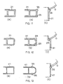
- This embodiment is characteristic in that it is provided with shoulders 25 which work as stop means to prevent the tube from being inserted too deeply into the header, 13, 14. More specifically, the tube 11 includes a body 111 and a head 111a which has shoulders 25 therebetween. The shoulders 25 are adapted to come into abutment with the heaters 13, 14 when the tube 11 is inserted into the slit15.
- Fig. 11 shows the process of forming stop means 125.
- the tube 211 has sharp or acute corners. The corners are cut away in such a manner as to form bulged portions 125, which provide stop means.
- Fig. 12 shows a tube 311 having round corners, which are split lengthwise in such a manner as to form shoulders 225.
- Fig. 13 shows a tube 411 having a relatively thin wall. In this case the cutting and splitting are jointly used in such a manner as to form shoulders 325.
- Fig. 14 shows an example of the condenser embodying the present invention, characterized in that the condenser is provided with a space 27 void of any tube or fin so that an obstacle 26 is avoided when it is installed in an engine room or somewhere.
- This embodiment has a pair of headers 113 and 14, and the left-hand header 113 is divided into two parts 113a and 113b.
- the tubes 11 consist of longer tubes 11a and shorter tubes 11b, which are connected to the header 113b at their left-hand ends. The other ends thereof are connected to the header 14.
- the outlet pipe 18 is provided on the header 113b.
- the coolant introduced through the inlet pipe 16 flows in the direction of arrows up to the right-hand header 14, and makes a U-turn to flow through the shorter tubes 11b up to the header 113b, where it is let out through the outlet pipe 18.
- the number of the space 27 is determined in accordance with that of an obstacle 26; when three spaces are to be given, three kinds of lengths of tubes are used.
Abstract
Description
- The present invention relates to a condenser for use as a cooler in automobiles and more particularly to a condenser for such use, which is preferably made of aluminum. Herein "aluminum" includes aluminum alloys.
- In general heat exchangers as car coolers use a high pressure gaseous coolant, and they must have an anti-pressure construction.
- To this end the known heat exchangers are provided with a core which includes flat tubes arranged in zigzag forms, each tube having pores and fins interposed between one tube and the next. Hereinafter this type of heat exchanger will be referred to as a serpentine type heat exchanger.
- The serpentine type heat exchangers are disadvantageous in that the coolant undergoes a relatively large resistance while flowing throughout the tubes. To reduce the resistance the common practice is to use wider tubes so as to increase the cross-sectional area thereof. However this leads to a large core and on the other hand an accommodation space in the automobile is very much limited. As a result this practice is not always effective.
- Another practice is to placing more fins by reducing the distances between the tubes. This requires that the height of each fin is reduced. However, when the fins are too small the bending work becomes difficult, and takes more time and labour.
- In general the condenser has a coolant path which consists of two sections, that is, an inlet section, hereinafter referred to as "condensing section" in which the coolant is still gaseous and an outlet section, hereinafter referred to as "supercooling section" in which it becomes liquid. In order to increase the heat exchange efficiency it is essential to increase the area for effecting heat transfer in the condensing section, whereas it is no problem for the supercooling section to have a reduced area for heat transfer.
- The conventional serpentine type heat exchangers have a coolant passageway which consists of a single tube. It is impossible for a single tube to be large in some parts and small in others. If the tube is to have a wider cross-sectional section the tube per se must be large throughout the entire length; in other words a large tube must be used. This of course leads to a larger condenser.
- As is evident from the foregoing description it is difficult to improve the conventional serpentine type heat exchangers merely by changing the dimensional factors thereof.
- Basically the serpentine type heat exchangers involve the complicated process which consists of bending tubes and then assembling them into a core in combination with fins. This is why it is difficult to produce the heat exchangers on automatic mass production line. Non-automatic production is costly.
- The present invention aims at solving the difficulties pointed out with respect to the conventional serpentine type heat exchangers and has for its object to provide a condenser having a relatively small core which nevertheless includes a large effective cross-sectional area for coolant passageways, thereby reducing a possible resistance to the flow of coolant.
- According to the present invention a condenser for use in a car cooling system comprises a pair of parallel headers, a plurality of tubular elements whose opposite ends are connected to the headers and fins provided in the air paths between adjacent tubes, is characterized in that each header is cylindrical in shape, each tubular element is formed of a flattened hollow tube and the opposite end of the tubular elements are inserted into slits provided in the headers and soldered so as to be liquid-tight.
- As is evident from the summary of the invention, the present invention adopts a multi-flow pattern system, whereby the coolant flows through a plurality of tubular elements at one time. The effective cross-sectional area for coolant passageways can be increased merely by increasing the number of tubular elements, thereby reducing resistance acting on the coolant. This leads to the reduction in the pressure loss of coolant.
- In general, the multi-flow pattern system is difficult to withstand a high pressure provided by a pressurized gaseous coolant because of the relatively fragile joints between the headers and tubular elements and the headers per se which are constructed without presupposing the high pressure which would act thereon by the coolant. In order to solve this problem encountered by the multi-flow pattern system the condenser of the present invention uses a cylindrical pipe for the header, and flat tubes for the tubular elements, whose opposite ends are inserted in the slits produced in the headers and soldered therein thereby ensuring that the condenser withstands a high pressure provided by the coolant.
- Each of the headers is internally divided by a partition into at least two sections; that is, a condensing section and a supercooling section, wherein the condensing section has a coolant in it gaseous state whereas the supercooling section has a coolant in its liquid state. When the coolant is in a gaseous state its volume is large, which requires a relatively large effective cross-sectional area for the coolant passageways. When it is in a liquid state the volume reduces, thereby allowing the coolant passageway to have a relatively small cross-sectional area.
- In this condenser the dimensional relationships among the width, height and pitch of the tubular elements and fins are as follows:
Width of the tubular element: 6 to 12mm
Height of the tubular element: 5mm or less
Height of each fin: 8 to 16mm
Fin Pitch: 1.6 to 3.2mm - The tubular elements are jointed to the headers; more specifically, the opposite ends of each tubular element are inserted into slits produced in the headers so that they fit therein in a liquid-tight manner and then they are soldered therein. Prior to the insertion the tubular elements or the headers or both are provided with a layer of a soldering substance. All the soldering is effected at one time by placing the assembled unit in a furnace, thereby saving time and labour in the assembling work.
- The invention will now be described further, by way of example, with reference to the accompanying drawings, in which:-
- Fig. 1 is a front view showing a condenser embodying the present invention;
- Fig. 2 is a plan view showing the condenser of Fig. 1;
- Fig. 3 is a perspective view showing the joint between the header and the individual tubes;
- Fig. 4 is a cross-sectional view through the line 4-4 in Fig. 1;
- Fig. 5 is a cross-sectional view showing the joint between the header and the tube;
- Fig. 6 is a cross-sectional view of the tube exemplifying a dimensional relationship about it;
- Fig. 7 is a cross-sectional view of the fin exemplifying a dimensional relationship about it;
- Fig. 8 is an explanatory view showing a flow pattern of coolant;
- Fig. 9 is a perspective view showing a modified version of the joint between the tubes and the header;
- Fig. 10 is a cross-sectional view showing the relationship between the tube and the header after they are jointed to each other;
- Fig. 11 is a cross-sectional view showing a modified version of the stopper produced in the tube;
- Fig. 12 is a cross-sectional view showing another modified version of the stopper;
- Fig. 13 is a cross-sectional view showing a further modified version of the stopper;
- Fig. 14 is a front view showing a modified version of the condenser;
- Fig. 15 is a graph showing the relationship between the width of the tubes and the rate of air passage therethrough;
- Fig. 16 is a graph showing the relationship between the height of the tubes and the pressure loss of air; and
- Fig. 17 is a graph showing variations in the heat exchange efficiency with respect to the height of the fins and the pressure loss of air.
- As shown in Fig. 1 the
condenser 10 of the present invention includes a plurality ofplanar tubes 11, andcorrugated fins 12 alternately arranged. Thetubes 11 are connected toheaders - The
tube 11 is planar, made of aluminum; preferably, of a multi-hollow type. - The
header slits 15 produced at equal intervals along its length, where the ends of thetubes 11 are soldered to therespective headers hand header 13 is provided with acoolant inlet pipe 16 at its upper end and aplug 17 at the lower end. The right-hand header 14 is provided with acoolant outlet pipe 18 at its lower end and aplug 19 at its upper end. The coolant inlet and outlet are diametrically located. The reference numerals 23 and 24 denote side plates fixed to thefins 12 located at the outermost positions. - Each
header partition partition 20 in theheader 13 is located slightly toward theinlet 16, whereas thepartition 21 in theheader 14 is located about 1/3 the length toward theoutlet 18. - Because of the provision of the
partitions headers - Referring to Fig. 8 the coolant introduced into the core through the
inlet pipe 16 flows to the right-hand header 14 in the inlet section (A), and then in a reversed direction in the middle section (B). In the outlet section (C) the flow of coolant is again reversed and led to the right-hand header 14, where it is discharged through theoutlet pipe 18. While the coolant is flowing through the sections (A), (B) and (C) heat exchange takes place between the coolant and the air passing through thefins 12. In the inlet section (A) the coolant is in its gaseous stage, but because of the large effective cross-sectional area in the section (A) heat exchange proceeds efficiently between the coolant and the air. In the section (C) the coolant is in its liquid state, and reduced in its volume, which allows the section (C) to have a relatively small cross-sectional area for coolant passageway as compared with the section (B). In this way the coolant passes through the first condensing section (A), the second section (B) and the third supercooling section (C), in the course of which heat exchange smoothly and efficiently takes places. - In the illustrated embodiment the numbers of tubes are progressively decreased from the section (A) to the section (B) and to the section (C). However, it is possible to give the same number of tubes to the sections (A) and (B), and a smaller number of tubes to the section (C). Alternatively it is possible to arrange so that each section (A) to (C) has the same number of tubes but their cross-sectional areas are progressively reduced from the section (A) to the section (B) and to the section (C). As a further modification the intermediate section (B) can be omitted; in this case the flow pattern is called a two-path system. In contrast, the above-mentioned embodiment is called a three-path system. As a still further modification one or more intermediate sections can be added.
- The illustrated embodiment has the headers located at the left-hand side and the right-hand side but they can be located at the upper side and the lower side wherein the tubes and fins are vertically arranged.
- To joint the
tubes 11 to theheaders aluminum pipe 13a, such as a clad metal pipe, which is used as theheaders clad pipe 13a has a layer of asoldering substance 13b. Thepipe 13 b is electrically seamed but can be made by extrusion or any other known method. For the soldering substance an Al·Si alloy preferably containing 6 to 13% by weight of Si is used. Thetubes 11 are inserted in theslits 15 for their end portions to be held therein. Then they are heated together to melt the soldering substance. In this case, as clearly shown in Fig. 5 the ajoining parts of thetube 11 and theclad pipe 13a havefillets 29, whereby theheader tubes 11 are jointed to each other without gaps interposed therebetween. Likewise, thecorrugated fins 12 can be provided with a layer of a soldering substance, thereby effecting the soldering joint between thefins 12 and thetubes 11 simultaneously when thetubes 11 are jointed to theheaders headers tubes 11 and thefins 12, thereby saving labour and time in the assembling work. The layer of a soldering substance can be provided in the inner surface of theclad pipe 13a but the place is not limited to it. - The
partitions respective headers - The
clad pipe 13a is previously provided with asemi-circular slit 28 in its wall, wherein theslit 28 covers half the circumference of thepipe 13a. Thepartition circular portion 20a and a large circular-portion 20b, wherein the smallercircular portion 20a has a diameter equal to the inside diameter of thepipe 13a, and wherein the largercircular portion 20b has a diameter equal to the outside diameter of thepipe 13a. Thelarger diameter portion 20b is inserted and soldered in theslit 28. Theheaders partitions tubes 11 are soldered to the headers, 13, 14. This finishes the soldering joint among the headers, the tubes, the fins and the partitions at one time. Thelarger diameter portion 20b fits in theslit 28 so that no leakage of coolant is likely to occur, and that the appearance of an outer surface of thepipe 13a is maintained. In addition, thelarger diameter portion 20b is embedded in theslit 28, thereby preventing thepartition - As is generally known in the art, a possible pressure loss of air largely depends on the relative positional relationship between the
tubes 11 and thefins 12. A reduced pressure loss leads to the increased heat exchange efficiency. Accordingly, the heat exchange efficiency depends on this positional relationship between them. Now, referring to Figs. 7 and 8 this positional relationship will be described. - It is prescribed so that the
tube 11 has a width (W) of 6 to 12mm, and a height (Ht) of not smaller than 5mm, and that thefin 12 has a height (Hf) of 8 to 16mm, and a fin patch (Fp) of 1.6 to 3.2mm. Referring to Figs. 15, 16 and 17 the reasons for the prescriptions are as follows: - As shown in Fig. 15, if the
tube 11 has a width of smaller than 6mm thefin 12 will be accordingly narrower, thereby reducing the number oflouvers 12a. The reduced number oflouvers 12a leads to less efficient heat exchange. If the tube is wide enough to allow an adequate number oflouvers 12a to be provided on thefins 12, the heat exchange efficiency will be enhanced. However if the width (W) of the tube is more than 12mm, thefins 12 will be accordingly widened, thereby increasing its weight. In addition too wide fins and too many louvers are likely to increase resistance to the air passing therethrough, thereby causing a greater pressure loss or air. - If the
fins 12 have a height (Hf) of more than 5mm the pressure loss of air will increase. The inside height (Hp) of thetubes 11 is preferably not smaller than 8mm. The inside height (Hp) is important in that it defines the size of an effective coolant passageway. If it is smaller than 8mm the pressure loss of coolant will increase, thereby reducing the heat exchange efficiency. In order to maintain a height (Hp) of at least 1.8mm for coolant passageway, the height (Ht) of thetube 11 will have to be at least 2.5mm, inclusive of the thickness of the tube wall. - As shown in Fig. 17, if the height (Hf) of the
fin 12 is not larger than 8mm the pressure loss of air will increase, but if it is larger than 16mm the number of fins will have to be redued, thereby reducing the heat exchange efficiency. - If the pitch (Fp) of
fins 12 is smaller than 1.6mm there will occur an interference between theadjacent louvers 12a, thereby amplifying the pressure loss of air. However if it exceeds 3.2mm the heat exchange efficiency will decrease. - Referring to Figs. 9 and 10 a modified version will be described:
- This embodiment is characteristic in that it is provided with
shoulders 25 which work as stop means to prevent the tube from being inserted too deeply into the header, 13, 14. More specifically, thetube 11 includes abody 111 and ahead 111a which hasshoulders 25 therebetween. Theshoulders 25 are adapted to come into abutment with theheaters tube 11 is inserted into the slit15. - As modified versions of the stop means various examples are shown in Figs. 11 to 13:
- Fig. 11 shows the process of forming stop means 125. In (a) the
tube 211 has sharp or acute corners. The corners are cut away in such a manner as to form bulgedportions 125, which provide stop means. Fig. 12 shows atube 311 having round corners, which are split lengthwise in such a manner as to formshoulders 225. Fig. 13 shows atube 411 having a relatively thin wall. In this case the cutting and splitting are jointly used in such a manner as to formshoulders 325. - Fig. 14 shows an example of the condenser embodying the present invention, characterized in that the condenser is provided with a
space 27 void of any tube or fin so that anobstacle 26 is avoided when it is installed in an engine room or somewhere. This embodiment has a pair ofheaders hand header 113 is divided into twoparts tubes 11 consist oflonger tubes 11a andshorter tubes 11b, which are connected to theheader 113b at their left-hand ends. The other ends thereof are connected to theheader 14. Theoutlet pipe 18 is provided on theheader 113b. The coolant introduced through theinlet pipe 16 flows in the direction of arrows up to the right-hand header 14, and makes a U-turn to flow through theshorter tubes 11b up to theheader 113b, where it is let out through theoutlet pipe 18. The number of thespace 27 is determined in accordance with that of anobstacle 26; when three spaces are to be given, three kinds of lengths of tubes are used.
Claims (14)
Width of the tubular element: 6 to 12mm
Height of the tubular element: 5mm or less
Height of the fin: 8 to 16mm
Pitch of the fins: 1.6 to 3.2mm
Priority Applications (4)
| Application Number | Priority Date | Filing Date | Title |
|---|---|---|---|
| AT87306599T ATE58009T1 (en) | 1986-07-29 | 1987-07-27 | CONDENSER. |
| EP89202415A EP0360362B1 (en) | 1986-07-29 | 1987-07-27 | Condenser |
| EP92200033A EP0479775B1 (en) | 1986-07-29 | 1987-07-27 | Condenser |
| EP19920200034 EP0480914A3 (en) | 1986-07-29 | 1987-07-27 | Condenser |
Applications Claiming Priority (4)
| Application Number | Priority Date | Filing Date | Title |
|---|---|---|---|
| JP179763/86 | 1986-07-29 | ||
| JP17976386A JPS6334466A (en) | 1986-07-29 | 1986-07-29 | Condenser |
| JP263138/86 | 1986-11-04 | ||
| JP26313886 | 1986-11-04 |
Related Child Applications (1)
| Application Number | Title | Priority Date | Filing Date |
|---|---|---|---|
| EP89202415.9 Division-Into | 1987-07-27 |
Publications (3)
| Publication Number | Publication Date |
|---|---|
| EP0255313A2 true EP0255313A2 (en) | 1988-02-03 |
| EP0255313A3 EP0255313A3 (en) | 1989-08-09 |
| EP0255313B1 EP0255313B1 (en) | 1990-10-31 |
Family
ID=26499512
Family Applications (4)
| Application Number | Title | Priority Date | Filing Date |
|---|---|---|---|
| EP19920200034 Ceased EP0480914A3 (en) | 1986-07-29 | 1987-07-27 | Condenser |
| EP92200033A Expired - Lifetime EP0479775B1 (en) | 1986-07-29 | 1987-07-27 | Condenser |
| EP89202415A Revoked EP0360362B1 (en) | 1986-07-29 | 1987-07-27 | Condenser |
| EP87306599A Revoked EP0255313B1 (en) | 1986-07-29 | 1987-07-27 | Condenser |
Family Applications Before (3)
| Application Number | Title | Priority Date | Filing Date |
|---|---|---|---|
| EP19920200034 Ceased EP0480914A3 (en) | 1986-07-29 | 1987-07-27 | Condenser |
| EP92200033A Expired - Lifetime EP0479775B1 (en) | 1986-07-29 | 1987-07-27 | Condenser |
| EP89202415A Revoked EP0360362B1 (en) | 1986-07-29 | 1987-07-27 | Condenser |
Country Status (5)
| Country | Link |
|---|---|
| US (2) | US5025855B1 (en) |
| EP (4) | EP0480914A3 (en) |
| AT (1) | ATE197501T1 (en) |
| CA (1) | CA1301161C (en) |
| DE (3) | DE3765875D1 (en) |
Cited By (32)
| Publication number | Priority date | Publication date | Assignee | Title |
|---|---|---|---|---|
| EP0341347A1 (en) * | 1988-05-11 | 1989-11-15 | Waagner-Biro Aktiengesellschaft | Apparatus for the indirect heating of a fluidised bed |
| EP0351938A2 (en) * | 1988-07-14 | 1990-01-24 | Showa Aluminum Kabushiki Kaisha | An aluminum heat exchanger |
| EP0359358A1 (en) * | 1988-09-14 | 1990-03-21 | Showa Aluminum Kabushiki Kaisha | A condenser |
| EP0374896A2 (en) * | 1988-12-22 | 1990-06-27 | THERMAL-WERKE Wärme-, Kälte-, Klimatechnik GmbH | Flat tube condenser, manufacturing method and uses |
| EP0374895A2 (en) * | 1988-12-22 | 1990-06-27 | THERMAL-WERKE Wärme-, Kälte-, Klimatechnik GmbH | Refrigerant condenser for a vehicle air conditioning unit |
| DE3843306A1 (en) * | 1988-12-22 | 1990-06-28 | Thermal Waerme Kaelte Klima | Flat pipe liquefier for a coolant of an air-conditioning system for a vehicle |
| EP0377936A1 (en) * | 1988-12-27 | 1990-07-18 | Modine Manufacturing Company | Heat exchanger |
| EP0379701A1 (en) * | 1989-01-12 | 1990-08-01 | Behr GmbH & Co. | Heat exchanger |
| US4972683A (en) * | 1989-09-01 | 1990-11-27 | Blackstone Corporation | Condenser with receiver/subcooler |
| EP0453738A1 (en) * | 1990-04-21 | 1991-10-30 | Behr GmbH & Co. | Heat-exchanger |
| DE4020591A1 (en) * | 1990-06-28 | 1992-01-02 | Diesel Kiki Co | Heat exchanger for vehicles - has alternating flat tubes and corrugated ribs of defined sizes |
| DE4020592A1 (en) * | 1990-03-13 | 1992-01-02 | Diesel Kiki Co | DIRECT CURRENT TYPE HEAT EXCHANGER FOR VEHICLES |
| AU637807B2 (en) * | 1989-08-23 | 1993-06-10 | Showa Denko Kabushiki Kaisha | Duplex heat exchanger |
| US5251692A (en) * | 1991-06-20 | 1993-10-12 | Thermal-Werke Warme-, Kalte-, Klimatechnik Gmbh | Flat tube heat exchanger, method of making the same and flat tubes for the heat exchanger |
| US5297624A (en) * | 1991-07-02 | 1994-03-29 | Thermal-Werke Warme-, Kalte-, Klimatechnik Gmbh | Header for a flat tube liquefier |
| GB2272506A (en) * | 1992-11-02 | 1994-05-18 | Nippon Denso Co | Refrigerant condenser |
| US5458190A (en) * | 1986-07-29 | 1995-10-17 | Showa Aluminum Corporation | Condenser |
| US5482112A (en) * | 1986-07-29 | 1996-01-09 | Showa Aluminum Kabushiki Kaisha | Condenser |
| USRE35655E (en) * | 1986-07-29 | 1997-11-11 | Showa Aluminum Corporation | Condenser for use in a car cooling system |
| USRE35711E (en) * | 1986-07-29 | 1998-01-06 | Showa Aluminum Corporation | Condenser for use in a car cooling system |
| USRE35742E (en) * | 1986-07-29 | 1998-03-17 | Showa Aluminum Corporation | Condenser for use in a car cooling system |
| EP0840082A1 (en) * | 1996-11-04 | 1998-05-06 | Valeo Thermique Moteur S.A. | Condensor with simplified assembly, for vehicle air-conditioning system |
| DE19825867A1 (en) * | 1997-06-17 | 1998-12-24 | Valeo Thermique Moteur Sa | Heat exchanger for charge air for an internal combustion engine |
| FR2766913A1 (en) * | 1997-07-30 | 1999-02-05 | Valeo Thermique Moteur Sa | TUBING OF A COLLECTOR BOX, ESPECIALLY OF A HEAT EXCHANGER OF A VENTILATION, HEATING AND / OR AIR-CONDITIONING SYSTEM OF A MOTOR VEHICLE, AND METHOD FOR FIXING THIS TUBING |
| DE19957945A1 (en) * | 1999-12-02 | 2001-06-07 | Behr Gmbh & Co | Condenser for refrigerant circuit in vehicle air-conditioning unit, has collection pipes at ends of horizontal pipes divided to form multiflow, with hot gas, condensation and lower cooling areas |
| GB2384848A (en) * | 2002-01-31 | 2003-08-06 | Visteon Global Tech Inc | A condenser for a refrigeration system |
| DE202008009812U1 (en) | 2008-07-21 | 2008-11-06 | Behr Gmbh & Co. Kg | capacitor |
| WO2008125089A3 (en) * | 2007-04-12 | 2009-04-30 | Automotivethermotech Gmbh | High-capacity heat exchanger for motor vehicles, and heater/air conditioner comprising a high-capacity heat exchanger |
| EP2865980A1 (en) * | 2013-07-16 | 2015-04-29 | Samsung Electronics Co., Ltd | Heat exchanger |
| EP3312542A1 (en) * | 2016-10-24 | 2018-04-25 | Hamilton Sundstrand Corporation | Heat exchanger with integral bleed air ejector |
| WO2019211108A1 (en) * | 2018-04-30 | 2019-11-07 | Valeo Termico, S.A. | Heat exchanger for gases, especially engine exhaust gases |
| CN113587495A (en) * | 2020-04-30 | 2021-11-02 | 杭州三花微通道换热器有限公司 | Air conditioning unit with multiple refrigeration systems |
Families Citing this family (44)
| Publication number | Priority date | Publication date | Assignee | Title |
|---|---|---|---|---|
| JPH0729416Y2 (en) * | 1990-04-05 | 1995-07-05 | 株式会社ゼクセル | Heat exchanger tank partitioning device |
| JP3013492B2 (en) * | 1990-10-04 | 2000-02-28 | 株式会社デンソー | Refrigeration apparatus, heat exchanger with modulator, and modulator for refrigeration apparatus |
| USRE36408E (en) * | 1990-10-04 | 1999-11-30 | Nippondenso Co., Ltd. | Refrigerating apparatus and modulator |
| US5224358A (en) * | 1990-10-04 | 1993-07-06 | Nippondenso Co., Ltd. | Refrigerating apparatus and modulator |
| DE9102265U1 (en) * | 1991-02-26 | 1991-05-16 | Zehnder-Beutler Gmbh, 7630 Lahr, De | |
| JP2541409B2 (en) * | 1991-11-15 | 1996-10-09 | 日本電装株式会社 | Heat exchanger |
| DE4212070A1 (en) * | 1992-04-10 | 1993-10-14 | Laengerer & Reich Gmbh & Co | Heat exchangers, especially coolers, e.g. B. oil cooler |
| FR2690235A1 (en) * | 1992-04-16 | 1993-10-22 | Valeo Thermique Moteur Sa | Tubular box wall of fluid and method for the manufacture of a heat exchanger by driving of circulation tubes. |
| DE4213509A1 (en) * | 1992-04-24 | 1993-10-28 | Audi Ag | Heat exchanger for condenser of vehicle air conditioning system - has parallel pairs of U=shaped tubes joined to tubular casing divided into inlet and outlet chambers |
| US5209292A (en) * | 1992-05-15 | 1993-05-11 | Zexel Usa Corporation | Condenser header and tank assembly with interference fit baffle |
| GB2268255B (en) * | 1992-06-20 | 1995-08-30 | Gen Motors Corp | U-flow evaporators for vehicle air-conditioning systems |
| US5329995A (en) * | 1992-08-28 | 1994-07-19 | Valeo Engine Cooling Incorporated | Heat exchanger assembly I |
| JPH0684188U (en) * | 1993-04-26 | 1994-12-02 | サンデン株式会社 | Heat exchanger |
| US5329988A (en) * | 1993-05-28 | 1994-07-19 | The Allen Group, Inc. | Heat exchanger |
| JP3044440B2 (en) * | 1993-10-22 | 2000-05-22 | 株式会社ゼクセル | Stacked evaporator |
| CA2215172C (en) * | 1997-09-11 | 2005-11-29 | Sean Terence Brooks | Baffle insert for heat exchangers |
| RO120359B1 (en) | 1998-06-12 | 2005-12-30 | S.C. Romradiatoare S.A. | Heat exchanger radiating element and process for making such a heat exchanger |
| TW487797B (en) * | 1998-07-31 | 2002-05-21 | Sanden Corp | Heat exchanger |
| DE19915389A1 (en) * | 1999-04-06 | 2000-10-12 | Behr Gmbh & Co | Multi-block heat exchanger |
| JP4560902B2 (en) * | 2000-06-27 | 2010-10-13 | 株式会社デンソー | Heat exchanger and manufacturing method thereof |
| IT1318751B1 (en) * | 2000-08-09 | 2003-09-10 | Kea S R L | HEATING DEVICE |
| DE60100617T2 (en) | 2000-10-06 | 2004-06-09 | Visteon Global Technologies, Inc., Dearborn | Manufacture of a tube for a heat exchanger |
| CA2323026A1 (en) | 2000-10-10 | 2002-04-10 | Long Manufacturing Ltd. | Heat exchangers with flow distributing orifice partitions |
| US6964296B2 (en) * | 2001-02-07 | 2005-11-15 | Modine Manufacturing Company | Heat exchanger |
| JP4153178B2 (en) * | 2001-06-26 | 2008-09-17 | カルソニックカンセイ株式会社 | Heat exchanger tank and manufacturing method thereof |
| US20030094260A1 (en) * | 2001-11-19 | 2003-05-22 | Whitlow Gregory Alan | Heat exchanger tube with stone protection appendage |
| CA2381214C (en) | 2002-04-10 | 2007-06-26 | Long Manufacturing Ltd. | Heat exchanger inlet tube with flow distributing turbulizer |
| KR100463540B1 (en) * | 2002-12-09 | 2004-12-29 | 엘지전자 주식회사 | structure for condenser in condensing type clothes dryer |
| KR20040080830A (en) * | 2003-03-13 | 2004-09-20 | 엘지전자 주식회사 | Heat exchanger and manufacturing method thereof |
| CA2454283A1 (en) * | 2003-12-29 | 2005-06-29 | Anis Muhammad | Insert molded structure and method for the manufacture thereof |
| US6988538B2 (en) | 2004-01-22 | 2006-01-24 | Hussmann Corporation | Microchannel condenser assembly |
| US7540431B2 (en) * | 2004-11-24 | 2009-06-02 | Dana Canada Corporation | By-pass valve for heat exchanger |
| US20060130517A1 (en) * | 2004-12-22 | 2006-06-22 | Hussmann Corporation | Microchannnel evaporator assembly |
| DE102005017252A1 (en) | 2005-04-14 | 2006-10-19 | Modine Manufacturing Co., Racine | Arrangement of heat exchangers in the motor vehicle |
| WO2008092677A1 (en) * | 2007-01-31 | 2008-08-07 | Behr Gmbh & Co. Kg | Heat exchanger |
| DE102007051128A1 (en) | 2007-10-24 | 2009-04-30 | Behr Gmbh & Co. Kg | Heat exchanger i.e. cooling agent condenser, for air conditioning system of motor vehicle, has collecting pipe fastened to connecting flanges that comprise set of retaining ribs, respectively |
| US20090173478A1 (en) * | 2008-01-09 | 2009-07-09 | Delphi Technologies, Inc. | Frost tolerant fins |
| DE102011007216A1 (en) | 2011-04-12 | 2012-10-18 | Behr Gmbh & Co. Kg | Refrigerant condenser assembly |
| DE102011080673B4 (en) | 2011-08-09 | 2024-01-11 | Mahle International Gmbh | Refrigerant condenser assembly |
| DE102014219387A1 (en) | 2014-09-25 | 2016-03-31 | Mahle International Gmbh | Collector and associated heat exchanger |
| KR102400223B1 (en) * | 2017-12-21 | 2022-05-23 | 한온시스템 주식회사 | Heat exchanger |
| DE102018202652A1 (en) | 2018-02-22 | 2019-08-22 | Volkswagen Aktiengesellschaft | Heat exchanger tube and heat exchanger with at least one such heat exchanger tube |
| CN108954922A (en) * | 2018-08-28 | 2018-12-07 | 珠海格力电器股份有限公司 | A kind of micro-channel heat exchanger and air conditioner |
| JPWO2021070312A1 (en) * | 2019-10-10 | 2021-04-15 |
Citations (14)
| Publication number | Priority date | Publication date | Assignee | Title |
|---|---|---|---|---|
| US1958226A (en) * | 1932-04-06 | 1934-05-08 | Fedders Mfg Co Inc | Condenser for refrigerating apparatus |
| FR1431920A (en) * | 1965-02-06 | 1966-03-18 | Ferodo Sa | Improvements to heat exchangers |
| US3307622A (en) * | 1964-12-30 | 1967-03-07 | Borg Warner | Round tank heat exchanger |
| US3524500A (en) * | 1968-07-02 | 1970-08-18 | Carlos Benjumeda | Heat transmission system |
| FR2287963A1 (en) * | 1974-10-15 | 1976-05-14 | Chausson Usines Sa | Brazing aluminium alloy heat-exchanger parts - using vitreous enamel coating to eliminate need for special protective brazing atmos |
| DE2603968A1 (en) * | 1976-02-03 | 1977-08-04 | Bbc Brown Boveri & Cie | Motor vehicle air conditioner refrigerator regulator - supplies bled refrigerant vapour to compressor at constant pressure preventing overheating |
| FR2367996A1 (en) * | 1976-10-16 | 1978-05-12 | Sueddeutsche Kuehler Behr | Vehicle air conditioning system condenser - has long and short tube sets connected in series form L-shaped assembly |
| FR2390694A1 (en) * | 1977-05-12 | 1978-12-08 | Modine Mfg Co | WELDED HEAT EXCHANGER |
| EP0002687A1 (en) * | 1977-12-24 | 1979-07-11 | Küppersbusch Aktiengesellschaft | Apparatus using heat exchange |
| JPS58221393A (en) * | 1982-06-18 | 1983-12-23 | Hitachi Ltd | Corrugate type heat exchanger |
| WO1984001208A1 (en) * | 1982-09-24 | 1984-03-29 | Bryce H Knowlton | Improved radiator assembly |
| EP0138435A2 (en) * | 1983-10-19 | 1985-04-24 | General Motors Corporation | Tube and fin heat exchanger |
| GB2167850A (en) * | 1984-12-04 | 1986-06-04 | Sanden Corp | Aluminum heat exchanger |
| EP0219974B1 (en) * | 1985-10-02 | 1996-11-06 | Modine Manufacturing Company | Condenser with small hydraulic diameter flow path |
Family Cites Families (61)
| Publication number | Priority date | Publication date | Assignee | Title |
|---|---|---|---|---|
| US131779A (en) * | 1872-10-01 | Improvement in steam-condensers | ||
| US1078271A (en) * | 1912-11-27 | 1913-11-11 | California Corrugated Culvert Company | Slide-gate. |
| US2004390A (en) * | 1934-04-11 | 1935-06-11 | Griscom Russell Co | Heat exchanger |
| US2200788A (en) * | 1939-02-18 | 1940-05-14 | Joseph A Coy | Heat exchanger and absorber |
| US2573161A (en) * | 1947-12-12 | 1951-10-30 | Trane Co | Heat exchanger |
| US2824720A (en) * | 1955-06-15 | 1958-02-25 | Allan N Johannesen | Condenser for refrigeration systems |
| US3310869A (en) * | 1963-11-27 | 1967-03-28 | Fedders Corp | Method of making radiators |
| FR2094566A5 (en) * | 1970-06-25 | 1972-02-04 | Chausson Usines Sa | |
| US3689972A (en) * | 1970-11-19 | 1972-09-12 | Modine Mfg Co | Method of fabricating a heat exchanger |
| US3675710A (en) * | 1971-03-08 | 1972-07-11 | Roderick E Ristow | High efficiency vapor condenser and method |
| IT969325B (en) * | 1971-08-06 | 1974-03-30 | Chausson Usines Sa | PROCEDURE FOR THE BRAZING OF ALUMINUM AND RADIATORS RE OBTAINED |
| BE787265A (en) * | 1971-08-09 | 1972-12-01 | Chausson Usines Sa | HEAT EXCHANGER, ESPECIALLY FOR HEATING VEHICLES |
| US3759321A (en) * | 1971-10-22 | 1973-09-18 | Singer Co | Condenser coil apparatus |
| JPS4849054A (en) * | 1971-10-22 | 1973-07-11 | ||
| JPS48100746A (en) * | 1972-04-04 | 1973-12-19 | ||
| US3860038A (en) * | 1973-01-08 | 1975-01-14 | Burton Gerald V | Test coupling |
| JPS49114145A (en) * | 1973-03-09 | 1974-10-31 | ||
| JPS548344B2 (en) * | 1974-02-14 | 1979-04-14 | ||
| US4141409A (en) * | 1977-04-21 | 1979-02-27 | Karmazin Products Corporation | Condenser header construction |
| US4207662A (en) * | 1977-06-22 | 1980-06-17 | Nihon Radiator Co., Ltd. | Method of manufacturing an aluminum heat exchanger |
| GB1601954A (en) * | 1978-05-15 | 1981-11-04 | Covrad Ltd | Heat exchanger |
| JPS5510072A (en) * | 1978-07-08 | 1980-01-24 | Citizen Watch Co Ltd | Metered liquid feeding apparatus |
| US4202407A (en) * | 1978-07-24 | 1980-05-13 | Didier Engineering Gmbh | Apparatus for cooling gases from coke plants |
| US4201263A (en) * | 1978-09-19 | 1980-05-06 | Anderson James H | Refrigerant evaporator |
| JPS5572795A (en) * | 1978-11-21 | 1980-05-31 | Nippon Denso Co Ltd | Corrugated fin type heat exchanger |
| US4209059A (en) * | 1978-12-11 | 1980-06-24 | Swiss Aluminium Ltd. | Crevice-corrosion resistant aluminum radiator triclad composite |
| JPS5853711B2 (en) * | 1979-01-29 | 1983-11-30 | 株式会社日本製鋼所 | Nickel-chromium-molybdenum-based high strength, high toughness thick wall steel for pressure vessels |
| CH640631A5 (en) * | 1979-06-20 | 1984-01-13 | Bbc Brown Boveri & Cie | HEAT EXCHANGER. |
| US4391027A (en) * | 1979-12-17 | 1983-07-05 | Ex-Cell-O Corporation | Method of making a heat exchanger assembly |
| DE3005751A1 (en) * | 1980-02-15 | 1981-08-20 | Küba Kühlerfabrik Baierbrunn H.W.Schmitz GmbH & Co KG, 8021 Baierbrunn | METHOD AND DEVICE FOR INCREASING THE HEATING OUTPUT OF EVAPORATORS |
| US4354240A (en) * | 1980-03-24 | 1982-10-12 | Sperry Corporation | Flight path transition control apparatus with predictive roll command |
| JPS56155391A (en) * | 1980-04-30 | 1981-12-01 | Nippon Denso Co Ltd | Corrugated fin type heat exchanger |
| JPS5738169U (en) * | 1980-08-14 | 1982-03-01 | ||
| JPS6054877B2 (en) * | 1980-08-18 | 1985-12-02 | 松下電器産業株式会社 | Magnetofluidic recording device |
| JPS5766389A (en) * | 1980-10-09 | 1982-04-22 | Tokyo Shibaura Electric Co | Device for monitoring withdrawal of nuclear control rod |
| JPS5787576A (en) * | 1980-11-21 | 1982-06-01 | Hitachi Ltd | Heat exchanger |
| GB2090652A (en) * | 1981-01-02 | 1982-07-14 | British Aluminium The Co Ltd | Improvements Relating to Heat Exchangers |
| JPS57142493A (en) * | 1981-02-27 | 1982-09-03 | Nippon Denso Co Ltd | Aluminum heat exchanger |
| JPS5874102A (en) * | 1981-10-29 | 1983-05-04 | Agency Of Ind Science & Technol | Condenser |
| JPS58221390A (en) * | 1982-06-18 | 1983-12-23 | Nippon Denso Co Ltd | Heat exchanger |
| JPS5919880A (en) * | 1982-07-26 | 1984-02-01 | Nec Corp | Clock device |
| US4516630A (en) * | 1982-07-27 | 1985-05-14 | Honda Giken Kogyo Kabushiki Kaisha | Motorcycle radiator |
| JPS5937564A (en) * | 1982-08-27 | 1984-03-01 | Canon Inc | Transfer material conveying device |
| US4615952A (en) * | 1982-10-29 | 1986-10-07 | Norsk Hydro A.S. | Aluminum shapes coated with brazing material and process of coating |
| JPS59140123A (en) * | 1983-01-28 | 1984-08-11 | Honda Motor Co Ltd | Radiator device for motor-cycle |
| JPS59173693A (en) * | 1983-03-21 | 1984-10-01 | Nippon Denso Co Ltd | Heat exchanger |
| JPS59181997A (en) * | 1983-03-31 | 1984-10-16 | Yonezawa Seisakusho:Kk | Deciding method of acceleration and deceleration of motor |
| JPS6015064A (en) * | 1983-07-06 | 1985-01-25 | Hitachi Ltd | Heat exchanger |
| JPS6091977A (en) * | 1983-10-25 | 1985-05-23 | Matsunaga Makoto | Apparatus for automatic feeding of test paper |
| JPS60191858A (en) * | 1984-03-12 | 1985-09-30 | Rizumu Jidosha Buhin Seizo Kk | Braking fluid pressure control unit |
| DE3423746A1 (en) * | 1984-06-28 | 1986-01-09 | Thermal-Werke Wärme-Kälte-Klimatechnik GmbH, 6832 Hockenheim | Heat exchanger laminar for tubes with an elliptical or oval cross-section |
| US4712612A (en) * | 1984-10-12 | 1987-12-15 | Showa Aluminum Kabushiki Kaisha | Horizontal stack type evaporator |
| JPS6193387A (en) * | 1984-10-12 | 1986-05-12 | Showa Alum Corp | Heat exchanger |
| JPS61114094A (en) * | 1984-11-06 | 1986-05-31 | Matsushita Electric Ind Co Ltd | Heat exchanger |
| GB2167699B (en) * | 1984-12-04 | 1988-04-27 | Sanden Corp | A method for producing a heat exchanger |
| JPS61179763A (en) * | 1985-02-05 | 1986-08-12 | Citizen Watch Co Ltd | Thermal transfer printer |
| JPS61263138A (en) * | 1985-05-16 | 1986-11-21 | Rohm Co Ltd | Manufacture of semiconductor device |
| US4998580A (en) * | 1985-10-02 | 1991-03-12 | Modine Manufacturing Company | Condenser with small hydraulic diameter flow path |
| US4688311A (en) * | 1986-03-03 | 1987-08-25 | Modine Manufacturing Company | Method of making a heat exchanger |
| DE3765875D1 (en) * | 1986-07-29 | 1990-12-06 | Showa Aluminium Co Ltd | CONDENSER. |
| US4825941B1 (en) * | 1986-07-29 | 1997-07-01 | Showa Aluminum Corp | Condenser for use in a car cooling system |
-
1987
- 1987-07-27 DE DE8787306599T patent/DE3765875D1/en not_active Revoked
- 1987-07-27 AT AT92200033T patent/ATE197501T1/en not_active IP Right Cessation
- 1987-07-27 EP EP19920200034 patent/EP0480914A3/en not_active Ceased
- 1987-07-27 DE DE8989202415T patent/DE3780648T2/en not_active Revoked
- 1987-07-27 EP EP92200033A patent/EP0479775B1/en not_active Expired - Lifetime
- 1987-07-27 EP EP89202415A patent/EP0360362B1/en not_active Revoked
- 1987-07-27 DE DE3752324T patent/DE3752324T2/en not_active Expired - Lifetime
- 1987-07-27 EP EP87306599A patent/EP0255313B1/en not_active Revoked
- 1987-07-28 CA CA000543185A patent/CA1301161C/en not_active Expired - Lifetime
-
1990
- 1990-04-16 US US07509901 patent/US5025855B1/en not_active Ceased
-
1995
- 1995-07-21 US US08/505,494 patent/USRE35655E/en not_active Expired - Lifetime
Patent Citations (14)
| Publication number | Priority date | Publication date | Assignee | Title |
|---|---|---|---|---|
| US1958226A (en) * | 1932-04-06 | 1934-05-08 | Fedders Mfg Co Inc | Condenser for refrigerating apparatus |
| US3307622A (en) * | 1964-12-30 | 1967-03-07 | Borg Warner | Round tank heat exchanger |
| FR1431920A (en) * | 1965-02-06 | 1966-03-18 | Ferodo Sa | Improvements to heat exchangers |
| US3524500A (en) * | 1968-07-02 | 1970-08-18 | Carlos Benjumeda | Heat transmission system |
| FR2287963A1 (en) * | 1974-10-15 | 1976-05-14 | Chausson Usines Sa | Brazing aluminium alloy heat-exchanger parts - using vitreous enamel coating to eliminate need for special protective brazing atmos |
| DE2603968A1 (en) * | 1976-02-03 | 1977-08-04 | Bbc Brown Boveri & Cie | Motor vehicle air conditioner refrigerator regulator - supplies bled refrigerant vapour to compressor at constant pressure preventing overheating |
| FR2367996A1 (en) * | 1976-10-16 | 1978-05-12 | Sueddeutsche Kuehler Behr | Vehicle air conditioning system condenser - has long and short tube sets connected in series form L-shaped assembly |
| FR2390694A1 (en) * | 1977-05-12 | 1978-12-08 | Modine Mfg Co | WELDED HEAT EXCHANGER |
| EP0002687A1 (en) * | 1977-12-24 | 1979-07-11 | Küppersbusch Aktiengesellschaft | Apparatus using heat exchange |
| JPS58221393A (en) * | 1982-06-18 | 1983-12-23 | Hitachi Ltd | Corrugate type heat exchanger |
| WO1984001208A1 (en) * | 1982-09-24 | 1984-03-29 | Bryce H Knowlton | Improved radiator assembly |
| EP0138435A2 (en) * | 1983-10-19 | 1985-04-24 | General Motors Corporation | Tube and fin heat exchanger |
| GB2167850A (en) * | 1984-12-04 | 1986-06-04 | Sanden Corp | Aluminum heat exchanger |
| EP0219974B1 (en) * | 1985-10-02 | 1996-11-06 | Modine Manufacturing Company | Condenser with small hydraulic diameter flow path |
Non-Patent Citations (1)
| Title |
|---|
| PATENT ABSTRACTS OF JAPAN, vol. 8, no. 76 (M-288)[1513], 9th April 1984; & JP-A-58 221 393 (HITACHI SEISAKUSHO K.K.) 23-12-1983 * |
Cited By (49)
| Publication number | Priority date | Publication date | Assignee | Title |
|---|---|---|---|---|
| USRE35742E (en) * | 1986-07-29 | 1998-03-17 | Showa Aluminum Corporation | Condenser for use in a car cooling system |
| USRE35711E (en) * | 1986-07-29 | 1998-01-06 | Showa Aluminum Corporation | Condenser for use in a car cooling system |
| USRE35655E (en) * | 1986-07-29 | 1997-11-11 | Showa Aluminum Corporation | Condenser for use in a car cooling system |
| US5482112A (en) * | 1986-07-29 | 1996-01-09 | Showa Aluminum Kabushiki Kaisha | Condenser |
| US5458190A (en) * | 1986-07-29 | 1995-10-17 | Showa Aluminum Corporation | Condenser |
| EP0341347A1 (en) * | 1988-05-11 | 1989-11-15 | Waagner-Biro Aktiengesellschaft | Apparatus for the indirect heating of a fluidised bed |
| EP0351938A2 (en) * | 1988-07-14 | 1990-01-24 | Showa Aluminum Kabushiki Kaisha | An aluminum heat exchanger |
| EP0351938A3 (en) * | 1988-07-14 | 1990-04-18 | Showa Aluminum Kabushiki Kaisha | An aluminum heat exchanger |
| EP0359358A1 (en) * | 1988-09-14 | 1990-03-21 | Showa Aluminum Kabushiki Kaisha | A condenser |
| EP0448183A3 (en) * | 1988-09-14 | 1991-10-16 | Showa Aluminum Kabushiki Kaisha | A condenser |
| DE3918312A1 (en) * | 1988-12-22 | 1990-12-06 | Thermal Waerme Kaelte Klima | FLAT TUBE CONDENSER, MANUFACTURING PROCESS AND APPLICATION |
| EP0374896A3 (en) * | 1988-12-22 | 1990-10-24 | THERMAL-WERKE Wärme-, Kälte-, Klimatechnik GmbH | Flat tube condenser, manufacturing method and uses |
| EP0374896A2 (en) * | 1988-12-22 | 1990-06-27 | THERMAL-WERKE Wärme-, Kälte-, Klimatechnik GmbH | Flat tube condenser, manufacturing method and uses |
| EP0374895A2 (en) * | 1988-12-22 | 1990-06-27 | THERMAL-WERKE Wärme-, Kälte-, Klimatechnik GmbH | Refrigerant condenser for a vehicle air conditioning unit |
| EP0374895A3 (en) * | 1988-12-22 | 1990-10-17 | THERMAL-WERKE Wärme-, Kälte-, Klimatechnik GmbH | Refrigerant condenser for a vehicle air conditioning unit |
| DE3843306A1 (en) * | 1988-12-22 | 1990-06-28 | Thermal Waerme Kaelte Klima | Flat pipe liquefier for a coolant of an air-conditioning system for a vehicle |
| EP0377936A1 (en) * | 1988-12-27 | 1990-07-18 | Modine Manufacturing Company | Heat exchanger |
| EP0379701A1 (en) * | 1989-01-12 | 1990-08-01 | Behr GmbH & Co. | Heat exchanger |
| AU637807B2 (en) * | 1989-08-23 | 1993-06-10 | Showa Denko Kabushiki Kaisha | Duplex heat exchanger |
| US4972683A (en) * | 1989-09-01 | 1990-11-27 | Blackstone Corporation | Condenser with receiver/subcooler |
| WO1991003692A1 (en) * | 1989-09-01 | 1991-03-21 | Blackstone Corporation | Condenser with receiver/subcooler |
| EP0415840A1 (en) * | 1989-09-01 | 1991-03-06 | Valeo Engine Cooling, Inc. | Condenser with receiver/subcooler |
| DE4020592A1 (en) * | 1990-03-13 | 1992-01-02 | Diesel Kiki Co | DIRECT CURRENT TYPE HEAT EXCHANGER FOR VEHICLES |
| EP0453738A1 (en) * | 1990-04-21 | 1991-10-30 | Behr GmbH & Co. | Heat-exchanger |
| DE4020591A1 (en) * | 1990-06-28 | 1992-01-02 | Diesel Kiki Co | Heat exchanger for vehicles - has alternating flat tubes and corrugated ribs of defined sizes |
| US5251692A (en) * | 1991-06-20 | 1993-10-12 | Thermal-Werke Warme-, Kalte-, Klimatechnik Gmbh | Flat tube heat exchanger, method of making the same and flat tubes for the heat exchanger |
| US5297624A (en) * | 1991-07-02 | 1994-03-29 | Thermal-Werke Warme-, Kalte-, Klimatechnik Gmbh | Header for a flat tube liquefier |
| GB2272506A (en) * | 1992-11-02 | 1994-05-18 | Nippon Denso Co | Refrigerant condenser |
| GB2272506B (en) * | 1992-11-02 | 1996-07-24 | Nippon Denso Co | Refrigerant condenser |
| EP0840082A1 (en) * | 1996-11-04 | 1998-05-06 | Valeo Thermique Moteur S.A. | Condensor with simplified assembly, for vehicle air-conditioning system |
| FR2755506A1 (en) * | 1996-11-04 | 1998-05-07 | Valeo Thermique Moteur Sa | SIMPLIFIED CONDENSER FOR VEHICLE AIR CONDITIONING CIRCUIT |
| US5894885A (en) * | 1996-11-04 | 1999-04-20 | Valeo Thermique Moteur | Condenser having a simplified assembly for use in an air conditioning circuit for a vehicle |
| DE19825867A1 (en) * | 1997-06-17 | 1998-12-24 | Valeo Thermique Moteur Sa | Heat exchanger for charge air for an internal combustion engine |
| FR2766913A1 (en) * | 1997-07-30 | 1999-02-05 | Valeo Thermique Moteur Sa | TUBING OF A COLLECTOR BOX, ESPECIALLY OF A HEAT EXCHANGER OF A VENTILATION, HEATING AND / OR AIR-CONDITIONING SYSTEM OF A MOTOR VEHICLE, AND METHOD FOR FIXING THIS TUBING |
| WO1999006783A1 (en) * | 1997-07-30 | 1999-02-11 | Valeo Thermique Moteur | Heat exchanger manifold connection piece and method for fixing same |
| US6231088B1 (en) | 1997-07-30 | 2001-05-15 | Valeo Thermique Moteur | Heat exchanger header box connector and method of fixing same |
| DE19957945B4 (en) * | 1999-12-02 | 2005-07-21 | Behr Gmbh & Co. Kg | Condenser with subcooling line |
| DE19957945A1 (en) * | 1999-12-02 | 2001-06-07 | Behr Gmbh & Co | Condenser for refrigerant circuit in vehicle air-conditioning unit, has collection pipes at ends of horizontal pipes divided to form multiflow, with hot gas, condensation and lower cooling areas |
| GB2384848A (en) * | 2002-01-31 | 2003-08-06 | Visteon Global Tech Inc | A condenser for a refrigeration system |
| WO2008125089A3 (en) * | 2007-04-12 | 2009-04-30 | Automotivethermotech Gmbh | High-capacity heat exchanger for motor vehicles, and heater/air conditioner comprising a high-capacity heat exchanger |
| EP2140219A2 (en) | 2007-04-12 | 2010-01-06 | AutomotiveThermoTech GmbH | High-capacity heat exchanger for motor vehicles, and heater/air conditioner comprising a high-capacity heat exchanger |
| CN101675313B (en) * | 2007-04-12 | 2012-02-15 | 汽车热技术有限公司 | High-capacity heat exchanger for motor vehicles, and heater/air conditioner comprising a high-capacity heat exchanger |
| DE202008009812U1 (en) | 2008-07-21 | 2008-11-06 | Behr Gmbh & Co. Kg | capacitor |
| EP2865980A1 (en) * | 2013-07-16 | 2015-04-29 | Samsung Electronics Co., Ltd | Heat exchanger |
| EP3312542A1 (en) * | 2016-10-24 | 2018-04-25 | Hamilton Sundstrand Corporation | Heat exchanger with integral bleed air ejector |
| US10203159B2 (en) | 2016-10-24 | 2019-02-12 | Hamilton Sundstrand Corporation | Heat exchanger with integral bleed air ejector |
| WO2019211108A1 (en) * | 2018-04-30 | 2019-11-07 | Valeo Termico, S.A. | Heat exchanger for gases, especially engine exhaust gases |
| CN113587495A (en) * | 2020-04-30 | 2021-11-02 | 杭州三花微通道换热器有限公司 | Air conditioning unit with multiple refrigeration systems |
| CN113587495B (en) * | 2020-04-30 | 2023-02-28 | 杭州三花微通道换热器有限公司 | Air conditioning unit with multiple refrigeration systems |
Also Published As
| Publication number | Publication date |
|---|---|
| EP0480914A2 (en) | 1992-04-15 |
| DE3780648D1 (en) | 1992-08-27 |
| DE3752324D1 (en) | 2000-12-14 |
| EP0480914A3 (en) | 1992-05-13 |
| EP0360362B1 (en) | 1992-07-22 |
| US5025855A (en) | 1991-06-25 |
| EP0255313A3 (en) | 1989-08-09 |
| DE3765875D1 (en) | 1990-12-06 |
| EP0479775B1 (en) | 2000-11-08 |
| ATE197501T1 (en) | 2000-11-11 |
| US5025855B1 (en) | 1996-09-24 |
| USRE35655E (en) | 1997-11-11 |
| EP0360362A1 (en) | 1990-03-28 |
| EP0479775A3 (en) | 1992-05-06 |
| CA1301161C (en) | 1992-05-19 |
| EP0255313B1 (en) | 1990-10-31 |
| DE3752324T2 (en) | 2001-03-29 |
| DE3780648T2 (en) | 1992-12-17 |
| EP0479775A2 (en) | 1992-04-08 |
Similar Documents
| Publication | Publication Date | Title |
|---|---|---|
| EP0255313B1 (en) | Condenser | |
| US4825941A (en) | Condenser for use in a car cooling system | |
| US4936379A (en) | Condenser for use in a car cooling system | |
| US5372188A (en) | Heat exchanger for a refrigerant system | |
| EP1231448B1 (en) | Heat exchanger | |
| CA2023499C (en) | Duplex heat exchanger | |
| US5246064A (en) | Condenser for use in a car cooling system | |
| US5441106A (en) | Heat exchange tubes | |
| US5036911A (en) | Embossed plate oil cooler | |
| US5743328A (en) | Duplex heat exchanger | |
| US4688311A (en) | Method of making a heat exchanger | |
| US5190100A (en) | Condenser for use in a car cooling system | |
| EP0881449A2 (en) | Refrigerant tubes for heat exchangers | |
| JPH1114288A (en) | Heat exchanger | |
| JPH0345300B2 (en) | ||
| JPH05215482A (en) | Heat exchanger | |
| CA1324602C (en) | Condenser | |
| JPH0332944Y2 (en) | ||
| JPH0345301B2 (en) | ||
| JPH02302592A (en) | Heat exchanger | |
| JP2963222B2 (en) | Brazing joint structure of heat exchange medium inlet and outlet tubes in heat exchanger | |
| JPH033828Y2 (en) | ||
| JPH04288491A (en) | Metallic heat exchanger | |
| JPH11294991A (en) | Integrally juxtaposed heat exchanger | |
| KR0161440B1 (en) | Heat exchanger |
Legal Events
| Date | Code | Title | Description |
|---|---|---|---|
| PUAI | Public reference made under article 153(3) epc to a published international application that has entered the european phase |
Free format text: ORIGINAL CODE: 0009012 |
|
| AK | Designated contracting states |
Kind code of ref document: A2 Designated state(s): AT DE FR GB SE |
|
| PUAL | Search report despatched |
Free format text: ORIGINAL CODE: 0009013 |
|
| AK | Designated contracting states |
Kind code of ref document: A3 Designated state(s): AT DE FR GB SE |
|
| 17P | Request for examination filed |
Effective date: 19890928 |
|
| 17Q | First examination report despatched |
Effective date: 19891124 |
|
| GRAA | (expected) grant |
Free format text: ORIGINAL CODE: 0009210 |
|
| AK | Designated contracting states |
Kind code of ref document: B1 Designated state(s): AT DE FR GB SE |
|
| REF | Corresponds to: |
Ref document number: 58009 Country of ref document: AT Date of ref document: 19901115 Kind code of ref document: T |
|
| XX | Miscellaneous (additional remarks) |
Free format text: TEILANMELDUNG 89202415.9 EINGEREICHT AM 25/09/89. |
|
| REF | Corresponds to: |
Ref document number: 3765875 Country of ref document: DE Date of ref document: 19901206 |
|
| ET | Fr: translation filed | ||
| PLBI | Opposition filed |
Free format text: ORIGINAL CODE: 0009260 |
|
| PLBI | Opposition filed |
Free format text: ORIGINAL CODE: 0009260 |
|
| PLBI | Opposition filed |
Free format text: ORIGINAL CODE: 0009260 |
|
| PLBI | Opposition filed |
Free format text: ORIGINAL CODE: 0009260 |
|
| 26 | Opposition filed |
Opponent name: KUEHLERFABRIK LAENGERER & REICH GMBH & CO. KG Effective date: 19910706 |
|
| 26 | Opposition filed |
Opponent name: BEHR GMBH & CO. Effective date: 19910712 Opponent name: KUEHLERFABRIK LAENGERER & REICH GMBH & CO. KG Effective date: 19910706 |
|
| 26 | Opposition filed |
Opponent name: ZEXEL CORPORATION Effective date: 19910726 Opponent name: VALEO THERMIQUE MOTEUR Effective date: 19910726 Opponent name: BEHR GMBH & CO. Effective date: 19910712 Opponent name: KUEHLERFABRIK LAENGERER & REICH GMBH & CO. KG Effective date: 19910706 |
|
| 26 | Opposition filed |
Opponent name: THERMAL-WERKE WAERME-, KAELTE-, KLIMATECHNIK Effective date: 19910731 Opponent name: ZEXEL CORPORATION Effective date: 19910726 Opponent name: VALEO THERMIQUE MOTEUR Effective date: 19910726 Opponent name: BEHR GMBH & CO. Effective date: 19910712 Opponent name: KUEHLERFABRIK LAENGERER & REICH GMBH & CO. KG Effective date: 19910706 |
|
| PLAB | Opposition data, opponent's data or that of the opponent's representative modified |
Free format text: ORIGINAL CODE: 0009299OPPO |
|
| R26 | Opposition filed (corrected) |
Opponent name: LAENGERER & REICH GMBH & CO. KG * 910712 BEHR GMB Effective date: 19910706 |
|
| EAL | Se: european patent in force in sweden |
Ref document number: 87306599.9 |
|
| PGFP | Annual fee paid to national office [announced via postgrant information from national office to epo] |
Ref country code: GB Payment date: 19960515 Year of fee payment: 10 |
|
| PGFP | Annual fee paid to national office [announced via postgrant information from national office to epo] |
Ref country code: FR Payment date: 19960528 Year of fee payment: 10 |
|
| PGFP | Annual fee paid to national office [announced via postgrant information from national office to epo] |
Ref country code: SE Payment date: 19960529 Year of fee payment: 10 |
|
| PGFP | Annual fee paid to national office [announced via postgrant information from national office to epo] |
Ref country code: AT Payment date: 19960618 Year of fee payment: 10 |
|
| PGFP | Annual fee paid to national office [announced via postgrant information from national office to epo] |
Ref country code: DE Payment date: 19960813 Year of fee payment: 10 |
|
| APAC | Appeal dossier modified |
Free format text: ORIGINAL CODE: EPIDOS NOAPO |
|
| RDAG | Patent revoked |
Free format text: ORIGINAL CODE: 0009271 |
|
| STAA | Information on the status of an ep patent application or granted ep patent |
Free format text: STATUS: PATENT REVOKED |
|
| GBPR | Gb: patent revoked under art. 102 of the ep convention designating the uk as contracting state |
Free format text: 960619 |
|
| 27W | Patent revoked |
Effective date: 19960619 |
|
| APAH | Appeal reference modified |
Free format text: ORIGINAL CODE: EPIDOSCREFNO |