EP0254942A2 - Positioning actuator - Google Patents
Positioning actuator Download PDFInfo
- Publication number
- EP0254942A2 EP0254942A2 EP87110077A EP87110077A EP0254942A2 EP 0254942 A2 EP0254942 A2 EP 0254942A2 EP 87110077 A EP87110077 A EP 87110077A EP 87110077 A EP87110077 A EP 87110077A EP 0254942 A2 EP0254942 A2 EP 0254942A2
- Authority
- EP
- European Patent Office
- Prior art keywords
- voltage
- input
- comparator
- signal
- output signal
- Prior art date
- Legal status (The legal status is an assumption and is not a legal conclusion. Google has not performed a legal analysis and makes no representation as to the accuracy of the status listed.)
- Granted
Links
Images
Classifications
-
- G—PHYSICS
- G05—CONTROLLING; REGULATING
- G05D—SYSTEMS FOR CONTROLLING OR REGULATING NON-ELECTRIC VARIABLES
- G05D3/00—Control of position or direction
- G05D3/12—Control of position or direction using feedback
- G05D3/14—Control of position or direction using feedback using an analogue comparing device
- G05D3/1472—Control of position or direction using feedback using an analogue comparing device with potentiometer
Definitions
- the present invention relates to an actuator according to the preamble of claims 1 and 2.
- valve cone of a valve with a special contour in order to specify a characteristic curve, in deviation from a linear characteristic curve, by means of which a flow rate that is not proportional to this is controlled as a function of an input variable.
- non-linear elements such as e.g. Diodes to specify a non-linear characteristic for the system deviation in the feedback branch.
- a characteristic curve is then established after the operational amplifier has been connected or after the valve cone has been machined.
- the present invention enables a separate setting of the limit values of the respective characteristic curve of the actuator and one Change in the shape of the characteristic.
- the characteristic curve can run progressively and degressively.
- the actuator according to the invention can be extremely easily and quickly adapted to the property of devices to be actuated by it, such as valves or the like, within wide limits, which can be done manually, for example, by appropriate settings of potentiometers within the circuit.
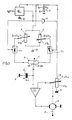
- FIG. 1 the circuit of an actuator is shown schematically, in which a comparator K1 compares a target value, which is formed here by the charging voltage u c1 of a capacitor D, with an actual value.
- the output signal of the comparator K1 controls as a control deviation a servomotor M, which forms the actuating device, for example for a valve, not shown, via a gear, not shown. This actuation is indicated by a dashed arrow P.
- the motor M also actuates the voltage tap (wiper) of a feedback potentiometer W, which is connected to the DC supply voltage U0 supplied by a DC voltage source 9.
- the voltage wU0 that can be tapped off at the voltage tap forms the actual value or the feedback voltage, which is fed to the comparator K1.
- the comparator output signal causes actuation of the motor M, the direction of rotation being the sign of the rule deviation is dependent. So there is practically a control of the angular position of the output shaft of the motor M shown here as an electric DC motor, the input variable u c1 forming a variable guide variable, which in turn is dependent on a DC input signal u e of the actuator.
- the motor M usually works via a gear on the actuator, for example the valve rod of a valve.
- the signal u e forms the input variable of the actuator and can be specified, for example, by a controller output.
- the setpoint u c1 is formed as a function of the direct voltage input signal u e in an electronic signal transmitter, which is described below.
- the likewise linear resistance R of a third potentiometer F can be connected to the wipers of the two potentiometers X, Y via a preferably electronic switch T1 and T2.
- the grinder position divides the resistance R on both sides of the grinder into the resistors zR and (1-z) R.
- the resistances of the two potentiometers X and Y should preferably be small compared to the resistance R of the potentiometer F, so that the capacitance C of the capacitor D together with the proportional resistance value zR or (1-z) R of the potentiometer F essentially determines the time constant ZRC or (1-z) RC for the respective charge change of the capacitor D.
- a voltage / pulse converter UI known per se is provided, which is also operated by the supply voltage U0 and to which the input variable u e is supplied, which can have values between 0 volts and U0, for example.
- the voltage / pulse converter UI converts the analog input variable u e into a square wave voltage, the pulse / pause ratio s of which corresponds is formed.
- This square-wave voltage appears at the output of the voltage / pulse converter UI and is supplied to the switch T1 directly and to the switch T2 via the inverter N as a control signal, so that whenever the switch T1 is switched on, the switch T2 is switched off and vice versa.
- the respective period of time during which the switch T1 is switched on and thus the switch T2 is blocked is denoted by ⁇ t 1 and the respective period of time during which the switch T1 is blocked and the switch T2 is switched on is denoted by ⁇ t 2.
- the wiper of the third potentiometer F is connected to the capacitor D already mentioned, whose other connection is at the negative pole of the supply voltage Uschreib, and to the setpoint input of the comparator K1.
- the circuit described above operates as follows, assuming that the negative pole B of the supply voltage is grounded.
- the maximum adjustment range of the motor M is covered if the input variable u e covers the entire supply voltage range U0 and if the voltage U0 can be picked up on the wiper of the potentiometer X or the voltage 0 (or vice versa) on the wiper of the potentiometer Y.
- the setting range can be set to different limit values, which correspond to the voltage values xU0 and yU0 that can be tapped at the grinders.
- the transfer function between the mentioned limit values of can be changed progressively via linear (grinder in middle position) to degressive, whereby the function can be increasing or decreasing, depending on whether xU0 is larger or smaller than yU0.
- This curve can thus be adjusted by means of the potentiometer F from progressively increasing or decreasing to linear to degressively increasing or decreasing and in the non-linear case has almost logarithmic characteristics in the circuit shown.
- the two switches T1 and T2 are alternately switched on and blocked via the square-wave voltage output by the voltage / pulse converter UI. As already mentioned above, the following applies:
- Equation 3 shows the requirements in the task ten properties for the start and end points of the capacitor voltage u c1 if the converter UI operates linearly, as is preferably provided:
- the two potentiometers X and Y can be used to set the start and end point for the voltage swing of u c1 and thus the desired limit values for the characteristic of this actuator.
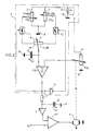
- the potentiometers X, Y and F forming the voltage dividers, the two switches T1 and T2, and the capacitor D are arranged in the same manner as described in FIG. 1 and can also be operated.
- the wipers of the potentiometer F and the feedback potentiometer W are connected to the inputs of a second comparator K2.
- This comparator K2 can be a Schmitt trigger, but possibly also another electronic switch with a small hysteresis.
- This switch K2 delivers a signal at its output, which in turn is a square wave signal with a pulse / The pause ratio s is which is fed directly to the control input of the switch T1 and to the control input of the switch T2 via an inverter N.
- the output signal of the comparator K2 is also fed to the comparator K1 as an actual value for smoothing via a low-pass filter, consisting of a resistor r and a further capacitor D ⁇ and via an isolation amplifier L. Also in this circuit, the resistances of the potentiometers X, Y are small against the resistance of the potentiometer F. During operation, the pulse / pause ratio s of the output signal of the comparator K2 is adjusted by the feedback potentiometer W.
- the voltage xU0 on the wiper of the potentiometer X is applied to the capacitor D via the resistor zR during the period ⁇ t1.
- the voltage yU0 is applied to the capacitor D through the resistor (1-z) R during the period .DELTA.t2.
- the capacitor D is therefore charged back and forth between the voltages xU0 and yU0 when the two switches T1 and T2 are correctly coupled within the hysteresis of the comparator K2.
- This voltage u c2 thus acts like the output voltage of a feedback potentiometer which can be varied within wide limits. It is conducted via the isolation amplifier L for comparison with the input voltage u e . The difference between u c2 - u e is then used to control the servomotor M and to reduce the respective control deviation, possibly down to zero.
- the circuit shown in FIG. 1 contains the voltage / pulse converter UI;
- the circuit part E framed in dash-dotted lines in FIG. 2 likewise forms a voltage / pulse converter, and this circuit part can thus also be used as a voltage / pulse converter UI in FIG. 1, the input variable u e of that being obtained via the wiper of the potentiometer W in FIG 2 corresponds to the voltage supplied and one can then provide two fixed resistors for the potentiometer F which are expediently of the same size.
- the switching ratio s of this voltage / pulse converter when used as a converter UI in FIG. 1, can expediently move from 0 to 1 when the input voltage runs from xU0 to yU0. This makes it possible to limit the input range as desired. This creates, inter alia, the possibility of providing several such actuators, if they have such converters, for sequence switching of actuators, since the transition from one actuator to the next actuator can then be set precisely by means of the potentiometers X and Y.
Landscapes
- Physics & Mathematics (AREA)
- General Physics & Mathematics (AREA)
- Engineering & Computer Science (AREA)
- Automation & Control Theory (AREA)
- Feedback Control In General (AREA)
- Control Of Position Or Direction (AREA)
- Vehicle Body Suspensions (AREA)
- Fluid-Damping Devices (AREA)
- Valve Device For Special Equipments (AREA)
Abstract
Description
Die vorliegende Erfindung betrifft einen Stellantrieb gemäß dem Gattungsbegriff der Patentansprüche 1 und 2.The present invention relates to an actuator according to the preamble of
Es ist bekannt, den Ventilkegel eines Ventils mit einer speziellen Kontur zu versehen, um - abweichend von einer linearen Kennlinie - eine Kennlinie vorzugeben, durch die in Abhängigkeit von einer Eingangsgröße eine hierzu nicht-proportionale Durchflußmenge gesteuert wird. Andererseits ist es bekannt, durch Beschaltung von die Regelabweichung bildenden Operationsverstärkern mit nicht-linearen Elementen, wie z.B. Dioden, im Rückführungszweig eine nicht-lineare Kennlinie für die Regelabweichung vorzugeben. Eine solche Kennlinie liegt aber dann nach Beschaltung des Operationsverstärkers bzw. nach einer Bearbeitung des Ventilkegels fest.It is known to provide the valve cone of a valve with a special contour in order to specify a characteristic curve, in deviation from a linear characteristic curve, by means of which a flow rate that is not proportional to this is controlled as a function of an input variable. On the other hand, it is known to connect non-linear elements, such as e.g. Diodes to specify a non-linear characteristic for the system deviation in the feedback branch. However, such a characteristic curve is then established after the operational amplifier has been connected or after the valve cone has been machined.
Es ist daher die Aufgabe der vorliegenden Erfindung, einen Stellantrieb anzugeben, bei welchem sowohl die Grenzwerte der Übertragungsfunktion (Kennlinie) des Stellantriebs einzeln wählbar sind als auch die Gestalt der Übertragungsfunktion in weiten Grenzen unterschiedlich wählbar ist, wobei dies kostengünstig schaltungstechnisch realisierbar sein soll.It is therefore the object of the present invention to specify an actuator in which both the limit values of the transfer function (characteristic curve) of the actuator can be selected individually and the shape of the transfer function can be selected within wide limits, which should be possible to implement at low cost in terms of circuitry.
Diese Aufgabe wird gelöst durch die kennzeichnenden Merkmale der unabhängigen Patentansprüche 1 und 2. Weitere vorteilhafte Ausgestaltungen des erfindungsgemäßen Stellantriebs sind den Unteransprüchen entnehmbar.This object is achieved by the characterizing features of
Die vorliegende Erfindung ermöglicht mit äußerst einfachen technischen Mitteln eine getrennte Einstellung der Grenzwerte der jeweiligen Kennlinie des Stellantriebes sowie eine Veränderung der Kennlinienform. Die Kennlinie kann hierbei progressiv und degressiv verlaufen.With extremely simple technical means, the present invention enables a separate setting of the limit values of the respective characteristic curve of the actuator and one Change in the shape of the characteristic. The characteristic curve can run progressively and degressively.
Der erfindungsgemäße Stellantrieb läßt sich an die Eigenschaft von durch ihn zu betätigenden Einrichtungen, wie Ventilen oder dergleichen, äußerst einfach und rasch in weiten Grenzen anpassen, was beispielsweise von Hand durch entsprechende Einstellungen von Potentiometern innerhalb der Schaltung vorgenommen werden kann.The actuator according to the invention can be extremely easily and quickly adapted to the property of devices to be actuated by it, such as valves or the like, within wide limits, which can be done manually, for example, by appropriate settings of potentiometers within the circuit.
Anhand von in den Figuren der beiliegenden Zeichnung dargestellten Ausführungsbeispielen sei die Erfindung im folgenden näher erläutert. Es zeigen:
- Fig. 1 die schematische Schaltung eines Stellantriebs mit einem Signalübertrager im Sollwertzweig des Stellungsreglers; und
- Fig. 2 die schematische Schaltung eines Stellantriebs mit einem Signalübertrager im Istwertzweig des Stellungsreglers.
- Figure 1 shows the schematic circuit of an actuator with a signal transmitter in the setpoint branch of the positioner. and
- Fig. 2 shows the schematic circuit of an actuator with a signal transmitter in the actual value branch of the positioner.
In Figur 1 ist schematisch die Schaltung eines Stellantriebs gezeigt, bei dem ein Komparator K1 einen Sollwert, der hier durch die Ladespannung uc1 eines Kondensators D gebildet wird, mit einem Istwert vergleicht. Das Ausgangssignal des Komparators K1 steuert als Regelabweichung einen Stellmotor M an, der über ein nicht dargestelltes Getriebe die Betätigungseinrichtung, z.B. für ein nicht dargestelltes Ventil, bildet. Diese Betätigung ist durch einen gestrichelten Pfeil P angedeutet.In Figure 1, the circuit of an actuator is shown schematically, in which a comparator K1 compares a target value, which is formed here by the charging voltage u c1 of a capacitor D, with an actual value. The output signal of the comparator K1 controls as a control deviation a servomotor M, which forms the actuating device, for example for a valve, not shown, via a gear, not shown. This actuation is indicated by a dashed arrow P.
Der Motor M betätigt auch den Spannungsabgriff (Schleifer) eines Rückführungspotentiometers W, welches an der von einer Gleichspannungsquelle 9 gelieferten Versorgungsgleichspannung U₀ liegt Die am Spannungsabgriff abgreifbare Spannung wU₀ bildet den Istwert bzw. die Rückführungsspannung, welche dem Komparator K1 zugeführt wird. Das Komparatorausgangssignal bewirkt eine Betätigung des Motors M, wobei die Drehrichtung von dem Vorzeichen der Regel abweichung abhängig ist. Es findet also praktisch eine Regelung der Winkelstellung der Ausgangswelle des hier als elektrischer Gleichstrommotor dargestellten Motors M statt, wobei die Eingangsgröße uc1 eine variable Führungs größe bildet, die ihrerseits abhängig ist von einem Gleichspannungs-Eingangssignal ue des Stellantriebes. Üblicherweise arbeitet der Motor M über ein Getriebe auf das Stellgleid, z.B. die Ventilstange eines Ventils. Das Signal ue bildet die Eingangsgröße des Stellantriebes und kann beispielsweise durch einen Reglerausgang vorgegeben sein.The motor M also actuates the voltage tap (wiper) of a feedback potentiometer W, which is connected to the DC supply voltage U₀ supplied by a DC voltage source 9. The voltage wU₀ that can be tapped off at the voltage tap forms the actual value or the feedback voltage, which is fed to the comparator K1. The comparator output signal causes actuation of the motor M, the direction of rotation being the sign of the rule deviation is dependent. So there is practically a control of the angular position of the output shaft of the motor M shown here as an electric DC motor, the input variable u c1 forming a variable guide variable, which in turn is dependent on a DC input signal u e of the actuator. The motor M usually works via a gear on the actuator, for example the valve rod of a valve. The signal u e forms the input variable of the actuator and can be specified, for example, by a controller output.
Der Sollwert uc1 wird in Abhängigkeit von dem Gleichspannungseingangssignal ue in einem elektronischen Signalübertrager gebildet, der nachstehend beschrieben wird.The setpoint u c1 is formed as a function of the direct voltage input signal u e in an electronic signal transmitter, which is described below.
Zwei parallel geschaltete lineare Potentiometer X und Y liegen zwischen den beiden Polen A und B der Versorgungsspannung U₀. Der ebenfalls lineare Widerstand R eines dritten Potentiometers F ist mit den Schleifern der beiden Potentiometer X, Y über je einen vorzugsweise elektronischen Schalter T1 und T2 verbindbar. Die Schleiferstellung teilt den Widerstand R zu beiden Seiten des Schleifers in die Widerstände zR und (1-z) R. Die Widerstände der beiden Potentiometer X und Y sollten bevorzugt klein gegen den Widerstand R des Potentiometers F sein, so daß die Kapazität C des Kondensators D zusammen mit dem anteiligen Widerstandswert zR bzw. (1-z)R des Potentiometers F im wesentlichen die Zeitkonstante ZRC bzw. (1-z)RC für die jeweilige Ladungsänderung des Kondensators D bestimmt.Two linear potentiometers X and Y connected in parallel lie between the two poles A and B of the supply voltage U₀. The likewise linear resistance R of a third potentiometer F can be connected to the wipers of the two potentiometers X, Y via a preferably electronic switch T1 and T2. The grinder position divides the resistance R on both sides of the grinder into the resistors zR and (1-z) R. The resistances of the two potentiometers X and Y should preferably be small compared to the resistance R of the potentiometer F, so that the capacitance C of the capacitor D together with the proportional resistance value zR or (1-z) R of the potentiometer F essentially determines the time constant ZRC or (1-z) RC for the respective charge change of the capacitor D.
Außerdem ist ein an sich bekannter Spannungs/Impuls-Wandler UI vorgesehen, der ebenfalls von der Versorgungsspannung U₀ betrieben wird und dem die Eingangsgröße ue zugeführt wird, welche beispielsweise Werte zwischen 0 Volt und U₀ aufweisen kann. Der Spannungs/Impuls-Wandler UI wandelt die analoge Eingangsgröße ue in eine Rechteckspannung um, deren Impuls/Pausenverhältnis s entsprechend
Diese Rechteckspannung erscheint am Ausgang des Spannungs/Impuls-Wandlers UI und wird dem Schalter T1 direkt und dem Schalter T2 über den Inverter N als Steuersignal zugeführt, so daß immer dann, wenn der Schalter T1 eingeschaltet ist, der Schalter T2 ausgeschaltet ist und umgekehrt. Die jeweilige Zeitspanne, während der der Schalter T1 eingeschaltet und damit der Schalter T2 gesperrt ist, ist mit Δt₁ und die jeweilige Zeitspanne, während der der Schalter T1 gesperrt und der Schalter T2 eingeschaltet ist, mit Δt₂ bezeichnet.This square-wave voltage appears at the output of the voltage / pulse converter UI and is supplied to the switch T1 directly and to the switch T2 via the inverter N as a control signal, so that whenever the switch T1 is switched on, the switch T2 is switched off and vice versa. The respective period of time during which the switch T1 is switched on and thus the switch T2 is blocked is denoted by
Der Schleifer des dritten Potentiometers F ist mit dem bereits genannten Kondensator D, dessen anderer Anschluß am Minuspol der Versorgungsspannung U₀ liegt, und mit dem Sollwerteingang des Komparators K1 verbunden.The wiper of the third potentiometer F is connected to the capacitor D already mentioned, whose other connection is at the negative pole of the supply voltage Uspannung, and to the setpoint input of the comparator K1.
Die vorstehend beschriebene Schaltung arbeitet folgendermaßen, wobei angenommen sei, daß der Minuspol B der Versorgungsspannung an Masse liegt.The circuit described above operates as follows, assuming that the negative pole B of the supply voltage is grounded.
Der maximale Stellbereich des Motors M wird überstrichen, wenn die Eingangsgröße ue den gesamten Versorgungsspannungsbereich U₀ überstreicht und wenn am Schleifer des Potentiometers X die Spannung U₀ bzw. am Schleiferdes Potentiometers Y die Spannung 0 (oder umgekehrt) abgreifbar ist. Durch Verändern dieser Schleiferstellungen kann der Stellbereich auf unterschiedliche Grenzwerte eingestellt werden, welche den an den Schleifern abgreifbaren Spannungswerten xU₀ und yU₀ entsprechen.The maximum adjustment range of the motor M is covered if the input variable u e covers the entire supply voltage range U₀ and if the voltage U₀ can be picked up on the wiper of the potentiometer X or the voltage 0 (or vice versa) on the wiper of the potentiometer Y. By changing these grinder positions, the setting range can be set to different limit values, which correspond to the voltage values xU₀ and yU₀ that can be tapped at the grinders.
Durch Veränderung der Schleiferstellung des Potentiometers F zwischen seinen beiden Endstellungen kann die Übertragungsfunktion zwischen den genannten Grenzwerten von progressiv über linear (Schleifer in Mittelstellung) bis degressiv verändert werden, wobei die Funktion steigend oder fallend verlaufen kann, je nachdem, ob xU₀ größer oder kleiner als yU₀ ist. Diese Übertragungsfunktion kann als Kennlinie oder Kurve h = f (ue) dargestellt werden, wobei h dem Drehwinkel und damit dem Stellweg des Motors M einschließlich Getriebe entspricht. Diese Kurve kann also mittels des Potentiometers F von progressiv steigend oder fallend über linear bis degressiv steigend oder fallend verstellt werden und hat im nicht-linearen Fall bei der dargestellten Schaltung nahezu logarithmische Charakteristik. Jedoch ist es auch möglich, diese Schaltung so abzuändern, daß sich auch andere nicht-lineare Kennlinien einstellen lassen, beispielsweise durch Ersatz des Kondensators D durch Kondesator-/Widerstandsketten.By changing the wiper position of the potentiometer F between its two end positions, the transfer function between the mentioned limit values of can be changed progressively via linear (grinder in middle position) to degressive, whereby the function can be increasing or decreasing, depending on whether xU₀ is larger or smaller than yU₀. This transfer function can be represented as a characteristic curve or curve h = f (u e ), where h corresponds to the angle of rotation and thus the actuating path of the motor M including the transmission. This curve can thus be adjusted by means of the potentiometer F from progressively increasing or decreasing to linear to degressively increasing or decreasing and in the non-linear case has almost logarithmic characteristics in the circuit shown. However, it is also possible to modify this circuit so that other non-linear characteristics can also be set, for example by replacing the capacitor D with capacitor / resistor chains.
Über die vom Spannungs/Impuls-Wandler UI ausgegebene Rechteckspannung werden abwechselnd die beiden Schalter T1 und T2 eingeschaltet und gesperrt. Es gilt wie oben bereits erwähnt:
Ferner gilt dann für die dargestellte Schaltung im stationären Schaltbetrieb (s = const), wenn also der Kondensator D ständig zwischen den Spannungen xU₀ und yU₀ umgeladen wird, bei linearer Näherung, die bei genügend geringer Hysterese noch gute Ergebnisse liefert:
Aus Gleichung 3 sind die in der Aufgabenstellung geforder ten Eigenschaften für die Anfangs- und Endpunkte der Kondensatorspannung uc1 zu entnehmen, wenn der Wandler UI linear arbeitet, wie bevorzugt vorgesehen ist:
Mit den beiden Potentiometern X und Y lassen sich also Anfangs- und Endpunkt für den Spannungshub von uc1 und damit die jeweils gewünschten Grenzwerte der Kennlinie dieses Stellantriebes einstellen.The two potentiometers X and Y can be used to set the start and end point for the voltage swing of u c1 and thus the desired limit values for the characteristic of this actuator.
Für z= 0,5 (Schleifer steht in Mittelstellung des Potentiometers F) sind die beiden Ladezeitkonstanten des Kondensators D gleich. Dann ergibt sich
ρ= sx + y · (1-s)
Wenn sich in diesem Fall also s von 0 bis 1 ändert, so bewegt sich uc1 zwischen yU₀ und xU₀ und die Kennlinie dieses Stellantriebes ist dann eine Gerade. Die Gerade steigt, wenn x > y ist, und sie fällt, wenn y > x ist.For z = 0.5 (slider is in the middle position of potentiometer F), the two charging time constants of capacitor D are the same. Then it turns out
ρ = sx + y · (1-s)
If in this case s changes from 0 to 1, u c1 moves between yU₀ and xU₀ and the characteristic of this actuator is then a straight line. The line rises when x> y and falls when y> x.
Das gleiche gilt auch für die Fälle, wo z ≠ 0,5 ist. Diese sollen nun noch näher untersucht werden.The same applies to cases where z z 0.5. These will now be examined in more detail.
Differenziert man Gleichung 3 nach s, so ergibt sich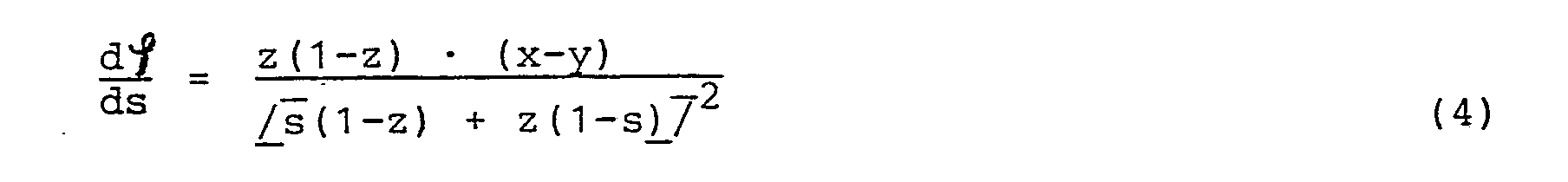


Aus beiden Gleichungen ergibt sich, daß der Differentialquotient für z = 0,5 am Anfang und Ende der Kennlinie den Betrag x - y hat. Aus Gleichung 3 ergibt sich direkt, daß dies auch über der gesamten s-Achse gilt.From both equations it follows that the differential quotient for z = 0.5 at the beginning and end of the characteristic curve has the amount x - y. From equation 3 it follows directly that this also applies over the entire s-axis.
Aus den Beziehungen für s = 0 und s = 1 ergibt sich nun für die die jeweilige Kennlinie dieses Stellgliedes bildende Kurve:
z < 0,5 : Kurvenanstieg am Anfang (s=0) steil, am Ende (s=1) flach
z > 0,5 : Kurvenanstieg am Anfang (s=0) flach, am Ende (s=1) steil.The relationships for s = 0 and s = 1 now result for the curve forming the respective characteristic of this actuator:
z <0.5: curve rise steep at the beginning (s = 0), flat at the end (s = 1)
z> 0.5: Curve rise flat at the beginning (s = 0), steep at the end (s = 1).
Die gewünschte logaritmische Charakteristik läßt sich über einen genügend großen Bereich erreichen. Bis s = 0,1 herunter ist die Abweichung vom logarithmischen Verlauf im interessierenden Bereich von z kleiner als 2%.The desired logarithmic characteristic can be achieved over a sufficiently large range. Down to s = 0.1, the deviation from the logarithmic curve in the region of interest of z is less than 2%.
In Figur 2 ist schematisch die Schaltung eines Stellantriebes gezeigt, bei dem der Komparator K1 den Sollwert, der hier mit der Eingangsgröße ue identisch ist, mit einem Istwert vergleicht, wobei in diesem Fall der Signalübertrager im Istwertzweig zwischen dem Schleifer des Rückführungspotentiometers W und dem Istwerteingang des Komparators K1 angeordnet ist.In Figure 2, the circuit of an actuator is shown schematically, in which the comparator K1 compares the setpoint, which is identical here with the input variable u e , with an actual value, in which case the signal transmitter in the actual value branch between the wiper of the feedback potentiometer W and the Actual value input of the comparator K1 is arranged.
Bei diesem Signalübertrager sind die Spannungsteiler bildenden Potentiometer X, Y und F, die beiden Schalter T1 und T2, sowie der Kondensator D in der gleichen Weise, wie in Fig. 1 beschrieben, angeordnet und ebenso zu bedienen. Die Schleifer des Potentiometers F und des Rückführungspotentiometers W sind jedoch hier mit den Eingängen eines zweiten Komparators K2 verbunden. Dieser Komparator K2 kann besonders zweckmäßig ein Schmitt-Trigger, aber ggf. auch ein anderer elektronischer Schalter mit kleiner Hysterese, sein. Dieser Schalter K2 liefert an seinem Ausgang ein Signal, das wieder ein Rechtecksignal mit einem Impuls/ Pausenverhältnis s ist, welches dem Steuereingang des Schalters T1 direkt und dem Steuereingang des Schalters T2 über einen Inverter N zugeführt wird. Das Ausgangssignal des Komparators K2 wird außerdem zur Glättung über ein Tiefpaßfilter, bestehend aus einem Widerstand r und einem weiteren Kondensator Dʹ sowie über einen Trennverstärker L dem Komparator K1 als Istwert zugeführt. Auch bei dieser Schaltung sind zweckmäßig die Widerstände der Potentiometer X, Y klein gegen den Widerstand des Potentiometers F. Im Betrieb wird durch das Rückführungspotentiometer W das Impuls/Pausenverhältnis s des Ausgangssignales des Komparators K2 verstellt.In this signal transmitter, the potentiometers X, Y and F forming the voltage dividers, the two switches T1 and T2, and the capacitor D are arranged in the same manner as described in FIG. 1 and can also be operated. However, the wipers of the potentiometer F and the feedback potentiometer W are connected to the inputs of a second comparator K2. This comparator K2 can be a Schmitt trigger, but possibly also another electronic switch with a small hysteresis. This switch K2 delivers a signal at its output, which in turn is a square wave signal with a pulse / The pause ratio s is which is fed directly to the control input of the switch T1 and to the control input of the switch T2 via an inverter N. The output signal of the comparator K2 is also fed to the comparator K1 as an actual value for smoothing via a low-pass filter, consisting of a resistor r and a further capacitor Dʹ and via an isolation amplifier L. Also in this circuit, the resistances of the potentiometers X, Y are small against the resistance of the potentiometer F. During operation, the pulse / pause ratio s of the output signal of the comparator K2 is adjusted by the feedback potentiometer W.
Die Spannung xU₀ am Schleifer des Potentiometers X wird während der Zeitspanne Δt₁ über den Widerstand zR an den Kondensator D angelegt. Andererseits wird während der Zeitspanne Δt₂ die Spannung yU₀ über den Widerstand (1-z)R an den Kondensator D angelegt. Der Kondensator D wird also bei richtiger Ankopplung der beiden Schalter T1 und T2 innerhalb der Hysterese des Komparators K2 zwischen den Spannungen xU₀ und yU₀ hin und her geladen. Für diese Ladevorgänge gilt nun unter der Voraussetzung genügend kleiner Hysterese des Komparators K2 mit guter Näherung:


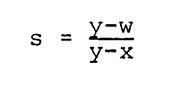
Die letzte Gleichung läßt auch wieder erkennen, daß die Kennlinie des Stellantriebs invertiert werden kann. Ist y > x, so fällt die Kennlinie, ist y < x, so steigt sie. Diese letzten Betrachtungen gelten auch für den allgemeinen Fall nach Gleichung 5.The last equation also shows that the characteristic of the actuator can be inverted. If y> x, the characteristic curve falls; if y <x, it increases. These last considerations also apply to the general case according to equation 5.
Durch Differentiation von Gleichung 5 nach w erhält man:
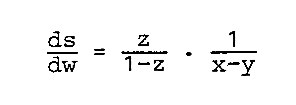
Für w = x folgt:
Aus den beiden letzten Gleichungen ist weiterhin wieder zu erkennen, daß bei x = y der Übergang von einer fallenden auf eine steigende Kennlinie stattfindet.It can also be seen from the last two equations that the transition from a falling to an increasing characteristic curve takes place at x = y.
Am Kondensator Dʹ liegt nun, wie sich leicht zeigen läßt, eine Spannung an, die sich mit guter Näherung aus der folgenden Beziehung ergibt: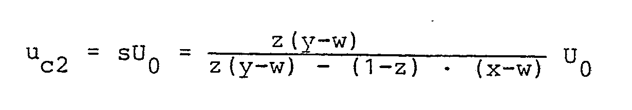
Die in Fig. 1 dargestellte Schaltung enthält den Spannungs/Impuls-Wandler UI; der in Figur 2 strichpunktiert eingerahmte Schaltungsteil E bildet ebenfalls einen Spannungs/Impuls-Wandler und dieser Schaltungsteil kann somit auch als Spannungs/Impuls-Wandler UI in Figur 1 eingesetzt werden, wobei die Eingangsgröße ue der ihr über den Schleifer des Potentiometers W in Fig. 2 zugeführten Spannung entspricht und man kann dann für das Potentiometer F zwei Festwiderstände vorsehen, die zweckmäßig gleich groß sind. Das Schaltverhältnis s dieses Spannungs/Impuls-Wandlers kann, wenn er in Figur 1 als Wandler UI eingesetzt wird, sich zweckmäßig von 0 nach 1 bewegen, wenn die Eingangsspannung von xU₀ nach yU₀ läuft. Damit wird also eine beliebig einstellbare Begrenzung des Eingangsbereiches möglich. Dies schafft u.a. die Möglichkeit, mehrere solche Stellantriebe, wenn sie solche Wandler aufweisen, für Sequenzschaltungen von Stellmotoren vorzusehen, da man dann den Übergang von dem einen Stellmotor auf den nächsten Stellmotor mittels der Potentiometer X und Y genau einstellen kann.The circuit shown in FIG. 1 contains the voltage / pulse converter UI; The circuit part E framed in dash-dotted lines in FIG. 2 likewise forms a voltage / pulse converter, and this circuit part can thus also be used as a voltage / pulse converter UI in FIG. 1, the input variable u e of that being obtained via the wiper of the potentiometer W in FIG 2 corresponds to the voltage supplied and one can then provide two fixed resistors for the potentiometer F which are expediently of the same size. The switching ratio s of this voltage / pulse converter, when used as a converter UI in FIG. 1, can expediently move from 0 to 1 when the input voltage runs from xU₀ to yU₀. This makes it possible to limit the input range as desired. This creates, inter alia, the possibility of providing several such actuators, if they have such converters, for sequence switching of actuators, since the transition from one actuator to the next actuator can then be set precisely by means of the potentiometers X and Y.
Der Komparator K2 arbeitet also als Gleichspannungs/Impuls-wandler. Mit seinem Schaltverhältnis s wird der Kondensator Dʹ aufgeladen bzw. entladen und es ergibt sich
uc2 = sU₀
Die Nichtlinearität wird bei der Schaltung nach Fig. 2 direkt am Rückkopplungszweig eingeführt. Der Gleichspannungs/Impulswandler K2 ergibt im Rückkopplungszweig dann ein lineares Schaltverhältnis, wenn z = 0,5 ist, also wenn der Schleifer des Potentiometers F in der Mitte steht.The comparator K2 thus works as a DC voltage / pulse converter. With its switching ratio s, the capacitor Dʹ is charged or discharged and it results
u c2 = sU₀
In the circuit according to FIG. 2, the non-linearity is introduced directly at the feedback branch. The DC voltage / pulse converter K2 results in a linear switching ratio in the feedback branch when z = 0.5, that is, when the wiper of the potentiometer F is in the middle.
Claims (7)
Priority Applications (1)
| Application Number | Priority Date | Filing Date | Title |
|---|---|---|---|
| AT87110077T ATE75331T1 (en) | 1986-07-15 | 1987-07-13 | ACTUATOR. |
Applications Claiming Priority (2)
| Application Number | Priority Date | Filing Date | Title |
|---|---|---|---|
| DE3623780A DE3623780A1 (en) | 1986-07-15 | 1986-07-15 | ACTUATOR |
| DE3623780 | 1986-07-15 |
Publications (3)
| Publication Number | Publication Date |
|---|---|
| EP0254942A2 true EP0254942A2 (en) | 1988-02-03 |
| EP0254942A3 EP0254942A3 (en) | 1989-08-09 |
| EP0254942B1 EP0254942B1 (en) | 1992-04-22 |
Family
ID=6305180
Family Applications (1)
| Application Number | Title | Priority Date | Filing Date |
|---|---|---|---|
| EP87110077A Expired - Lifetime EP0254942B1 (en) | 1986-07-15 | 1987-07-13 | Positioning actuator |
Country Status (3)
| Country | Link |
|---|---|
| EP (1) | EP0254942B1 (en) |
| AT (1) | ATE75331T1 (en) |
| DE (2) | DE3623780A1 (en) |
Cited By (1)
| Publication number | Priority date | Publication date | Assignee | Title |
|---|---|---|---|---|
| US5157956A (en) * | 1988-07-25 | 1992-10-27 | Nissan Motor Company, Limited | Method of calibrating a throttle angle sensor |
Families Citing this family (2)
| Publication number | Priority date | Publication date | Assignee | Title |
|---|---|---|---|---|
| DE3807731A1 (en) * | 1988-03-09 | 1989-09-21 | Hella Kg Hueck & Co | Device for the regulation or control of the position of an actuator, especially an actuator for the control of the temperature of the interior or the headlamp range of motor vehicles |
| DE4431376C1 (en) * | 1994-08-29 | 1995-12-21 | Mannesmann Ag | Positional control circuit |
Citations (3)
| Publication number | Priority date | Publication date | Assignee | Title |
|---|---|---|---|---|
| DE1538391A1 (en) * | 1965-04-01 | 1969-06-19 | Cochran And Company Annan Ltd | Control circuit for a servomotor controllable by a relay |
| US4070610A (en) * | 1976-01-19 | 1978-01-24 | Johnson Controls, Inc. | Proportional motor circuit |
| GB2152243A (en) * | 1983-12-29 | 1985-07-31 | Alps Electric Co Ltd | Control circuit for motor actuator |
-
1986
- 1986-07-15 DE DE3623780A patent/DE3623780A1/en not_active Withdrawn
-
1987
- 1987-07-13 DE DE8787110077T patent/DE3778443D1/en not_active Expired - Lifetime
- 1987-07-13 AT AT87110077T patent/ATE75331T1/en not_active IP Right Cessation
- 1987-07-13 EP EP87110077A patent/EP0254942B1/en not_active Expired - Lifetime
Patent Citations (3)
| Publication number | Priority date | Publication date | Assignee | Title |
|---|---|---|---|---|
| DE1538391A1 (en) * | 1965-04-01 | 1969-06-19 | Cochran And Company Annan Ltd | Control circuit for a servomotor controllable by a relay |
| US4070610A (en) * | 1976-01-19 | 1978-01-24 | Johnson Controls, Inc. | Proportional motor circuit |
| GB2152243A (en) * | 1983-12-29 | 1985-07-31 | Alps Electric Co Ltd | Control circuit for motor actuator |
Cited By (1)
| Publication number | Priority date | Publication date | Assignee | Title |
|---|---|---|---|---|
| US5157956A (en) * | 1988-07-25 | 1992-10-27 | Nissan Motor Company, Limited | Method of calibrating a throttle angle sensor |
Also Published As
| Publication number | Publication date |
|---|---|
| EP0254942B1 (en) | 1992-04-22 |
| ATE75331T1 (en) | 1992-05-15 |
| DE3778443D1 (en) | 1992-05-27 |
| EP0254942A3 (en) | 1989-08-09 |
| DE3623780A1 (en) | 1988-01-21 |
Similar Documents
| Publication | Publication Date | Title |
|---|---|---|
| DE3324107A1 (en) | ACTUATING DEVICE. FOR MOVABLE PARTS, ESPECIALLY FOR SLIDING ROOFS AND SLIDING LIFTING ROOFS | |
| CH641905A5 (en) | PRESSURE CONTROL DEVICE FOR PNEUMATIC PRESSURES, ESPECIALLY IN VEHICLES. | |
| DE3137151A1 (en) | DEVICE FOR POSITIONING AT LEAST ONE ADJUSTING DEVICE FOR MOTOR VEHICLE SEATS | |
| DE2812156A1 (en) | DEVICE FOR CONTROLLING THE POSITION OF AN ELEMENT OF AN COMBUSTION ENGINE, INFLUENCING A FUEL-AIR MIXTURE | |
| DE2406370C2 (en) | Circuit arrangement for controlling a reversible motor acting on an actuator and a trimming potentiometer | |
| DE2931489B1 (en) | Control lever switch | |
| EP0254942B1 (en) | Positioning actuator | |
| DE3714697A1 (en) | DEVICE FOR DETERMINING AND / OR INFLUENCING OPERATING DATA OF MOTOR VEHICLES WITH INTERNAL COMBUSTION ENGINE | |
| EP0014369A1 (en) | Pressure control system for pneumatic vehicle brakes, in particular of rail vehicles | |
| EP0477413A1 (en) | Method for reducing hysteresis and electromechanical converter with hysteresis reduction | |
| DE4310859A1 (en) | Method and device for positioning an adjusting device | |
| DE3628535A1 (en) | ARRANGEMENT FOR ACTUATING AN ACTUATOR | |
| EP0599191A2 (en) | Speed-governor-circuit | |
| DE1763576A1 (en) | Electric control device | |
| DE3907631C2 (en) | Volume flow control system for lubrication systems | |
| DE4012577C1 (en) | ||
| DE19612830C1 (en) | Drive pedal transmission with potentiometer as sensor | |
| DE4426885C1 (en) | Method and circuit arrangement for manual input of operating parameters | |
| DE3118259C2 (en) | Electronic PID controller | |
| DE19756041B4 (en) | Circuit arrangement for controlling a sliding lifting roof of a motor vehicle | |
| DE3014858C2 (en) | ||
| EP0256268A1 (en) | Number of revolutions limiter for motor vehicles | |
| DE4322366A1 (en) | Control device | |
| DE1932051A1 (en) | Analog control device with a manually operated pulse sequence control | |
| DE3135889A1 (en) | Device for positioning at least one adjustment device, in particular for motor vehicle seats |
Legal Events
| Date | Code | Title | Description |
|---|---|---|---|
| PUAI | Public reference made under article 153(3) epc to a published international application that has entered the european phase |
Free format text: ORIGINAL CODE: 0009012 |
|
| AK | Designated contracting states |
Kind code of ref document: A2 Designated state(s): AT CH DE FR GB LI |
|
| PUAL | Search report despatched |
Free format text: ORIGINAL CODE: 0009013 |
|
| AK | Designated contracting states |
Kind code of ref document: A3 Designated state(s): AT CH DE FR GB LI |
|
| 17P | Request for examination filed |
Effective date: 19890705 |
|
| 17Q | First examination report despatched |
Effective date: 19910923 |
|
| GRAA | (expected) grant |
Free format text: ORIGINAL CODE: 0009210 |
|
| AK | Designated contracting states |
Kind code of ref document: B1 Designated state(s): AT CH DE FR GB LI |
|
| PG25 | Lapsed in a contracting state [announced via postgrant information from national office to epo] |
Ref country code: GB Effective date: 19920422 Ref country code: FR Effective date: 19920422 |
|
| REF | Corresponds to: |
Ref document number: 75331 Country of ref document: AT Date of ref document: 19920515 Kind code of ref document: T |
|
| REF | Corresponds to: |
Ref document number: 3778443 Country of ref document: DE Date of ref document: 19920527 |
|
| PG25 | Lapsed in a contracting state [announced via postgrant information from national office to epo] |
Ref country code: AT Effective date: 19920713 |
|
| PG25 | Lapsed in a contracting state [announced via postgrant information from national office to epo] |
Ref country code: LI Effective date: 19920731 Ref country code: CH Effective date: 19920731 |
|
| EN | Fr: translation not filed | ||
| GBV | Gb: ep patent (uk) treated as always having been void in accordance with gb section 77(7)/1977 [no translation filed] | ||
| PLBE | No opposition filed within time limit |
Free format text: ORIGINAL CODE: 0009261 |
|
| STAA | Information on the status of an ep patent application or granted ep patent |
Free format text: STATUS: NO OPPOSITION FILED WITHIN TIME LIMIT |
|
| REG | Reference to a national code |
Ref country code: CH Ref legal event code: PL |
|
| 26N | No opposition filed | ||
| PGFP | Annual fee paid to national office [announced via postgrant information from national office to epo] |
Ref country code: DE Payment date: 20050729 Year of fee payment: 19 |
|
| PG25 | Lapsed in a contracting state [announced via postgrant information from national office to epo] |
Ref country code: DE Free format text: LAPSE BECAUSE OF NON-PAYMENT OF DUE FEES Effective date: 20070201 |