EP0254906A2 - Pulsmodulierter Wärmeleitfähigkeitsdetektor - Google Patents
Pulsmodulierter Wärmeleitfähigkeitsdetektor Download PDFInfo
- Publication number
- EP0254906A2 EP0254906A2 EP87109614A EP87109614A EP0254906A2 EP 0254906 A2 EP0254906 A2 EP 0254906A2 EP 87109614 A EP87109614 A EP 87109614A EP 87109614 A EP87109614 A EP 87109614A EP 0254906 A2 EP0254906 A2 EP 0254906A2
- Authority
- EP
- European Patent Office
- Prior art keywords
- voltage
- filament
- diagonal
- output
- thermal conductivity
- Prior art date
- Legal status (The legal status is an assumption and is not a legal conclusion. Google has not performed a legal analysis and makes no representation as to the accuracy of the status listed.)
- Ceased
Links
Images
Classifications
-
- G—PHYSICS
- G01—MEASURING; TESTING
- G01N—INVESTIGATING OR ANALYSING MATERIALS BY DETERMINING THEIR CHEMICAL OR PHYSICAL PROPERTIES
- G01N30/00—Investigating or analysing materials by separation into components using adsorption, absorption or similar phenomena or using ion-exchange, e.g. chromatography or field flow fractionation
- G01N30/02—Column chromatography
- G01N30/62—Detectors specially adapted therefor
- G01N30/64—Electrical detectors
- G01N30/66—Thermal conductivity detectors
-
- G—PHYSICS
- G01—MEASURING; TESTING
- G01N—INVESTIGATING OR ANALYSING MATERIALS BY DETERMINING THEIR CHEMICAL OR PHYSICAL PROPERTIES
- G01N27/00—Investigating or analysing materials by the use of electric, electrochemical, or magnetic means
- G01N27/02—Investigating or analysing materials by the use of electric, electrochemical, or magnetic means by investigating impedance
- G01N27/04—Investigating or analysing materials by the use of electric, electrochemical, or magnetic means by investigating impedance by investigating resistance
- G01N27/14—Investigating or analysing materials by the use of electric, electrochemical, or magnetic means by investigating impedance by investigating resistance of an electrically-heated body in dependence upon change of temperature
- G01N27/18—Investigating or analysing materials by the use of electric, electrochemical, or magnetic means by investigating impedance by investigating resistance of an electrically-heated body in dependence upon change of temperature caused by changes in the thermal conductivity of a surrounding material to be tested
- G01N27/185—Investigating or analysing materials by the use of electric, electrochemical, or magnetic means by investigating impedance by investigating resistance of an electrically-heated body in dependence upon change of temperature caused by changes in the thermal conductivity of a surrounding material to be tested using a catharometer
Definitions
- chromatography The purpose of chromatography is to determine the respective concentrations of various chemcial constituents in matter being examined, e.g., drinking water, suspected toxic waste or blood.
- a sample of the matter having a known volume is injected into a stream of carrier gas as it enters a separation column.
- the column elutes the constituents in what are referred to as "peaks" at respectively different times from its other end. In each peak, the concentration of the chemical constituent in the carrier gas increases from zero to a maximum and then goes back to zero.
- the output of the separation column is applied to a detector that produces an electrical output signal corresponding to this peak of changing concentration, and integrating means are provided for deriving a signal corresponding to the area under each peak.
- the latter signals indicate the relative amounts of the different chemical constituents contained in the injected sample and a comparison with the areas of peaks produced by an injected sample having a known amount of a chemical constitutent indicates the actual amounts of the various constituents contained in the sample being analyzed.
- the detectors of this type provide a differential output signal related to the relative thermal conductivity of the mixture of constituent and carrier gas in a peak and the carrier gas by itself. For many years, this was done by utilizing a balanced Wheatstone bridge circuit in which two or four arms were essentially identical filaments respectively contained in different cavities within a large metal block and the other two arms were matched resistors. Electrical current was passed through the resistors and the filaments so as to make the temperatures of the filaments greater than that of the metal block.
- the rate of heat flow from each filament to the wall of its cavity would be the same so that the resistances of the filaments would still be equal and the bridge would remain in balance; but if the thermal conductivity of the gas in one cavity (which could be carrier gas) were different from the thermal conducitvity of gas in the other cavity (which could be constituent gas), the resistances of the filaments would be different and tend to cause an imbalance in the bridge so as to produce an output signal proportional to the imbalance and therefore proportional to the relative thermal conductivities of the gases.
- the filaments, cell geometry and wall temperature be identical.
- the metal block acts as a heat sink having considerable thermal inertia so that the temperature of the walls of the cavities through which the respective gases flow does not change.
- carrier gas flowing through both cavities until the bridge becomes stabilized as far as temperature is concerned. Unfortunately, this may require as long as a full day. Drift due to chemical attack on the filaments is always present.
- the respective alternate output signal values must obviously be obtained when the cell is full of carrier gas or mixture of constituent and carrier gas.
- the flow rate required to attain this condition depends on the desired rate of alternation and the cell volume. With the alternation rates of five to ten per second presently desired and with the cells of the smallest practicable volume, the required flow rate is about 5 to 10 sccm/minute, which exceeds that generally used with either narrow or wide bore open tubular columns so that, if the detector is to be used with them, it is necessary to use make-up gas; but no make-up gas is required when the detector is used with packed columns.
- the thermal conductivity detector of this invention eliminates the difficulties noted above and, in addition, is useful in analyzing the thermal conductivity of liquids. Different amounts of thermal energy are alternately introduced into the fluid being analyzed, whether gas or liquid, and means are provided for producing a signal indicative of the heat dissipation through the fluid. Integration of the changes in the value of the signal yields a signal indicative of the thermal conductivity of the fluid.
- a thermal conductivity detector constructed in accordance with this invention could be comprised of a Wheatstone bridge having in one arm thereof a filament contained in a cavity, means for introducing the fluid under analysis into the cavity, means for alternately applying first and second voltages of different values across one diagonal of the bridge and means for deriving an output signal corresponding to the successive differences in voltage appearing across the other diagonal as the first and second voltages are alternately applied. Means are provided for integrating the successive differences so as to provide a signal indicative of the thermal conductivity of gas contained in a peak. No gas switching is required so that no time is lost in waiting for the cavity to fill with carrier gas or a mixture of constituent, henceforth referred to as an analyte, and carrier gas. This means that the cavity can be connected directly to the output of the separation column and that no make-up gas is required, even if the column is a small capillary.
- the temperature and therefore the resistance of the filament be insignificantly changed by the application of the lower of the two voltages.
- the temperature of the filament is the same or very nearly the same as the temperature of the walls of the cavity so that no heat flows from the filament to the walls.
- the filament and the alternate application of voltage across the Wheatstone bridge are the means whereby alternate amounts of thermal energy may be introduced into the cavity, and the bridge and filament are also the means whereby a signal may be derived that is indicative of the amount of thermal energy dissipated through the gas and hece the thermal conductivity of the gas therein.
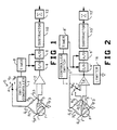
- a filament F is shown as being contained in a cavity C having an inlet port I, which can be connected to the output of a separation column, and an outlet port O.
- the filament F is made of material having a high resistive temperature coefficient so that its resistance changes significantly with temperature, and it is connected as one arm of a Wheatstone bridge having resistors R1, R2 and R3 as its other arms.
- the resistors R1, R2 and R3 have low temperature coefficients.
- the junction J F3 of the filament F and the resistor R3 is connected to ground, and the junction J12 of the resistors R1 and R2 is connected to an arm A of a switch S.
- the arm A is operated by a switch controller 1 so as to alternately be connected to a high voltage V P or a lower voltage VM .
- V M is so low that the current it causes to flow through the filament F does not significantly change its resistance or temperature.
- the junctions J F3 and J12 are the ends of one diagonal of the bridge to which operating voltages are applied.
- the inlet port I is connected to the output of a separation column, not shown.
- One input of a differential amplifier 2 is connected to a junction J 1F of the resistor R1 and the filament F, and its other input is connected to a junction J23 of the resistors R2 and R3.
- the output of the amplifier 2 is connected to a sample-and-hold device 4, and its output is connected to an A/D converter 6.
- a timer 8 causes the switch controller 1 to alternate the arm A between V P and V M at such a rate that a number of alternations occur during each peak.
- the timer 8 also causes the sample-and-hold device 4 and the A/D converter 6 to operate after each change in the position of the switch S.
- a means 10 provides a signal indicative of the difference between successive samples, and the differences are summed in a summer 12 so as to yield a signal corresponding to the thermal conductivity of a peak in the output of a separation column.
- FIGURE 1 operates as follows. Whenever the lower voltage V M is applied across one diagonal J12, J F3 , insufficient current flows through the filament F to change its resistance or temperature by a significant amount. The gases in the cell, the cell walls and the filament F all have the same temperature. Therefore, the voltage across the other diagonal J 1F , J23 will be zero if the resistance of the filament F is the same as the resistances of R1, R2 and R3; but if it is different, the bridge is imbalanced so that the voltage across the said other diagonal will have a value dependent on the temperature involved. Either value, in effect becomes the baseline value.
- the filament F When the higher voltage V P is applied, the filament F is heated to a higher temperature so as to imbalance the bridge by an amount determined by the resistance attained by the filament F, and this in turn depends on the thermal conductivity of the gases in the cell C at the time.
- the sample-and-hold device 4 At each change in the position of the arm A, the sample-and-hold device 4 is operated, and the A/D device 6 stores each sample in digital form.
- the means 10 provides signals respectively corresponding to the difference between the voltage across the diagonal J 1F , J23 for successive samples, i.e., between a sample taken when VM is applied across the diagonal J12 and J F3 , and an adjacent sample taken when V P is applied across the same diagonal.
- a Wheatstone bridge circuit is formed by resistors R1 ⁇ , R2 ⁇ and R3 ⁇ and a filament F ⁇ that is mounted within a cavity C ⁇ .
- the cavity C ⁇ has an inlet port I ⁇ that is to be connected to the output of a separation column and an outlet port O ⁇ .
- junction J 1F ⁇ of the filament F ⁇ and the resistor R1 ⁇ is connected to the inverting input of an operational amplifier 14; and the non- inverting input of the operational amplifier is connected to an arm a of a switch s that is operated by a controller 1 ⁇ so as to alternate between a point of voltage V M and the junction J23 ⁇ of the resistors R2 ⁇ and R3 ⁇ .
- the inputs of the operational amplifier 14 are connected across a diagonal of the bridge at which its output voltage appears.
- junction J F3 ⁇ of the filament F ⁇ and the resistor R3 ⁇ is connected to ground and the junction J12 ⁇ of the resistors R1 ⁇ and R2 ⁇ is connected to the output of the operational amplifier 14 so that the voltage at that output is applied across the other diagonal of the bridge, i.e., J12 ⁇ , J F3 ⁇ .
- a limiter 16 that is connected between the output of the operational amplifier 14 and ground prevents the output from becoming zero volts or negative.
- An A/D converter 6 ⁇ , a means 10 ⁇ and a summer 12 ⁇ cooperate in the same manner as the corresponding devices 6, 10 and 12 of FIGURE 1 to produce a signal indicative of the thermal conductivity of a peak.
- a timer 8 ⁇ causes the controller 1 ⁇ to alternate the arm a of the switch s between contact with a source V M of low voltage and the junction J23 ⁇ of the resistors R2 ⁇ and R3 ⁇ , and makes the sample-and-hold device 4 ⁇ sample the signal at the output of the operational amplifier 14, and the A/D converter 6 ⁇ sample the output of the sample-and-hold device 4 ⁇ after each alternation of the switch s.
- the operation of the embodiment illustrated by FIGURE 2 is as follows.
- the output voltage of the amplifier 14 is equal to R1 ⁇ /F ⁇ times V M and is an indication of the initial imbalance. Since the resistance of the filament F ⁇ will change with temperature of the gases in the cell C ⁇ , this voltage will vary accordingly.
- the arm a of the switch s is connected to the junction J23 ⁇ , the initial voltage across the diagonal J12 ⁇ , J F3 ⁇ is that permitted by the limiter 16, and the inputs of the operational amplifier 14 are connected across the diagonal J F1 ⁇ , J23 ⁇ . In this situation, the amplifier 14 will provide an output voltage required to heat the filament F ⁇ to such temperature that its resistance will bring the bridge into balance.
- the variation in the voltage at the output of the amplifier 14 during alternate positions of the arm a of the switch s is processed by the S/H device 4 ⁇ , the A/D device 6 ⁇ , the subtractor 10 ⁇ and the summer 12 ⁇ to derive the output signal of the detector.
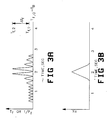
- the output voltage vs. time of the amplifiers 2 and 14 is as indicated in FIGURE 3A when the carrier gas has a thermal conductivity greater than that of any constituent gas to be encountered.
- the output of either of the amplifiers 2 or 14 increases to a value depending on the concentration of constituent gas in the cavity; and when the lower voltage is applied across the bridge, the output of either of the amplifiers 2 or 14 decreases to a value depending on how close the lower voltage applied across the bridge is to a value that does not increase the temperature of the filament.
- the ordinates of FIGURE 3A correspond to the changes in the resistance of the filament F and thus the changes in imbalance in the bridge when different voltages V M and V P are applied across it; and in FIGURE 2, the ordinates of FIGURE 3A correspond to the changes in voltage that must be applied across the bridge in order to keep it in balance.
- the waveform in FIGURE 3B is the sum of the difference between the amplitudes of successive pulses of FIGURE 3A that appear at the output of the subtractors 10 and 10 ⁇ .
- the pulses When the cavity C contains pure carrier gas, the pulses have constant amplitude so that the output of the subtractors 10 and 10 ⁇ is zero. Should the temperatures of the wall of the cavities C or C ⁇ have a different fixed value during a peak, the tops of the pulses will change in value, but so will the troughs where the voltage V M is applied.
- the subscript "0" indicates a situation where the applied voltage is so small as not to change the temperature of the filament by a significant amount
- the subscript "1” indicates a situation where the applied voltage makes a significant change in the temperature of the filament and the cavity containing the filament is filled with carrier gas
- the subscript "2” indicates a situation where the applied voltage makes a significant change in the resistance of the filament and the cavity contains a mixture of carrier gas and constituent or analyte gas.
- the subscript "f” refers to filament.
- Various constants used in the equations are defined immediately below. the bridge in order to keep it in balance.
- the waveform in FIGURE 3B is the sum of the difference between the amplitudes of successive pulses of FIGURE 3A that appear at the output of the subtractors 10 and 10 ⁇ .
- the pulses When the cavity C contains pure carrier gas, the pulses have constant amplitude so that the output of the subtractors 10 and 10 ⁇ is zero. Should the temperatures of the wall of the cavities C or C ⁇ have a different fixed value during a peak, the tops of the pulses will change in value, but so will the troughs where the voltage V M is applied.
- ⁇ c thermal conductivity of carrier gas
- Xc mole fraction of carrier gas
- ⁇ a thermal conductivity of analyte
- Xa mole fraction of analyte
- G cell geometry factor
- P power
- J conversion factor
- q rate of heat loss from filament
- m molar flow rate
- C p heat capacitance, molar
- ⁇ T ⁇ and ⁇ T ⁇ gas temperature differential between incoming and outgoing streams
- S ⁇ and S ⁇ all other heat losses, including radiation and end losses
- ⁇ T difference in temperature of filament and cavity wall
- ⁇ T f change in filament temperature
- ⁇ c,a thermal conductivity of mixture of carrier and constituent or analyte gases.
- the heat flows q1 and q2 from the filament to the wall of the cavity through carrier gas and carrier gas containing analyte gas respectively are substantially equal for the following reason.
- the heat flow is proportional to the thermal conductivity of the gas in the cavity; but the temperature of the filament varies inversely with the thermal conductivity so as to cause the temperature differential to change in like manner and make a compensating change in the heat flow.
- the compensation may not be perfect if the differences in the thermal conductivities of the gases is too large because the difference in temperature may affect the thermal conductivities. In most cases, however, this has a small effect.
- thermo energy there are other ways of alternately introducing different amounts of thermal energy into an analyte and measuring its thermal conductivity.
- Two probes could be provided: one for alternately introducing different amounts of thermal energy, and the other at a given distance from the first for measuring the amount of thermal energy passed through fluid between them.
- a single probe could be used for alternately introducing different amounts of thermal energy into the fluid and for measuring the rate at which the thermal energy escaped from the probe.
Landscapes
- Chemical & Material Sciences (AREA)
- General Health & Medical Sciences (AREA)
- Life Sciences & Earth Sciences (AREA)
- Health & Medical Sciences (AREA)
- Analytical Chemistry (AREA)
- Biochemistry (AREA)
- Physics & Mathematics (AREA)
- General Physics & Mathematics (AREA)
- Immunology (AREA)
- Pathology (AREA)
- Chemical Kinetics & Catalysis (AREA)
- Electrochemistry (AREA)
- Investigating Or Analyzing Materials By The Use Of Electric Means (AREA)
- Investigating Or Analyzing Materials Using Thermal Means (AREA)
Applications Claiming Priority (2)
| Application Number | Priority Date | Filing Date | Title |
|---|---|---|---|
| US06/885,120 US4735082A (en) | 1986-07-14 | 1986-07-14 | Pulse modulated thermal conductivity detector |
| US885120 | 1992-05-18 |
Publications (2)
| Publication Number | Publication Date |
|---|---|
| EP0254906A2 true EP0254906A2 (de) | 1988-02-03 |
| EP0254906A3 EP0254906A3 (de) | 1989-07-19 |
Family
ID=25386186
Family Applications (1)
| Application Number | Title | Priority Date | Filing Date |
|---|---|---|---|
| EP87109614A Ceased EP0254906A3 (de) | 1986-07-14 | 1987-07-03 | Pulsmodulierter Wärmeleitfähigkeitsdetektor |
Country Status (3)
| Country | Link |
|---|---|
| US (1) | US4735082A (de) |
| EP (1) | EP0254906A3 (de) |
| JP (1) | JPS6394144A (de) |
Cited By (2)
| Publication number | Priority date | Publication date | Assignee | Title |
|---|---|---|---|---|
| EP0527987B1 (de) * | 1991-03-07 | 1995-11-02 | Ritschel, Manfred Dr. rer. nat. | Verfahren zur bestimmung von chemischen und/oder physikalischen eigenschaften einer gasatmosphäre |
| WO2008101822A1 (fr) * | 2007-02-15 | 2008-08-28 | Neroxis Sa | Capteur de gaz thermique |
Families Citing this family (36)
| Publication number | Priority date | Publication date | Assignee | Title |
|---|---|---|---|---|
| US4829810A (en) * | 1988-01-04 | 1989-05-16 | Aluminum Company Of America | Filament drive circuit |
| US5038304A (en) * | 1988-06-24 | 1991-08-06 | Honeywell Inc. | Calibration of thermal conductivity and specific heat devices |
| US4944035A (en) * | 1988-06-24 | 1990-07-24 | Honeywell Inc. | Measurement of thermal conductivity and specific heat |
| US4956793A (en) * | 1988-06-24 | 1990-09-11 | Honeywell Inc. | Method and apparatus for measuring the density of fluids |
| US4876887A (en) * | 1988-06-27 | 1989-10-31 | Mickler Brian E | Thermal flux mass flowmeter |
| US5187674A (en) * | 1989-12-28 | 1993-02-16 | Honeywell Inc. | Versatile, overpressure proof, absolute pressure sensor |
| US5379630A (en) * | 1993-06-28 | 1995-01-10 | Hewlett-Packard Company | Thermal conductivity detector |
| US5551283A (en) * | 1993-08-10 | 1996-09-03 | Ricoh Seiki Company, Ltd. | Atmosphere measuring device and flow sensor |
| EP0698786A1 (de) * | 1994-08-23 | 1996-02-28 | RICOH SEIKI COMPANY, Ltd. | Gas- und Durchflusssensor |
| FI113405B (fi) * | 1994-11-02 | 2004-04-15 | Jarmo Juhani Enala | Reaaliaikainen mittausmenetelmä |
| CA2184055C (en) * | 1994-12-29 | 2001-12-18 | Mitsuteru Kimura | Humidity sensor |
| US5587520A (en) * | 1995-09-29 | 1996-12-24 | Hewlett-Packard Company | Thermal conductivity detector |
| US6079253A (en) * | 1997-12-31 | 2000-06-27 | Honeywell Inc. | Method and apparatus for measuring selected properties of a fluid of interest using a single heater element |
| US6223593B1 (en) | 1997-12-31 | 2001-05-01 | Honeywell International Inc. | Self-oscillating fluid sensor |
| US6169965B1 (en) | 1997-12-31 | 2001-01-02 | Honeywell International Inc. | Fluid property and flow sensing via a common frequency generator and FFT |
| US6393894B1 (en) | 1999-07-27 | 2002-05-28 | Honeywell International Inc. | Gas sensor with phased heaters for increased sensitivity |
| US6422088B1 (en) | 1999-09-24 | 2002-07-23 | Denso Corporation | Sensor failure or abnormality detecting system incorporated in a physical or dynamic quantity detecting apparatus |
| US6701774B2 (en) * | 2000-08-02 | 2004-03-09 | Symyx Technologies, Inc. | Parallel gas chromatograph with microdetector array |
| US6502459B1 (en) | 2000-09-01 | 2003-01-07 | Honeywell International Inc. | Microsensor for measuring velocity and angular direction of an incoming air stream |
| US6357279B1 (en) | 2001-01-29 | 2002-03-19 | Leco Corporation | Control circuit for thermal conductivity cell |
| AU2003272721A1 (en) * | 2002-09-27 | 2004-04-19 | Honeywell International Inc. | Phased micro analyser |
| US7104112B2 (en) * | 2002-09-27 | 2006-09-12 | Honeywell International Inc. | Phased micro analyzer IV |
| US7494326B2 (en) * | 2003-12-31 | 2009-02-24 | Honeywell International Inc. | Micro ion pump |
| US7000452B2 (en) * | 2002-09-27 | 2006-02-21 | Honeywell International Inc. | Phased micro fluid analyzer |
| US20040224422A1 (en) * | 2002-09-27 | 2004-11-11 | Ulrich Bonne | Phased micro analyzer III, IIIA |
| US20050063865A1 (en) * | 2002-09-27 | 2005-03-24 | Ulrich Bonne | Phased VII micro fluid analyzer having a modular structure |
| US7530257B2 (en) * | 2002-09-27 | 2009-05-12 | Honeywell International Inc. | Phased micro analyzer VIII |
| US20040223882A1 (en) * | 2002-09-27 | 2004-11-11 | Ulrich Bonne | Micro-plasma sensor system |
| US9029028B2 (en) | 2003-12-29 | 2015-05-12 | Honeywell International Inc. | Hydrogen and electrical power generator |
| US20050142035A1 (en) * | 2003-12-31 | 2005-06-30 | Ulrich Bonne | Micro-discharge sensor system |
| US7578167B2 (en) * | 2005-05-17 | 2009-08-25 | Honeywell International Inc. | Three-wafer channel structure for a fluid analyzer |
| US7502109B2 (en) * | 2005-05-17 | 2009-03-10 | Honeywell International Inc. | Optical micro-spectrometer |
| CN101300486B (zh) | 2005-09-02 | 2013-07-24 | Abb公司 | 模块化气相色谱仪 |
| GB0605683D0 (en) * | 2006-03-21 | 2006-05-03 | Servomex Group Ltd | Thermal conductivity sensor |
| US7670046B2 (en) * | 2007-06-18 | 2010-03-02 | Iliya Mitov | Filled hotwire elements and sensors for thermal conductivity detectors |
| DE102023113676A1 (de) * | 2023-05-25 | 2024-11-28 | Infineon Technologies Ag | Methods for operating thermal conductivity sensors |
Family Cites Families (12)
| Publication number | Priority date | Publication date | Assignee | Title |
|---|---|---|---|---|
| US3913379A (en) * | 1973-10-18 | 1975-10-21 | Tibor Rusz | Dynamic gas analyzer |
| JPS5289999A (en) * | 1975-12-31 | 1977-07-28 | Gen Monitors | Pulse duration modulating apparatus for heating a sensing element |
| DE2627916C3 (de) * | 1976-06-22 | 1978-12-21 | Auergesellschaft Gmbh, 1000 Berlin | Schaltungsanordnung für eine Meßbrücke eines Gasspürgerätes |
| US4254654A (en) * | 1976-10-07 | 1981-03-10 | Hewlett-Packard Company | Modulated fluid detector |
| CH606915A5 (de) * | 1976-10-22 | 1978-11-15 | Landis & Gyr Ag | |
| JPS5917852B2 (ja) * | 1977-02-07 | 1984-04-24 | 日本電気株式会社 | 半導体装置 |
| US4063447A (en) * | 1977-03-14 | 1977-12-20 | Honeywell, Inc. | Bridge circuit with drift compensation |
| US4164862A (en) * | 1977-11-25 | 1979-08-21 | Jackson Milton L | Multicomponent thermal conductivity analyzer |
| US4185490A (en) * | 1978-10-06 | 1980-01-29 | Hewlett-Packard Company | Phase discrimination in modulated thermal conductivity detector |
| US4461166A (en) * | 1982-02-26 | 1984-07-24 | Delta Associates, Inc. | Dynamic current drive method for powering thermal conductivity detectors |
| DE3219372A1 (de) * | 1982-05-19 | 1983-11-24 | Siemens AG, 1000 Berlin und 8000 München | Messanordnung mit einer brueckenschaltung |
| JPS60142242A (ja) * | 1983-12-28 | 1985-07-27 | Shimadzu Corp | 熱伝導型検出器 |
-
1986
- 1986-07-14 US US06/885,120 patent/US4735082A/en not_active Expired - Fee Related
-
1987
- 1987-07-03 EP EP87109614A patent/EP0254906A3/de not_active Ceased
- 1987-07-14 JP JP62176918A patent/JPS6394144A/ja active Pending
Cited By (4)
| Publication number | Priority date | Publication date | Assignee | Title |
|---|---|---|---|---|
| EP0527987B1 (de) * | 1991-03-07 | 1995-11-02 | Ritschel, Manfred Dr. rer. nat. | Verfahren zur bestimmung von chemischen und/oder physikalischen eigenschaften einer gasatmosphäre |
| WO2008101822A1 (fr) * | 2007-02-15 | 2008-08-28 | Neroxis Sa | Capteur de gaz thermique |
| AU2008217071B2 (en) * | 2007-02-15 | 2011-04-07 | Neroxis Sa | Thermal gas sensor |
| US8161795B2 (en) | 2007-02-15 | 2012-04-24 | Neroxis Sa | Thermal gas sensor |
Also Published As
| Publication number | Publication date |
|---|---|
| JPS6394144A (ja) | 1988-04-25 |
| EP0254906A3 (de) | 1989-07-19 |
| US4735082A (en) | 1988-04-05 |
Similar Documents
| Publication | Publication Date | Title |
|---|---|---|
| EP0254906A2 (de) | Pulsmodulierter Wärmeleitfähigkeitsdetektor | |
| Manz et al. | Electroosmotic pumping and electrophoretic separations for miniaturized chemical analysis systems | |
| US6144447A (en) | Apparatus for continuously measuring physical and chemical parameters in a fluid flow | |
| JPS6132369Y2 (de) | ||
| GB1565444A (en) | Temperature control apparatus | |
| Prest et al. | Single electrode conductivity detection for electrophoretic separation systems | |
| US3712116A (en) | Method and apparatus for detecting liquid compositions by thermal conductivity | |
| Kawaguchi et al. | Fully automated apparatus to measure the thermal conductivity of liquids by the transient hot‐wire method | |
| Rowley et al. | Ternary liquid mixture thermal conductivities | |
| Rolfson et al. | Automatic Osmometer for Determination of Number Average Molecular Weights of Polymers. | |
| US4120659A (en) | Sulfur analysis | |
| Thiel et al. | Determination of binary diffusion coefficients in liquid nonelectrolyte mixtures using the Taylor dispersion technique | |
| JPS6254152A (ja) | 熱電対を利用した測定方法及びセンサ | |
| Gale et al. | Electrical conductivity particle detector for use in biological and chemical micro-analysis systems | |
| Fortier et al. | Direct continuous measurements of thermal expansion coefficients of liquids and solids using flow microcalorimetry | |
| Pigott et al. | Observed behavior of a thermistor bead flow meter | |
| Rawlins | Some new methods for measuring the components of water potential | |
| SU1037762A1 (ru) | Датчик определени концентрации газа в газожидкостном потоке | |
| Chrenko | Infrared Microcell. | |
| Kaniansky et al. | Instrumentation for capillary isotachophoresis | |
| SU714260A1 (ru) | Диэлькометрический концентратомер | |
| SU1599752A1 (ru) | Способ Блаженко-Дубовского измерени химического состава среды и устройство дл его осуществлени | |
| SU1377676A1 (ru) | Термохимический газоанализатор | |
| SU1308002A1 (ru) | Электрохимический анализатор жидкости | |
| TW487802B (en) | A thermal conductivity gas analyzer |
Legal Events
| Date | Code | Title | Description |
|---|---|---|---|
| PUAI | Public reference made under article 153(3) epc to a published international application that has entered the european phase |
Free format text: ORIGINAL CODE: 0009012 |
|
| AK | Designated contracting states |
Kind code of ref document: A2 Designated state(s): DE FR GB IT |
|
| PUAL | Search report despatched |
Free format text: ORIGINAL CODE: 0009013 |
|
| AK | Designated contracting states |
Kind code of ref document: A3 Designated state(s): DE FR GB IT |
|
| 17P | Request for examination filed |
Effective date: 19900115 |
|
| 17Q | First examination report despatched |
Effective date: 19910930 |
|
| STAA | Information on the status of an ep patent application or granted ep patent |
Free format text: STATUS: THE APPLICATION HAS BEEN REFUSED |
|
| 18R | Application refused |
Effective date: 19930406 |
|
| RIN1 | Information on inventor provided before grant (corrected) |
Inventor name: KOLLOFF, RICHARD H. |