EP0254558B1 - Method for assembling actuator mechanism of a magnetic disk apparatus - Google Patents
Method for assembling actuator mechanism of a magnetic disk apparatus Download PDFInfo
- Publication number
- EP0254558B1 EP0254558B1 EP87306497A EP87306497A EP0254558B1 EP 0254558 B1 EP0254558 B1 EP 0254558B1 EP 87306497 A EP87306497 A EP 87306497A EP 87306497 A EP87306497 A EP 87306497A EP 0254558 B1 EP0254558 B1 EP 0254558B1
- Authority
- EP
- European Patent Office
- Prior art keywords
- head
- arm
- assembly
- arms
- holes
- Prior art date
- Legal status (The legal status is an assumption and is not a legal conclusion. Google has not performed a legal analysis and makes no representation as to the accuracy of the status listed.)
- Expired - Lifetime
Links
Images








Classifications
-
- G—PHYSICS
- G11—INFORMATION STORAGE
- G11B—INFORMATION STORAGE BASED ON RELATIVE MOVEMENT BETWEEN RECORD CARRIER AND TRANSDUCER
- G11B5/00—Recording by magnetisation or demagnetisation of a record carrier; Reproducing by magnetic means; Record carriers therefor
- G11B5/48—Disposition or mounting of heads or head supports relative to record carriers ; arrangements of heads, e.g. for scanning the record carrier to increase the relative speed
- G11B5/50—Interchangeable mountings, e.g. for replacement of head without readjustment
-
- G—PHYSICS
- G11—INFORMATION STORAGE
- G11B—INFORMATION STORAGE BASED ON RELATIVE MOVEMENT BETWEEN RECORD CARRIER AND TRANSDUCER
- G11B5/00—Recording by magnetisation or demagnetisation of a record carrier; Reproducing by magnetic means; Record carriers therefor
- G11B5/48—Disposition or mounting of heads or head supports relative to record carriers ; arrangements of heads, e.g. for scanning the record carrier to increase the relative speed
- G11B5/54—Disposition or mounting of heads or head supports relative to record carriers ; arrangements of heads, e.g. for scanning the record carrier to increase the relative speed with provision for moving the head into or out of its operative position or across tracks
- G11B5/55—Track change, selection or acquisition by displacement of the head
- G11B5/5521—Track change, selection or acquisition by displacement of the head across disk tracks
-
- Y—GENERAL TAGGING OF NEW TECHNOLOGICAL DEVELOPMENTS; GENERAL TAGGING OF CROSS-SECTIONAL TECHNOLOGIES SPANNING OVER SEVERAL SECTIONS OF THE IPC; TECHNICAL SUBJECTS COVERED BY FORMER USPC CROSS-REFERENCE ART COLLECTIONS [XRACs] AND DIGESTS
- Y10—TECHNICAL SUBJECTS COVERED BY FORMER USPC
- Y10T—TECHNICAL SUBJECTS COVERED BY FORMER US CLASSIFICATION
- Y10T29/00—Metal working
- Y10T29/49—Method of mechanical manufacture
- Y10T29/49002—Electrical device making
- Y10T29/4902—Electromagnet, transformer or inductor
- Y10T29/49021—Magnetic recording reproducing transducer [e.g., tape head, core, etc.]
- Y10T29/49025—Making disc drive
-
- Y—GENERAL TAGGING OF NEW TECHNOLOGICAL DEVELOPMENTS; GENERAL TAGGING OF CROSS-SECTIONAL TECHNOLOGIES SPANNING OVER SEVERAL SECTIONS OF THE IPC; TECHNICAL SUBJECTS COVERED BY FORMER USPC CROSS-REFERENCE ART COLLECTIONS [XRACs] AND DIGESTS
- Y10—TECHNICAL SUBJECTS COVERED BY FORMER USPC
- Y10T—TECHNICAL SUBJECTS COVERED BY FORMER US CLASSIFICATION
- Y10T29/00—Metal working
- Y10T29/53—Means to assemble or disassemble
- Y10T29/5313—Means to assemble electrical device
- Y10T29/53165—Magnetic memory device
Definitions
- This invention relates to a method for assembling an actuator mechanism of a magnetic disk apparatus.
- the actuator mechanism in this type of magnetic disk apparatus has conventionally been structured of several component parts from its rotary center upto its magnetic head for recording and playing back the information.
- the actuator mechanism in such a type of magnetic disk apparatus is constructed as follows.
- This actuator mechanism serves to move a plurality of magnetic heads for writing in and reading out the data respectively for a plurality of magnetic disks which are arranged coxially and rotated in synchronization to each other.
- Every magnetic heads are mounted on the tips of respective suspensions.
- An arm mounting section is formed at the other end of respective suspensions. Through-holes are provided to each arm mounting section, and the head assembly is comprised of magnetic head suspension and arm mounting section.
- Each head assembly is fixed by arranging the through-holes on arm mounting section in correspondence to the tapped holes formed at the tip of plurality of split head arms and by screwing the screws into the tapped holes.
- Each head arm mounted to each head assembly is positioned in an identical direction onto the arm supporting block which has been arranged rotably onto the shaft, and is fixed thereon by bolts and nuts.
- a voice coil structuring a magnetic circuit is provided to the arm supporting block, and is arranged between magnet and yoke.
- the through-holes which has been formed on the arm mounting section of head assembly, shall be arranged in correspondence to the tapped holes on each split head arm. Then, screw the thread into tapped hole to fix each head assembly to the head arm.
- respective head arms fitted with each head assembly shall be arranged in identical direction and at a given interval to each other onto the arm supporting block which has been installed rotatably onto the shaft. Further, at this time, its positioning shall be made in a way that the magnetic head at tip of each head assembly shall be arranged at the designated place on magnetic disk. And, in this state, the head arm shall be fixed to the arm supporting block by use of screws.
- the actuator mechanism of magnetic disk apparatus which has been structured in this way serves to move the magnetic head on the magnetic disk (making the head accessible to the disk) through head arm and suspension as the arm supporting block is rotated by the magnetic circuit.
- the arm mounting section of suspension fitted with respective magnetic heads is connected by means of screws onto a plurality of split head arms which are connected integrally to the arm supporting block by use of screws, and hence there appear thermal expansion and distortion to the connected area between arm supporting block and head arm on account of the temperature change inside the magnetic disk unit main body or such environmental changes as vibrations or shocks from external side, thereby the magnetic head at tip of suspension connected to the tip of head arm is likely to deviate out of the given position, thus involving a problematic point of causing problems such as off-track.
- a magnetic disk apparatus comprising: a plurality of magnetic disks stacked concentrically on a rotary shaft and having recording surfaces for recording data respectively, a plurality of head assemblies, each having a magnetic head means for reading data from and writing data on said magnetic disks and head supporting means for supporting said magnetic head means, driving means for moving said head assemblies along said recording surfaces and positioning said head assemblies to a position of said recording surface, carriage means for supporting said head assemblies, which has a plurality of assembly supporting means each for supporting at least one of said head assembly and base means for conjoining each of said assembly supporting means, said base means being connected to said moving means, and connecting means for connecting said head supporting means of said head assemblies to said assembly supporting means, each of said magnetic head means being disposed over one of said recording surfaces respectively.
- the invention provides a method for assembly an actuator mechanism, as defined in Claim 1 below.
- This invention is capable not only of decreasing the required number of parts by integrally forming a plurality of head arms with the arm supporting block, but also obtaining stable characteristics by simplifying the head positioning process.
- Fig. 1 is a partially disassembled perspective view showing the actuator mechanism of magnetic disk apparatus as the 1st embodiment of the present invention
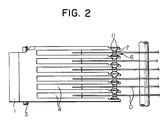
- Fig. 2 is a side view of Fig. 1
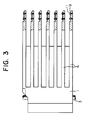
- Fig. 3 is a partial side sectional view of Fig. 1.
- the arm supporting block 1 as the assembly supporting means is installed rotably onto the shaft 3 formed on the base 2.
- a plurality of head arms 4 are integrally built up in the identical direction.
- assembly supporting means 200 are provided in the identical straight line across the rotary face.
- a tapped hole 5 is provided on identical straight line.
- the head assembly 6 includes the magnetic head 7 for writing in and reading out the data for the magnetic disk D, the suspension 8 as the supporiting means for supporting the magnetic head 7 with flexibility, and the arm mounting section 9 which is provided onto the suspension 8.
- the arm mounting section 9 includes the through-holes 10 which are corresponding to the tapped holes 5 of the head arm 4.
- the thread member 11 includes the head section 13 in which the joint groove 12 being joined to the screw tightening joint section of a screwdriver (described later) is formed, and the thread section 14 joining to the tapped holes 5.
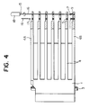
- the actuator mechanism of the magnetic disk apparatus to be structured in this way can be assembled as shown in Fig. 4.
- numeral 15 designates the screwdriver which includes a shaft section 16 made of, for example, super hard metal, the screw tightening joint section 17 formed at tip of the shaft section 16, and grip portion 18 to which the shaft section is fitted.
- the shaft section 16 has an outside diameter which can be inserted into respective tapped holes 5 on identical straight line formed on each of the aforementioned head arms 4.
- the shaft section 16 of the screwdriver 15 is to be inserted toward into the tapped hole 5 of the head arm 4A through the other side tapped hole 5 of the head arm 4B.
- the through-holes 10 on arm mounting section 9 of the head assembly 6 shall be arranged in correspondence to the tapped holes 5 of head arm 4B on the other side.
- the thread section 14 of thread member 11 shall be arranged toward the tapped holes 5 on head arms 4 from the through-holes 10 on arm mounting section 9, the joint section 17 of screwdriver 15 shall be applied to the joint groove 12 at a head section 13 of the thread member 11, and the screwdriver 15 shall be turned to join the thread member 11.
- the head assembly 6 can be connected to the head arms 4.
- the through-holes 10 on the arm mounting section 9 of the head assembly 6 shall be arranged in correspondence to the tapped holes 5 on head arms 4 adjacent to the head arms 4 to which this head assembly 6 is locked with screws, and they shall be locked by use of screws in the same way as the assembling method mentioned above. And the head assembly 6 shall sequentially be connected with screws onto the head arms 4 toward the head arms 4B on one side from the head arms 4A on the other side.
- this embodiment provides a simple structure and the positional deviation of magnetic head attributable to environmental changes like temperature fluctuation can also be prevented effectively because this employs such a structure that the head assembly 6 is connected by use of screws onto these head arms 4 where a plurality of head arms 4 are formed integrally onto the arm supporting block 1.
- the cost can be decreased because the required number of parts is curtailed down and their assembling work is simplified.
- Fig. 5 is a perspective view for explaining the assembling unit suitable for assembling the actuator mechanism of the magnetic disk apparatus shown in Fig. 1
- Fig. 6 is a side view omitting the part of Fig. 5
- Fig. 7 is a plane view omitting the part of Fig. 5.
- numeral 21 designates the actuator main body.
- This actuator main body 21 is made, for example, of die-cast molding, wherein a plurality of head arms 22 are unified into the arm supporting block 23.
- the arm supporting block 23 is installed rotably to the shaft 24 of actuator stand (not shown), and a voice coil 25 is formed to the arm supporting block 23, while this voice coil 25 is constructed in the way that it is arranged between magnet (not shown) and yoke (not shown) which are provided on the actuator base.
- And numeral 26 indicates the head assembly to be fitted to the head arms 22, and the head assembly 26 includes the magnetic heads 27 for writing in and reading out the data for the magnetic disk not shown in the figure and the suspension 29 having the mounting section 28 where the magnetic head 27 is fitted to one end portion and the through-holes 28a and 28a are formed on the other end portion.
- numeral 30 is the base which incorporates thereon the actuator main body positioning mechanism 31 for positioning the head arms 22 of actuator main body 21, the head assembly positioning mechanism 32 for energizing and positioning the mounting section 28 of head assembly 26 in a given direction when mounting the head assembly 26 onto the tip of head arms 22, and the head separating mechanism 33 for spacing the respective magnetic heads 27 of head assembly 26 from each other when the head assembly 26 has been fixed to the head arms 22.
- Fig. 8 is a perspective view for explaining the actuator main body positioning mechanism 31.
- a plurality of protrusions 34, 34 and 34 are formed at given places on the base 30. These protrusions 34 are joined to the positioning concave grooves 35, 35 and 35 formed respectively to the actuator main body 21, and the actuator main body 21 is to be pressed against the base and retained thereon by use of a pressing mechanism 36 after the body has been positioned by the protrusion 34.
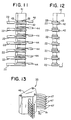
- Fig. 9 is a perspective view for explaining the head assembly positioning mechanism 32, Fig. 10 a plane view of Fig. 9, Fig. 11 a partial sectional front view showing the main part of Fig. 9, and Fig. 12 a side sectional view of Fig. 11.
- the concave section 37 is formed on the base 30, and the guide shafts 38 and 38 as well as the multi-thread screw 39 are arranged on this concave section 37.
- the guide shafts 38 and 38 as well as the multi-thread screw 39 are passed through and screwed into the head positioning block 40 so that the head positioning block 40 can be moved in the direction of arrows A1 and A2 by turning the handle section 39a of the multi-thread screw 39.
- the positioning strip 41 is formed on the head positioning block 40, and to this positioning strip 41 the notch sections 42, 42 ... for passing through the tips of respective head arms 22 in correspondence to these head arms.
- the mounting face 43 for positioning the mounting section 28 of the head assembly 26 is formed onto the positioning strip 41.
- the pressing arm 44 for pressing the mounting section 28 of head assembly 26 toward the aforementioned positioning face 43 is arranged to the positioning strip 41, and this pressing arm 44 is pressed by the dint of the spring 45.
- the head separating mechanism 33 is structured of the spacer support block 46 and the C-letter shaped spacer rings 47 which are arranged for free movement in the direction of arrows B1 and B2 onto the spacer support block 46.
- the spacer rings 47 can be stopped at an optional position by the spring plunger 48 arranged inside the spacer support block 46. And each spacer ring 47 is moved in arrow B1 direction so as to separate the magnetic heads 27 (so that the magnetic heads may not get in contact with each other) when the head assembly 26 is fixed to the head arms 22.
- the concave grooves 35, 35 and 35 of actuator main body 21 shall be joined, for positioning, to the protrusions 34, 34 and 34 on the base 30 which structures the actuator mechanism 31 thereon, and shall be pressed against the base by the pressing mechanism 36, for its retention thereon.
- manipulate the handle section 39a of head assembly positioning mechanism 32 to move the head positioning block 40 upto the given position in arrow A1 direction (which is the position where the through-hole [not shown] of the mounting section 28 of the head assembly 26 has coincided with the tapped hole [not shown] provided on the head arm 22).
- the mounting section 28 of head assembly 26 shall be arranged to the tip of head arms 22 on the side of base 30 (lower side), and the positioning shall be made by pressing the mounting section 28 toward the positioning face 43 of the positioning strip 41 formed on the head positioning block 40 by means of the energizing arm 44 which is provided on the head assembly positioning mechanism 32.
- the screw tightening tool 49 passing through the tapped hole 22a of the head arm 22 shall be inserted toward the tapped holes of head arms 22 on lower side (on the side of base 30) from the tapped holes of head arms 22 on upper side.
- the screws 51 and 51 shall be fitted to the screw supplying tool 50 which shall then be arranged to the through-hole (not shown) of the mounting section 28 on the head assembly 26 positioned as mentioned above, and the screws 51 and 51 shall be clamped and fixed to a given clamp force by use of the screw tightening tool 49.
- the spacer ring 47 on lower side on head separating mechanism 33 shall be moved toward arrow B1 direction to push down the suspension 29 of the head assembly 26.
- respective head assemblies 26 shall sequentially be fitted to the tip of respective head arms 22 in a similar way to the aforementioned assembling work.
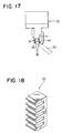
- the comb-shaped spacer 52 in its cross section which is shown in Fig. 18 shall be inserted into the position of the head separating spacer ring 47 arranged between suspensions 29 of each head assembly 26, while detaching the spacer ring 47, to saparate respective magnetic heads 27 from each other.
- the head positioning block 40 of the head assembly positioning mechanism 32 shall be moved toward arrow A2 derection by controlling the handle section 39a, and further the pressing mechanism 36 of actuation main body positioning mechanism 31 shall be released to remove the actuator main body 21 out of the base 30.
- this embodiment not only uses the actuator main body 21 in which a plurality of head arms 22 are formed integrally onto the arm support block 23 but also assembles by the above mentioned assembling method and assembling unit the head assembly 26 to the tip of respective head arms 22 of the actuator main body 21, the displacement of magnetic head can be prevented effectively and still more it is possible to attempt enhancing the assembling efficiency and reducing the cost, or protect the head effectively at time of assembly work.
- Fig. 21 is a disassembled perspective view of main part showing the 4th embodiment of the present invention
- Fig. 22 and Fig. 23 are side sectional views for explaining the assembled state.
- the same numerals are given to the parts in common with those in Fig. 19 and Fig. 20 for omission of an overlapped explanation.
- the revet through-holes 91 and 91 are formed at the tip of the head arm 63.
- the head assembly 65 includes the suspension 66b fitted with magnetic head 66a and the arm mounting section 66c installed to suspention 66b, while the fitting holes 92 and 92 meeting the above mentioned rivet through-holes 91 are provided on the arm mounting section 66c.
- Numeral 93 designates the rivet made of thermoplastic resin, and is formed to a hollow or a solid structure.
- the fitting holes 92 and 92 formed to the arm mounting section 66c of head assembly 65 are arranged in correspondence to the rivet through-holes 91 and 91 of head arm 63, wherein the rivets 93 and 93 are inserted into the rivet through-holes 91 from the fitting holes 92 and the tip of the rivets 93 is heated up and caulked as shown in Fig. 23.
- the fitting hole 92 and the rivet through-hole 93 are filled with the rivet 93 which has been fused.
- the heating means for rivet is not limited to a particular one, and for example, a super sonic wave or a laser beam can be used.
- the material for rivet 93 should preferably be the one with same thermal expansion coefficient as that for head arm 63.
- Fig. 24 is a disassembled perspective view of main part showing the 5th embodiment of the present invention
- Fig. 25 is a side sectional view for explaining the assembled state of Fig. 24.
- the identical notes are given to the parts in common with those in Fig. 19 through Fig. 23 for the sake of omission of an overlapped explanation.
- Fig. 24 is showing the embodiment in which the present invention is applied to the straight arm type carriage mechanism.
- the straight arm type carriage mechanism is disclosed in USP No. 4,620,251.
- the assembly supporting means 230 is formed at the tip of head arm 63.
- bush through-holes 101 and 101 are formed in the assembly supporting means 230.
- the head assembly 65 includes the magnetic head 66a, the suspension 66b fitted with the magnetic head 66a, and the arm mounting section 66c installed to suspension 66b, and the through-holes 102 and 102 meeting the above mentioned bush through-holes 101 are formed on the arm mounting section 66c.
- numeral 103 designates the bush which is structured of the flange 104 and the hollow shaft section 105.
- numeral 106 is a lock screw which can be screwed into the hollow shaft section 105 of bush 103.
- the bush through-hole 101 of the head arm 63 has the size meeting the outside diameter of hollow shaft section 105 of the bush 103, while the through-hole 103 of arm mounting section 66c has the size meeting the outside diameter of lock screw 106.
- the head assembly 65 is fixed to the head arm 63 by arranging the through-holes 102 and 102 formed on arm mounting section 66c of the head assembly 65 in correspondence to the bush through-holes 101 on the head arm 63, inserting the hollow shaft section 105 of the bush 103 into the bush through-hole 101 toward the side of the head assembly 65 from the side of the head arm 63, and also inserting the lock screw 106 into the through-hole 102 toward the side of the head arm 63 from the side of the head assembly 65, and by screwing the thread portion of the lock screw 106 into the hollow shaft section 105 of the bush 103.
- Fig. 26 is a disassembled perspective view of the main part showing the 6th embodiment of the present invention
- Fig. 27 is a side sectional view for explaining the assembled state of Fig. 26.
- the same numerals are given to the parts in common with those in Fig. 19 through Fig. 25 for the sake of omitting an overlapped explanation.
- the assembly supporting means 240 is installed at the tip of the head arm 63.
- the caulk pin through-holes 111 and 111 are formed in the assembly supporting means 240.
- the head assembly 65 includes the magnetic head 66a, the suspension 66b fitted with magnetic head 66b, and fitting holes 112 and 112 meeting the above mentioned caulk pin through-holes 111 are formed on the arm mounting section 66c.
- Numeral 113 is the caulk pin which is structured of the larger diameter section 114 and the caulking sections 115 and 115 of smaller diameter formed on both the side of larger diameter section 114.
- Numeral 116 is the washer capable of inserting the caulk section 115 of the caulk pin 113.
- the caulk pin through-hole 111 of the head arm 63 has the dimension meeting the outside diameter of larger diameter section 114 of the caulk pin 113, whereas the fitting hole 112 of the arm mounting section 66c is measured to meet the outside diameter of caulk section 115.
- the larger diameter section 114 of the caulk pin 113 is inserted into the caulk pin through-hole 111 of the head arm 63 while the fitting holes 112 and 112 formed on the arm mounting section 66c of the head assembly 65 is inserted into the caulking section 115 of the caulk pin 113, and still more the washer 116 is inserted into the caulking section 115 from the above mentioned arm mounting section 66c.
- the tip of caulking section 115 is expanded in Diameter, and the head assembly 65 is fixed to the head arm 63.
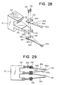
- Fig. 28 is a sectional perspective view showing the main part of the 7th embodiment of the present invention and Fig. 29 is a partial sectional side view of Fig. 28.
- Fig. 29 is a partial sectional side view of Fig. 28.
- the same codes are given to the parts in common to those in Fig. 19 through Fig. 26 so that an overlapped explanation can be omitted.
- the assembly supporting means 250 is installed to the tip of head arm 63, and the through-holes 120 and 120 penetrated across and on identical straight line to the rotary face of respective head arms 3 are built up on this supporting means 250.
- the head assembly 65 is structured of up-head assembly 65a and down-head assembly 65b.
- Each head assembly 65a and 65b includes the magnetic head 66a for writing in and reading out data respectively for the magnetic disk (not shown), the head suspension 66b to which the magnetic head 66a is fitted, and the arm mounting section 66c installed on the head suspension 66b.
- the fitting holes 122 in correspondence to the through-holes 120 of head arms 63 are formed on the arm mounting section 66c of the up-head assembly 65a, whereas, for example, the tapped holes 124 provided by tapping work are formed in correspondence to the through-holes 120 of the head arms 63 on the arm mounting section 66c of the down-head assembly.
- the up-head assembly 65a is arranged on the upper side of the head arms 63
- the down-head assembly 65b is arranged on the lower side of the head arms 63 so that the screws 126 may be penetrated into the through-holes 120 of the head arms 63 from the fitting holes 122 formed on the arm mounting section 66c of up-head assembly and screwed into the tapped holes 124 formed on the arm mounting section 66c of the down head assembly 65b.
- respective head assemblies 65a and 65b are mounted to the head arms 63.
- the up-head assembly 65a alone should be mounted to the head arms 63
- the plate nuts 128 shall be arranged to the lower side of head arms 63 and the screws 126 shall be screwed into the plate nuts 128.
- the head arms 63 shall be arranged to the lowest side of the arm supporting block 61 and the plate nuts 128 shall be arranged to the upper side thereof.
- the screws 126 shall be arranged to the arm mounting section 66c side of the up-head assembly 65a and shall be screwed into the plate nuts 128 by turning the screwdriver which is not shown in the figure, which can be penetrated into the fitting holes 122, through-holes 120 and tapped holes 124.
- the up-head assembly 65a can be fixed to the head arms 63 on the lowest side.
- the up-head assembly and the down-head assembly shall be aranged respectively to the upper side and the lower side of head arms 63 adjacent to the head arms 63 (in the middle stage) locking the up-head assembly 65a with screws, and they shall then be screwed into and fixed to the tapped holes 124 of arm mounting section 66c with a screwdriver (not shown) in the same assembling method as mentioned above by inserting and arranging the screws 126 into the fitting holes 124 of the arm mounting section 66c and the through-holes of the head arms 63. Therefore, respective head assemblies 65a and 65b shall be locked to the head arms 63 with screws sequentially toward the upper side head arms 63 from the lower side head arms 63 of the arm supporting block 61.
- Fig. 30 is a side sectional view showing the 8th embodiment of the present invention.
- the actuator fitting stand 132 is installed on the base 131, and the shaft 133 is arranged rotably between the base 131 and the actuator fitting stand 132 through bearings 134 and 134.
- the actuator main body 135 is fitted to this shaft 133.
- This actuator main body 135 is structured by fitting and laminating to the shaft 133 the arm supporting blocks 137 and 138 on which two head arms 136 are integrally formed, inserting the lock screws 140 into the through-holes 139 formed on the arm supporting block 137 and screwing the lock screws 140 into the tapped holes 141 formed on the arm supporting block 138.
- the assembly supporting means 260 are installed to the tips of head arms 136 of respective arm supporting blocks 137 and 138.
- the tapped holes 142 are formed on the supporting means 260.
- the head assembly 143 includes the magnetic head 144 for writing in and reading out data respectively for the magnetic disk D, the head suspension 145 equipped with magnetic head 144 and the arm mounting section 146 formed on head suspension 145, and the fitting holes 147 in correspondence to the tapped holes 142 of the head arm 136 are formed on the arm mounting section 146 of the head assembly 143.
- the arm mounting section 146 of the head assembly 143 is arranged respectively on both the external sides (upper and lower sides) of the arm supporting blocks 137 and 138, the screws 148 are inserted from the fitting hole 147 side of the arm mounting section 146, and respective head assemblies 143 are fitted to the head arms 136 by screwing the screws 148 into the tapped holes 142 of the head arm 136.
- the arm mounting section 146 of the head assembly 143 shall be arranged on the upper side head arms 136 of respective arm supporting blocks 137 and 138 while having the tapped holes 142 of the head arms 136 corresponded to the fitting holes 147 of arm mounting section 146. Then screw the screws 148 into the tapped holes 142 of head arms 138 using a screwdriver 149.
- the arm mounting section 146 of the head assembly 143 shall be arranged on the lower side of lower side head arms 138 of respective arm supporting blocks 137 and 138 while having the tapped holes 142 of head arms 136 corresponded to the fitting holes 142 of head arms 136 corresponded to the fitting holes 147 of arm mounting section 146.
- the screws 148 shall be screwed into the tapped holes 142 of head arms 136 by means of the screwdriver 149.
- the actuator main body 135 shall be constructed by fitting the arm supporting blocks 137 and 138, in which the head assembly 143 is locked to the head arms 136, to the shaft 133 with the arm supporting block 138 being arranged on lower side, by inserting the lock screws 140 into the through-holes 139 of upper arm mounting section 137 and screwing the lock screws 140 into the tapped holes 141 of lower side arm supporting block 138.
- Fig. 33 is a perspective view of the actuator mechanism showing the 9th embodiment of the present invention.
- the identical numerals are given to the parts in common with those in Fig. 19 through Fig. 26, so as to omit an overlapped explanation.
- a plurality of arms 63 are connected integrally to each other, and the carriage 300 and the block 310 arranged rotatably on the shaft 62 are constructed separately.
- the carriage 300 is coupled with the block 310 by use of screws 320.
- the arms 63 are formed integrally to each other. Consequently, the same effect as that being provided by other embodiments can be obtained.
- Fig. 34 is a partial sectional side view for explaining the 10th embodiment of the present invention, and stands for the embodiment in the case that the present invention is applied to the magnetic disk having a linear type actuator mechanism.
- the two magnetic disks 401 are stacked concentrically to the rotary shaft 400.
- a cylindrical rails 402 are installed in the direction crossing in right angle the axial direction P of rotary shaft 400.
- a moving section 404 is installed on the rails 402 via the bearings 403. The moving section 404 moves on the rails 402 by the drive mechanism which is not shown in the figure.
- the carriage 405 is installed on the moving section 404.
- the carriage 405 is fixed onto the moving section 404 by use of screws 406.
- the assembly supporting means 407 are installed at 3 places on the carriage 405. Respective assembly supporting means 407 are formed integrally into a unit. Each assembly supporting means 407 is formed in the direction R identical to the axial direction P of the rotary shaft 400 of the carriage 405.
- the tapped holes 408 are formed on each assembly supporting means 407.
- the tapped holes 408 are formed, on straight line and in the direction R identical to the axial direction P of rotary shaft 400 onto each assembly supporting means 407.
- the magnetic head 410 is arranged opposite to the recording face 409 of the magnetic disk 401.
- the magnetic head 410 is installed at one end of the head supporting section 411.
- the head supporting section 411 supports the magnetic head 410 with flexibility.
- the head supporting section 411 and the magnetic head 410 toghther constitutes the head assembly 412.
- the tapped through-holes are formed at the other end of the head supporting section 411, in correspondence to the tapped holes 408.
- the screws 413 pass through the through-holes and engage with the tapped holes 408 to connect to the head assembly 412 to the assembly supporting section 405.
- the present invention provides a simple structure and the positional deviation of magnetic head attributable to environmental changes like temperature fluctuation can also be prevented effectively.
- the cost can be decreased because the required number of parts is curtailed down and their assembling work is simplified.
- the present invention can be also applied to the actuator mechanism without arms (arm-less) which is not shown in the drawings. It is also possible that a plurality of assembly supporting means are mounted on one head arm. Further, it is possible in such a case that the assembly supporting means are arranged to toward the random direction respectively.
- the head assembly can be fitted to the assembly supporting means through the spacer or fitted directly not through the spacer.
- the material of the arm supporting block is not limited to the specific material. Aluminum, stainless steel, plastic, etc., can be used as its material.
Landscapes
- Supporting Of Heads In Record-Carrier Devices (AREA)
- Moving Of Heads (AREA)
Description
- This invention relates to a method for assembling an actuator mechanism of a magnetic disk apparatus.
- In recent years, in such information processing apparatus as a word processor and a personal computer, a magnetic disk apparatus is used as their external memory means.
- The actuator mechanism in this type of magnetic disk apparatus has conventionally been structured of several component parts from its rotary center upto its magnetic head for recording and playing back the information. The actuator mechanism in such a type of magnetic disk apparatus is constructed as follows.
- This actuator mechanism serves to move a plurality of magnetic heads for writing in and reading out the data respectively for a plurality of magnetic disks which are arranged coxially and rotated in synchronization to each other.
- Every magnetic heads are mounted on the tips of respective suspensions. An arm mounting section is formed at the other end of respective suspensions. Through-holes are provided to each arm mounting section, and the head assembly is comprised of magnetic head suspension and arm mounting section.
- Each head assembly is fixed by arranging the through-holes on arm mounting section in correspondence to the tapped holes formed at the tip of plurality of split head arms and by screwing the screws into the tapped holes.
- Each head arm mounted to each head assembly is positioned in an identical direction onto the arm supporting block which has been arranged rotably onto the shaft, and is fixed thereon by bolts and nuts.
- Also, a voice coil structuring a magnetic circuit is provided to the arm supporting block, and is arranged between magnet and yoke.
- Next, the assembling method of actuator mechanism of this magnetic disk will be described.
- First, the through-holes, which has been formed on the arm mounting section of head assembly, shall be arranged in correspondence to the tapped holes on each split head arm. Then, screw the thread into tapped hole to fix each head assembly to the head arm.
- Thereafter, respective head arms fitted with each head assembly shall be arranged in identical direction and at a given interval to each other onto the arm supporting block which has been installed rotatably onto the shaft. Further, at this time, its positioning shall be made in a way that the magnetic head at tip of each head assembly shall be arranged at the designated place on magnetic disk. And, in this state, the head arm shall be fixed to the arm supporting block by use of screws.
- The actuator mechanism of magnetic disk apparatus which has been structured in this way serves to move the magnetic head on the magnetic disk (making the head accessible to the disk) through head arm and suspension as the arm supporting block is rotated by the magnetic circuit.
- However, in the conventional type actuator mechanism of magnetic disk apparatus, the arm mounting section of suspension fitted with respective magnetic heads is connected by means of screws onto a plurality of split head arms which are connected integrally to the arm supporting block by use of screws, and hence there appear thermal expansion and distortion to the connected area between arm supporting block and head arm on account of the temperature change inside the magnetic disk unit main body or such environmental changes as vibrations or shocks from external side, thereby the magnetic head at tip of suspension connected to the tip of head arm is likely to deviate out of the given position, thus involving a problematic point of causing problems such as off-track.
- We acknowledge the disclosure in EP-A-0127058 and US-A-4107748 of a magnetic disk apparatus, comprising:
a plurality of magnetic disks stacked concentrically on a rotary shaft and having recording surfaces for recording data respectively,
a plurality of head assemblies, each having a magnetic head means for reading data from and writing data on said magnetic disks and head supporting means for supporting said magnetic head means,
driving means for moving said head assemblies along said recording surfaces and positioning said head assemblies to a position of said recording surface,
carriage means for supporting said head assemblies, which has a plurality of assembly supporting means each for supporting at least one of said head assembly and base means for conjoining each of said assembly supporting means, said base means being connected to said moving means, and
connecting means for connecting said head supporting means of said head assemblies to said assembly supporting means, each of said magnetic head means being disposed over one of said recording surfaces respectively. - A problem with all such mechanisms is in their assembly; the assembling work is complicated because a great number of parts with high accuracy are required.
- Accordingly, the invention provides a method for assembly an actuator mechanism, as defined in Claim 1 below.
- We acknowledge that co-pending European Patent Application No. 0208280 contributes to the state of the art regarding novelty (EPC Art. 54(3)) in relation to the designation of DE and GB but not IT. That Application discloses a method for assembling an actuator mechanism: that is, a preassembled head unit (7) is mounted in slots (17) of a head tower (10) and tightened by screws (18), the head tower (10) comprising at the free front end of the single beam section mounting means 16, which are formed as fork-shaped protrusions having receiving slots 17 for fastening
screws 18. As shown in Figure 2a, 2b and 2c, the slots arranged so that a comb-like mounting means 16 is obtained in the case of a larger number of head units (7). - This invention is capable not only of decreasing the required number of parts by integrally forming a plurality of head arms with the arm supporting block, but also obtaining stable characteristics by simplifying the head positioning process.
- In the accompanying drawings,
- Fig. 1 is a perspective view showing the actuator mechanism of magnetic disk apparatus;
- Fig. 2 is a side view of Fig. 1;
- Fig. 3 is a partial sectional side view of Fig. 1;
- Fig. 4 is a partial sectional side view for explaining the assembling unit of the actuator mechanism of Fig. 1;
- Fig. 5 is a perspective view for explaining the assembling unit used for assembling the actuator mechanism of Fig, 1;
- Fig. 6 is a partial sectional side view of Fig. 5;
- Fig. 7 is a plan view of Fig. 5;
- Fig. 8 is a perspective view for explaining the actuator main body positioning mechanism;
- Fig. 9 is a perspective view for explaining the head assembly positioning mechanism;
- Fig. 10 is a plan view of Fig 9;
- Fig. 11 is a partial sectional front view showing the major portion of Fig. 9;
- Fig. 12 is a side sectional view of Fig. 9;
- Fig. 13 is a perspective view showing the head separating mechanism;
- Fig. 14 is a side sectional view for explaining the screw tightening tool and assembling method;
- Fig. 15 is a side view showing the screw supplying tool;
- Fig. 16 is a plan view of Fig. 15;
- Fig. 17 is a plan view for explaining the screw supplying tool and assembling method;
- Fig. 18 is a perspective view for explaining the spacer for separating the heads;
- Fig. 21 is a disassembled perspective view of an actuator mechanism;
- Figs. 22 and 23 are sectional views for explaining the assembled state of Fig. 21;
- Fig. 24 is a disassembled perspective view of an actuator mechanism;
- Fig. 25 is a side sectional view of Fig. 24;
- Fig. 26 is a disassembled perpective view of an actuator mechanism;
- Fig. 27 is a side sectional view of Fig. 26;
- Fig. 28 is a disassembled perspective view of an actuator mechanism;
- Fig. 29 is a partial side sectional view of Fig. 28;
- Fig. 30 is a side sectional view of an actuator mechanism;
- Figs. 31 and 32 are partial side sectional views for explaining the assembled state of Fig. 30;
- Fig, 33 is a perspective view of an actuator mechanism; and
- Fig. 34 is a partial side sectional view of an actuator mechanism.
- Hereinafter, the embodiments of the present invention will be described in detail on the bases of the drawings.
- Fig. 1 is a partially disassembled perspective view showing the actuator mechanism of magnetic disk apparatus as the 1st embodiment of the present invention, Fig. 2 is a side view of Fig. 1, and Fig. 3 is a partial side sectional view of Fig. 1.
- In these figures, the arm supporting block 1 as the assembly supporting means is installed rotably onto the
shaft 3 formed on the base 2. To this arm supporting block 1, a plurality ofhead arms 4 are integrally built up in the identical direction. To the tip of thesehead arms 4, assembly supporting means 200 are provided in the identical straight line across the rotary face. On each of the assembly supporting means 200 a tapped hole 5 is provided on identical straight line. Thehead assembly 6 includes the magnetic head 7 for writing in and reading out the data for the magnetic disk D, the suspension 8 as the supporiting means for supporting the magnetic head 7 with flexibility, and thearm mounting section 9 which is provided onto the suspension 8. Thearm mounting section 9 includes the through-holes 10 which are corresponding to the tapped holes 5 of thehead arm 4. - And the through-
holes 10 formed on thearm mounting section 9 of thehead assembly 6 are arranged to the tapped holes 5 on thehead arm 4 and are connected with screws by the thread member 11. The thread member 11 includes thehead section 13 in which the joint groove 12 being joined to the screw tightening joint section of a screwdriver (described later) is formed, and thethread section 14 joining to the tapped holes 5. The actuator mechanism of the magnetic disk apparatus to be structured in this way can be assembled as shown in Fig. 4. - In Fig. 4, numeral 15 designates the screwdriver which includes a
shaft section 16 made of, for example, super hard metal, the screw tightening joint section 17 formed at tip of theshaft section 16, andgrip portion 18 to which the shaft section is fitted. Theshaft section 16 has an outside diameter which can be inserted into respective tapped holes 5 on identical straight line formed on each of theaforementioned head arms 4. - And the
shaft section 16 of thescrewdriver 15 is to be inserted toward into the tapped hole 5 of thehead arm 4A through the other side tapped hole 5 of thehead arm 4B. Then, the through-holes 10 onarm mounting section 9 of thehead assembly 6 shall be arranged in correspondence to the tapped holes 5 ofhead arm 4B on the other side. Then, thethread section 14 of thread member 11 shall be arranged toward the tapped holes 5 onhead arms 4 from the through-holes 10 onarm mounting section 9, the joint section 17 ofscrewdriver 15 shall be applied to the joint groove 12 at ahead section 13 of the thread member 11, and thescrewdriver 15 shall be turned to join the thread member 11. Thereby, thehead assembly 6 can be connected to thehead arms 4. - Next, the through-
holes 10 on thearm mounting section 9 of thehead assembly 6 shall be arranged in correspondence to the tapped holes 5 onhead arms 4 adjacent to thehead arms 4 to which thishead assembly 6 is locked with screws, and they shall be locked by use of screws in the same way as the assembling method mentioned above. And thehead assembly 6 shall sequentially be connected with screws onto thehead arms 4 toward thehead arms 4B on one side from thehead arms 4A on the other side. - Therefore, this embodiment provides a simple structure and the positional deviation of magnetic head attributable to environmental changes like temperature fluctuation can also be prevented effectively because this employs such a structure that the
head assembly 6 is connected by use of screws onto thesehead arms 4 where a plurality ofhead arms 4 are formed integrally onto the arm supporting block 1. In addition, the cost can be decreased because the required number of parts is curtailed down and their assembling work is simplified. - Next, the assembling unit and the assembling method of the actuator mechanism suitable for assembling the actuator mechanism shown in Fig. 1 will be described.
- Fig. 5 is a perspective view for explaining the assembling unit suitable for assembling the actuator mechanism of the magnetic disk apparatus shown in Fig. 1, Fig. 6 is a side view omitting the part of Fig. 5, and Fig. 7 is a plane view omitting the part of Fig. 5.
- In these figures, numeral 21 designates the actuator main body. This actuator
main body 21 is made, for example, of die-cast molding, wherein a plurality ofhead arms 22 are unified into thearm supporting block 23. Thearm supporting block 23 is installed rotably to theshaft 24 of actuator stand (not shown), and avoice coil 25 is formed to thearm supporting block 23, while thisvoice coil 25 is constructed in the way that it is arranged between magnet (not shown) and yoke (not shown) which are provided on the actuator base. And numeral 26 indicates the head assembly to be fitted to thehead arms 22, and thehead assembly 26 includes themagnetic heads 27 for writing in and reading out the data for the magnetic disk not shown in the figure and thesuspension 29 having the mountingsection 28 where themagnetic head 27 is fitted to one end portion and the through-holes - Further, numeral 30 is the base which incorporates thereon the actuator main
body positioning mechanism 31 for positioning thehead arms 22 of actuatormain body 21, the headassembly positioning mechanism 32 for energizing and positioning the mountingsection 28 ofhead assembly 26 in a given direction when mounting thehead assembly 26 onto the tip ofhead arms 22, and thehead separating mechanism 33 for spacing the respectivemagnetic heads 27 ofhead assembly 26 from each other when thehead assembly 26 has been fixed to thehead arms 22. - Next, the actuator main
body positioning mechanism 31 will be described in detail. - Fig. 8 is a perspective view for explaining the actuator main
body positioning mechanism 31. - As shown in the figure, a plurality of
protrusions base 30. Theseprotrusions 34 are joined to the positioningconcave grooves main body 21, and the actuatormain body 21 is to be pressed against the base and retained thereon by use of apressing mechanism 36 after the body has been positioned by theprotrusion 34. - Next, the head
assembly positioning mechanism 32 will be explained in detail. - Fig. 9 is a perspective view for explaining the head
assembly positioning mechanism 32, Fig. 10 a plane view of Fig. 9, Fig. 11 a partial sectional front view showing the main part of Fig. 9, and Fig. 12 a side sectional view of Fig. 11. - As shown in the figures, the
concave section 37 is formed on thebase 30, and theguide shafts multi-thread screw 39 are arranged on thisconcave section 37. Theguide shafts multi-thread screw 39 are passed through and screwed into thehead positioning block 40 so that thehead positioning block 40 can be moved in the direction of arrows A₁ and A₂ by turning thehandle section 39a of themulti-thread screw 39. Thepositioning strip 41 is formed on thehead positioning block 40, and to thispositioning strip 41 thenotch sections respective head arms 22 in correspondence to these head arms. In addition, the mountingface 43 for positioning the mountingsection 28 of thehead assembly 26 is formed onto thepositioning strip 41. Thepressing arm 44 for pressing the mountingsection 28 ofhead assembly 26 toward theaforementioned positioning face 43 is arranged to thepositioning strip 41, and thispressing arm 44 is pressed by the dint of the spring 45. - Next, the
head separating mechanism 33 will be explained in detail by way of Fig. 7 and Fig. 13. - As shown in these figures, the
head separating mechanism 33 is structured of thespacer support block 46 and the C-letter shaped spacer rings 47 which are arranged for free movement in the direction of arrows B₁ and B₂ onto thespacer suport block 46. The spacer rings 47 can be stopped at an optional position by thespring plunger 48 arranged inside thespacer support block 46. And eachspacer ring 47 is moved in arrow B₁ direction so as to separate the magnetic heads 27 (so that the magnetic heads may not get in contact with each other) when thehead assembly 26 is fixed to thehead arms 22. - Then, the method for assembling the actuator mechanism of the magnetic disk apparatus of the present invention will be explained.
- First, the
concave grooves main body 21 shall be joined, for positioning, to theprotrusions actuator mechanism 31 thereon, and shall be pressed against the base by thepressing mechanism 36, for its retention thereon. Next, manipulate thehandle section 39a of headassembly positioning mechanism 32 to move thehead positioning block 40 upto the given position in arrow A₁ direction (which is the position where the through-hole [not shown] of the mountingsection 28 of thehead assembly 26 has coincided with the tapped hole [not shown] provided on the head arm 22). - Thereafter, the mounting
section 28 ofhead assembly 26 shall be arranged to the tip ofhead arms 22 on the side of base 30 (lower side), and the positioning shall be made by pressing the mountingsection 28 toward thepositioning face 43 of thepositioning strip 41 formed on thehead positioning block 40 by means of the energizingarm 44 which is provided on the headassembly positioning mechanism 32. - Then, as shown in Fig. 14, the
screw tightening tool 49 passing through the tappedhole 22a of thehead arm 22 shall be inserted toward the tapped holes ofhead arms 22 on lower side (on the side of base 30) from the tapped holes ofhead arms 22 on upper side. Next, as shown in Fig. 15 through Fig. 17, thescrews screw supplying tool 50 which shall then be arranged to the through-hole (not shown) of the mountingsection 28 on thehead assembly 26 positioned as mentioned above, and thescrews screw tightening tool 49. Thereafter, thespacer ring 47 on lower side onhead separating mechanism 33 shall be moved toward arrow B₁ direction to push down thesuspension 29 of thehead assembly 26. Then,respective head assemblies 26 shall sequentially be fitted to the tip ofrespective head arms 22 in a similar way to the aforementioned assembling work. And, when the work for connecting eachhead assembly 26 to eachhead arm 22 has been over, the comb-shapedspacer 52 in its cross section which is shown in Fig. 18 shall be inserted into the position of the head separatingspacer ring 47 arranged betweensuspensions 29 of eachhead assembly 26, while detaching thespacer ring 47, to saparate respectivemagnetic heads 27 from each other. After this, thehead positioning block 40 of the headassembly positioning mechanism 32 shall be moved toward arrow A₂ derection by controlling thehandle section 39a, and further thepressing mechanism 36 of actuation mainbody positioning mechanism 31 shall be released to remove the actuatormain body 21 out of thebase 30. - Therefore, because this embodiment not only uses the actuator
main body 21 in which a plurality ofhead arms 22 are formed integrally onto thearm support block 23 but also assembles by the above mentioned assembling method and assembling unit thehead assembly 26 to the tip ofrespective head arms 22 of the actuatormain body 21, the displacement of magnetic head can be prevented effectively and still more it is possible to attempt enhancing the assembling efficiency and reducing the cost, or protect the head effectively at time of assembly work. - Fig. 21 is a disassembled perspective view of main part showing the 4th embodiment of the present invention, Fig. 22 and Fig. 23 are side sectional views for explaining the assembled state. In these figures, the same numerals are given to the parts in common with those in Fig. 19 and Fig. 20 for omission of an overlapped explanation.
- As shown in these figures, in the present embodiment, the revet through-
holes head arm 63. Further, thehead assembly 65 includes thesuspension 66b fitted withmagnetic head 66a and thearm mounting section 66c installed tosuspention 66b, while the fitting holes 92 and 92 meeting the above mentioned rivet through-holes 91 are provided on thearm mounting section 66c.Numeral 93 designates the rivet made of thermoplastic resin, and is formed to a hollow or a solid structure. - And as shown in Fig. 22 and Fig. 23, the fitting holes 92 and 92 formed to the
arm mounting section 66c ofhead assembly 65 are arranged in correspondence to the rivet through-holes head arm 63, wherein therivets holes 91 from the fitting holes 92 and the tip of therivets 93 is heated up and caulked as shown in Fig. 23. In this case, thefitting hole 92 and the rivet through-hole 93 are filled with therivet 93 which has been fused. The heating means for rivet is not limited to a particular one, and for example, a super sonic wave or a laser beam can be used. Moreover, the material forrivet 93 should preferably be the one with same thermal expansion coefficient as that forhead arm 63. - Fig. 24 is a disassembled perspective view of main part showing the 5th embodiment of the present invention, Fig. 25 is a side sectional view for explaining the assembled state of Fig. 24. In these figures, the identical numarals are given to the parts in common with those in Fig. 19 through Fig. 23 for the sake of omission of an overlapped explanation. In addition, Fig. 24 is showing the embodiment in which the present invention is applied to the straight arm type carriage mechanism. The straight arm type carriage mechanism is disclosed in USP No. 4,620,251.
- As shown in these figures, the assembly supporting means 230 is formed at the tip of
head arm 63. And, bush through-holes assembly supporting means 230. Further, thehead assembly 65 includes themagnetic head 66a, thesuspension 66b fitted with themagnetic head 66a, and thearm mounting section 66c installed tosuspension 66b, and the through-holes holes 101 are formed on thearm mounting section 66c. In addition, numeral 103 designates the bush which is structured of theflange 104 and thehollow shaft section 105. Also, numeral 106 is a lock screw which can be screwed into thehollow shaft section 105 ofbush 103. Additionally, the bush through-hole 101 of thehead arm 63 has the size meeting the outside diameter ofhollow shaft section 105 of thebush 103, while the through-hole 103 ofarm mounting section 66c has the size meeting the outside diameter oflock screw 106. - As shown in Fig. 25, the
head assembly 65 is fixed to thehead arm 63 by arranging the through-holes arm mounting section 66c of thehead assembly 65 in correspondence to the bush through-holes 101 on thehead arm 63, inserting thehollow shaft section 105 of thebush 103 into the bush through-hole 101 toward the side of thehead assembly 65 from the side of thehead arm 63, and also inserting thelock screw 106 into the through-hole 102 toward the side of thehead arm 63 from the side of thehead assembly 65, and by screwing the thread portion of thelock screw 106 into thehollow shaft section 105 of thebush 103. - Fig. 26 is a disassembled perspective view of the main part showing the 6th embodiment of the present invention, Fig. 27 is a side sectional view for explaining the assembled state of Fig. 26. In these figures, the same numerals are given to the parts in common with those in Fig. 19 through Fig. 25 for the sake of omitting an overlapped explanation.
- As shown in these figures, in the present embodiment, the assembly supporting means 240 is installed at the tip of the
head arm 63. The caulk pin through-holes 111 and 111 are formed in the assembly supporting means 240. Further, thehead assembly 65 includes themagnetic head 66a, thesuspension 66b fitted withmagnetic head 66b, andfitting holes arm mounting section 66c.Numeral 113 is the caulk pin which is structured of thelarger diameter section 114 and thecaulking sections larger diameter section 114.Numeral 116 is the washer capable of inserting thecaulk section 115 of thecaulk pin 113. What's more, the caulk pin through-hole 111 of thehead arm 63 has the dimension meeting the outside diameter oflarger diameter section 114 of thecaulk pin 113, whereas thefitting hole 112 of thearm mounting section 66c is measured to meet the outside diameter ofcaulk section 115. - As shown in Fig. 27, the
larger diameter section 114 of thecaulk pin 113 is inserted into the caulk pin through-hole 111 of thehead arm 63 while thefitting holes arm mounting section 66c of thehead assembly 65 is inserted into thecaulking section 115 of thecaulk pin 113, and still more thewasher 116 is inserted into thecaulking section 115 from the above mentionedarm mounting section 66c. And when thecaulking section 115 is caulked, the tip ofcaulking section 115 is expanded in Diameter, and thehead assembly 65 is fixed to thehead arm 63. - Fig. 28 is a sectional perspective view showing the main part of the 7th embodiment of the present invention and Fig. 29 is a partial sectional side view of Fig. 28. In these figures, the same codes are given to the parts in common to those in Fig. 19 through Fig. 26 so that an overlapped explanation can be omitted.
- As shown in these figures, in the present embodiment, the assembly supporting means 250 is installed to the tip of
head arm 63, and the through-holes respective head arms 3 are built up on this supporting means 250. - The
head assembly 65 is structured of up-head assembly 65a and down-head assembly 65b. Eachhead assembly magnetic head 66a for writing in and reading out data respectively for the magnetic disk (not shown), thehead suspension 66b to which themagnetic head 66a is fitted, and thearm mounting section 66c installed on thehead suspension 66b. The fitting holes 122 in correspondence to the through-holes 120 ofhead arms 63 are formed on thearm mounting section 66c of the up-head assembly 65a, whereas, for example, the tappedholes 124 provided by tapping work are formed in correspondence to the through-holes 120 of thehead arms 63 on thearm mounting section 66c of the down-head assembly. - And the up-
head assembly 65a is arranged on the upper side of thehead arms 63, and the down-head assembly 65b is arranged on the lower side of thehead arms 63 so that thescrews 126 may be penetrated into the through-holes 120 of thehead arms 63 from thefitting holes 122 formed on thearm mounting section 66c of up-head assembly and screwed into the tappedholes 124 formed on thearm mounting section 66c of thedown head assembly 65b. Thereby,respective head assemblies head arms 63. For reference, if the up-head assembly 65a alone should be mounted to thehead arms 63, theplate nuts 128 shall be arranged to the lower side ofhead arms 63 and thescrews 126 shall be screwed into the plate nuts 128. - Next, the assembling the actuator mechanism of the magnetic disk apparatus will be explained in detail.
- First, the
head arms 63 shall be arranged to the lowest side of thearm supporting block 61 and theplate nuts 128 shall be arranged to the upper side thereof. Then thescrews 126 shall be arranged to thearm mounting section 66c side of the up-head assembly 65a and shall be screwed into theplate nuts 128 by turning the screwdriver which is not shown in the figure, which can be penetrated into thefitting holes 122, through-holes 120 and tappedholes 124. Thereby, the up-head assembly 65a can be fixed to thehead arms 63 on the lowest side. - Next, the up-head assembly and the down-head assembly shall be aranged respectively to the upper side and the lower side of
head arms 63 adjacent to the head arms 63 (in the middle stage) locking the up-head assembly 65a with screws, and they shall then be screwed into and fixed to the tappedholes 124 ofarm mounting section 66c with a screwdriver (not shown) in the same assembling method as mentioned above by inserting and arranging thescrews 126 into thefitting holes 124 of thearm mounting section 66c and the through-holes of thehead arms 63. Therefore,respective head assemblies head arms 63 with screws sequentially toward the upperside head arms 63 from the lowerside head arms 63 of thearm supporting block 61. - Fig. 30 is a side sectional view showing the 8th embodiment of the present invention.
- According to this embodiment in this figure, the actuator
fitting stand 132 is installed on thebase 131, and theshaft 133 is arranged rotably between the base 131 and the actuatorfitting stand 132 throughbearings main body 135 is fitted to thisshaft 133. This actuatormain body 135 is structured by fitting and laminating to theshaft 133 thearm supporting blocks arms 136 are integrally formed, inserting the lock screws 140 into the through-holes 139 formed on thearm supporting block 137 and screwing the lock screws 140 into the tapped holes 141 formed on thearm supporting block 138. The assembly supporting means 260 are installed to the tips ofhead arms 136 of respectivearm supporting blocks holes 142 are formed on the supporting means 260. Thehead assembly 143 includes themagnetic head 144 for writing in and reading out data respectively for the magnetic disk D, thehead suspension 145 equipped withmagnetic head 144 and thearm mounting section 146 formed onhead suspension 145, and thefitting holes 147 in correspondence to the tappedholes 142 of thehead arm 136 are formed on thearm mounting section 146 of thehead assembly 143. - And to the
head arms 136, thearm mounting section 146 of thehead assembly 143 is arranged respectively on both the external sides (upper and lower sides) of thearm supporting blocks screws 148 are inserted from thefitting hole 147 side of thearm mounting section 146, andrespective head assemblies 143 are fitted to thehead arms 136 by screwing thescrews 148 into the tappedholes 142 of thehead arm 136. - Next, a detailed explanation is given to assembling the actuator mechanism of the magnetic disk apparauts.
- First, as shown in Fig. 31, the
arm mounting section 146 of thehead assembly 143 shall be arranged on the upperside head arms 136 of respectivearm supporting blocks holes 142 of thehead arms 136 corresponded to thefitting holes 147 ofarm mounting section 146. Then screw thescrews 148 into the tappedholes 142 ofhead arms 138 using ascrewdriver 149. - Then, as shown in Fig. 32, the
arm mounting section 146 of thehead assembly 143 shall be arranged on the lower side of lowerside head arms 138 of respectivearm supporting blocks holes 142 ofhead arms 136 corresponded to thefitting holes 142 ofhead arms 136 corresponded to thefitting holes 147 ofarm mounting section 146. And thescrews 148 shall be screwed into the tappedholes 142 ofhead arms 136 by means of thescrewdriver 149. - After this, the actuator
main body 135 shall be constructed by fitting thearm supporting blocks head assembly 143 is locked to thehead arms 136, to theshaft 133 with thearm supporting block 138 being arranged on lower side, by inserting the lock screws 140 into the through-holes 139 of upperarm mounting section 137 and screwing the lock screws 140 into the tapped holes 141 of lower sidearm supporting block 138. - Fig. 33 is a perspective view of the actuator mechanism showing the 9th embodiment of the present invention. For reference, in this figure, the identical numerals are given to the parts in common with those in Fig. 19 through Fig. 26, so as to omit an overlapped explanation.
- In this embodiment, a plurality of
arms 63 are connected integrally to each other, and thecarriage 300 and theblock 310 arranged rotatably on theshaft 62 are constructed separately. Thecarriage 300 is coupled with theblock 310 by use ofscrews 320. Even in this embodiment, thearms 63 are formed integrally to each other. Consequently, the same effect as that being provided by other embodiments can be obtained. - Fig. 34 is a partial sectional side view for explaining the 10th embodiment of the present invention, and stands for the embodiment in the case that the present invention is applied to the magnetic disk having a linear type actuator mechanism.
- The two
magnetic disks 401 are stacked concentrically to therotary shaft 400. Acylindrical rails 402 are installed in the direction crossing in right angle the axial direction P ofrotary shaft 400. A movingsection 404 is installed on therails 402 via thebearings 403. The movingsection 404 moves on therails 402 by the drive mechanism which is not shown in the figure. Thecarriage 405 is installed on the movingsection 404. Thecarriage 405 is fixed onto the movingsection 404 by use ofscrews 406. The assembly supporting means 407 are installed at 3 places on thecarriage 405. Respective assembly supporting means 407 are formed integrally into a unit. Each assembly supporting means 407 is formed in the direction R identical to the axial direction P of therotary shaft 400 of thecarriage 405. The tappedholes 408 are formed on each assembly supporting means 407. The tappedholes 408 are formed, on straight line and in the direction R identical to the axial direction P ofrotary shaft 400 onto each assembly supporting means 407. Themagnetic head 410 is arranged opposite to the recording face 409 of themagnetic disk 401. Themagnetic head 410 is installed at one end of thehead supporting section 411. Thehead supporting section 411 supports themagnetic head 410 with flexibility. Thehead supporting section 411 and themagnetic head 410 toghther constitutes thehead assembly 412. The tapped through-holes are formed at the other end of thehead supporting section 411, in correspondence to the tapped holes 408. Thescrews 413 pass through the through-holes and engage with the tappedholes 408 to connect to thehead assembly 412 to theassembly supporting section 405. - As described in these embodiments, 1st through 10th embodiments, the present invention provides a simple structure and the positional deviation of magnetic head attributable to environmental changes like temperature fluctuation can also be prevented effectively. In addition, the cost can be decreased because the required number of parts is curtailed down and their assembling work is simplified.
- In addition, the present invention can be also applied to the actuator mechanism without arms (arm-less) which is not shown in the drawings. It is also possible that a plurality of assembly supporting means are mounted on one head arm. Further, it is possible in such a case that the assembly supporting means are arranged to toward the random direction respectively. The head assembly can be fitted to the assembly supporting means through the spacer or fitted directly not through the spacer.
- The material of the arm supporting block is not limited to the specific material. Aluminum, stainless steel, plastic, etc., can be used as its material.
Claims (1)
- A method for assembling an actuator mechanism of a magnetic disk apparatus, comprising the steps of:
positioning an actuator in which an arm supporting block (1) and at least first and second head arms (4B, 4A) are formed as a unitary body, the first and second head arms (4B, 4A) having respectively first and second tapped holes (5) formed on a straight line;
inserting a screwdriver (15) having a shaft (16) and a screw tightening joint section (17) at the tip thereof through the second tapped hole (5) to the first tapped hole (5);
arranging a first head assembly (6) having a first magnetic head (7) at one end portion and a first through hole (10) at the other end portion such that the first through-hole is aligned with the first tapped hole (5) of the first head arm (4B);
inserting a first threaded member (11) through the first through-hole (10) of the first assembly (6) from the second head arm (4A) side, the first threaded member (11) having a threaded portion (14) to be screwed into the first tapped hole (5) and a head section (13) where a coupling groove (12) to engage with the coupling part (17) of the screwdriver, (15) is provided;
engaging the coupling part (17) of the screwdriver (15), the shaft (16) of which has passed through the second tapped hole (5), with the coupling groove (12) of the first threaded member (11);
turning the screwdriver (15) to screw the first threaded member (11) into the first tapped hole (5) to connect the first head assembly (6) to the first head arm (4B);
and
connecting the second head assembly (6) to the second head arm (4A) with a second threaded member (11).
Applications Claiming Priority (16)
| Application Number | Priority Date | Filing Date | Title |
|---|---|---|---|
| JP11147686 | 1986-07-22 | ||
| JP111476/86 | 1986-07-22 | ||
| JP134826/86 | 1986-09-04 | ||
| JP13482686 | 1986-09-04 | ||
| JP1986188579U JPS6396659U (en) | 1986-12-09 | 1986-12-09 | |
| JP188579/86 | 1986-12-09 | ||
| JP21434/87 | 1987-01-31 | ||
| JP2130087 | 1987-01-31 | ||
| JP62021434A JPS63188878A (en) | 1987-01-31 | 1987-01-31 | Actuator mechanism for magnetic disk device |
| JP21300/87 | 1987-01-31 | ||
| JP163120/87 | 1987-06-30 | ||
| JP16312687 | 1987-06-30 | ||
| JP16296887A JPS647383A (en) | 1987-06-30 | 1987-06-30 | Actuator mechanism for magnetic disk device |
| JP162968/87 | 1987-06-30 | ||
| JP163126/87 | 1987-06-30 | ||
| JP16312087 | 1987-06-30 |
Publications (3)
| Publication Number | Publication Date |
|---|---|
| EP0254558A2 EP0254558A2 (en) | 1988-01-27 |
| EP0254558A3 EP0254558A3 (en) | 1989-03-15 |
| EP0254558B1 true EP0254558B1 (en) | 1993-09-15 |
Family
ID=27571909
Family Applications (1)
| Application Number | Title | Priority Date | Filing Date |
|---|---|---|---|
| EP87306497A Expired - Lifetime EP0254558B1 (en) | 1986-07-22 | 1987-07-22 | Method for assembling actuator mechanism of a magnetic disk apparatus |
Country Status (3)
| Country | Link |
|---|---|
| US (1) | US5119537A (en) |
| EP (1) | EP0254558B1 (en) |
| DE (1) | DE3787420T2 (en) |
Families Citing this family (17)
| Publication number | Priority date | Publication date | Assignee | Title |
|---|---|---|---|---|
| WO1990009659A1 (en) * | 1989-02-16 | 1990-08-23 | International Business Machines Corporation | Carrier and method of attachment for disk file head/arm assemblies |
| DE4020876A1 (en) * | 1990-06-29 | 1992-01-02 | Digital Equipment Int | POSITIONING DEVICE FOR THE DISK DRIVE OF A DISK STORAGE |
| JPH04278214A (en) * | 1991-03-07 | 1992-10-02 | Internatl Business Mach Corp <Ibm> | Head carriage assembly and disk device |
| US5268805A (en) * | 1991-08-16 | 1993-12-07 | Micropolis Corporation | Low inertia Winchester disk drive actuator |
| US5970037A (en) * | 1992-06-08 | 1999-10-19 | Asahi Kogaku Kogyo Kabushiki Kaisha | Magneto-optical disk apparatus |
| US5347413A (en) * | 1992-11-13 | 1994-09-13 | Seagate Technology, Inc. | De-swaging technique for head gimbal assembly |
| JPH0785635A (en) * | 1993-09-14 | 1995-03-31 | Toshiba Corp | Assembling method of carriage assembly |
| US5404636A (en) * | 1993-11-12 | 1995-04-11 | Conner Peripherals, Inc. | Method of assembling a disk drive actuator |
| US5465477A (en) * | 1994-04-22 | 1995-11-14 | Read-Rite Corporation | Method of assembling a head arm stack for a magnetic disk drive |
| JP2002015534A (en) * | 2000-06-19 | 2002-01-18 | Internatl Business Mach Corp <Ibm> | Method of detaching head gimbal assembly from joining jig and joining jig |
| US6687093B1 (en) | 2001-05-31 | 2004-02-03 | Western Digital Technologies, Inc. | Head stack assembly shipping comb with temporary locating feature for internal head disk assembly build process and disk drive manufactured using the same |
| US20040123440A1 (en) * | 2002-12-30 | 2004-07-01 | Christopher Nguyen | Methods for assembling or reworking a rotary actuator assembly for a media data storage device |
| US6989970B2 (en) * | 2002-12-27 | 2006-01-24 | Matsushita Electric Industrial Co., Ltd. | Rotary actuator assembly for a rotatable media data storage device |
| US7031117B2 (en) * | 2002-12-30 | 2006-04-18 | Matsushita Electrical Industrial Co., Ltd. | Modular rotary actuator assembly for a rotatable media data storage device |
| US20040123448A1 (en) * | 2002-12-30 | 2004-07-01 | Christopher Nguyen | Methods for assembling or reworking a modular rotary actuator assembly for a rotatable media data storage device |
| US7487582B2 (en) * | 2006-05-04 | 2009-02-10 | Sae Magnetics (H.K.) Ltd. | Shipping comb for assembling a disk drive |
| CN111863037B (en) * | 2020-07-28 | 2021-08-10 | 洛阳师范学院 | Computer cavity device for avoiding impact sound caused by abnormality during displacement |
Citations (1)
| Publication number | Priority date | Publication date | Assignee | Title |
|---|---|---|---|---|
| EP0208280A2 (en) * | 1985-07-10 | 1987-01-14 | BASF Aktiengesellschaft | Positioning device for objects with a low mass, in particular magnetic heads, with regard to a second object, and magnetic-disc memory with such a device |
Family Cites Families (3)
| Publication number | Priority date | Publication date | Assignee | Title |
|---|---|---|---|---|
| US4107748A (en) * | 1977-05-31 | 1978-08-15 | Memorex Corporation | Recording head support assembly |
| DE8315140U1 (en) * | 1983-05-21 | 1983-12-01 | Basf Ag, 6700 Ludwigshafen | DEVICE FOR POSITIONING OBJECTS, ESPECIALLY MAGNETIC HEADS |
| JPS62270076A (en) * | 1986-05-19 | 1987-11-24 | Mitsubishi Electric Corp | Magnetic disk device |
-
1987
- 1987-07-22 EP EP87306497A patent/EP0254558B1/en not_active Expired - Lifetime
- 1987-07-22 DE DE87306497T patent/DE3787420T2/en not_active Expired - Fee Related
-
1990
- 1990-11-16 US US07/614,978 patent/US5119537A/en not_active Expired - Fee Related
Patent Citations (1)
| Publication number | Priority date | Publication date | Assignee | Title |
|---|---|---|---|---|
| EP0208280A2 (en) * | 1985-07-10 | 1987-01-14 | BASF Aktiengesellschaft | Positioning device for objects with a low mass, in particular magnetic heads, with regard to a second object, and magnetic-disc memory with such a device |
Also Published As
| Publication number | Publication date |
|---|---|
| US5119537A (en) | 1992-06-09 |
| DE3787420D1 (en) | 1993-10-21 |
| EP0254558A2 (en) | 1988-01-27 |
| DE3787420T2 (en) | 1994-03-10 |
| EP0254558A3 (en) | 1989-03-15 |
Similar Documents
| Publication | Publication Date | Title |
|---|---|---|
| US5119537A (en) | Method for assembling the actuator mechanisms of a magnetic disk apparatus | |
| US5801901A (en) | Disc drive clamp fastener including a clamp disc indentation | |
| US5717545A (en) | Swaging appartus with a tubular boss having axially extending surface irregularities and swaging technique for thin actuator arm assemblies | |
| US5153794A (en) | Assembly and method for securing head suspensions on actuator arms | |
| US4797762A (en) | Stress free winchester drive shaft mounting | |
| US5862019A (en) | Disk drive head actuator fabrication system employing standardized self-aligning modular components | |
| EP0438806A2 (en) | Head suspension connection assembly | |
| EP0334487A3 (en) | Actuator assembly for a disk drive system and a process for making same | |
| US6128164A (en) | Baseplate design for the arm and suspension assembly for minimal gram-force and z-height variation | |
| US5546649A (en) | Assembly method of carriage assembly of magnetic disk drive | |
| US4739430A (en) | Apparatus for positioning a plurality of magnetic heads over preselected tracks of at least two recording disks | |
| EP0381368A2 (en) | Rigid disk drive with secured shaft | |
| US6781796B2 (en) | Counterbalance fastener for a disc drive stacked actuator | |
| US5390058A (en) | Magnetic head assembly with spring arms held on one side of head arm | |
| US6372314B1 (en) | Base plate with toothed hub for press-in attachment of suspension assembly in hard disk drive | |
| WO2002082441A1 (en) | Baseplate for arm and suspension assembly | |
| US6198602B1 (en) | Split ring attachment of a head gimbal assembly to an actuator | |
| US6625871B1 (en) | Method of attaching magnetic recording heads to actuator arms using thermoplastic bonding | |
| JP2713914B2 (en) | Magnetic disk drive, method of assembling actuator mechanism thereof, and apparatus for assembling actuator mechanism | |
| US6372315B1 (en) | All-metal base plate having a pronged hub for press-in attachment of a load beam assembly to a head actuator arm of a disk drive | |
| KR910002010B1 (en) | How to Assemble the Actuator Mechanism for a Magnetic Disk Device | |
| JP4167957B2 (en) | Assembly method and assembly apparatus for carriage assembly | |
| JPH04113566A (en) | Structure and assembly for rotary actuator | |
| KR960001261B1 (en) | Magnetic disk device | |
| JPH04184758A (en) | disk drive |
Legal Events
| Date | Code | Title | Description |
|---|---|---|---|
| PUAI | Public reference made under article 153(3) epc to a published international application that has entered the european phase |
Free format text: ORIGINAL CODE: 0009012 |
|
| 17P | Request for examination filed |
Effective date: 19870806 |
|
| AK | Designated contracting states |
Kind code of ref document: A2 Designated state(s): DE GB IT |
|
| PUAL | Search report despatched |
Free format text: ORIGINAL CODE: 0009013 |
|
| AK | Designated contracting states |
Kind code of ref document: A3 Designated state(s): DE GB IT |
|
| 17Q | First examination report despatched |
Effective date: 19910124 |
|
| GRAA | (expected) grant |
Free format text: ORIGINAL CODE: 0009210 |
|
| AK | Designated contracting states |
Kind code of ref document: B1 Designated state(s): DE GB IT |
|
| ITF | It: translation for a ep patent filed | ||
| REF | Corresponds to: |
Ref document number: 3787420 Country of ref document: DE Date of ref document: 19931021 |
|
| PLBE | No opposition filed within time limit |
Free format text: ORIGINAL CODE: 0009261 |
|
| STAA | Information on the status of an ep patent application or granted ep patent |
Free format text: STATUS: NO OPPOSITION FILED WITHIN TIME LIMIT |
|
| 26N | No opposition filed | ||
| PGFP | Annual fee paid to national office [announced via postgrant information from national office to epo] |
Ref country code: GB Payment date: 19990721 Year of fee payment: 13 |
|
| PGFP | Annual fee paid to national office [announced via postgrant information from national office to epo] |
Ref country code: DE Payment date: 19990723 Year of fee payment: 13 |
|
| PG25 | Lapsed in a contracting state [announced via postgrant information from national office to epo] |
Ref country code: GB Free format text: LAPSE BECAUSE OF NON-PAYMENT OF DUE FEES Effective date: 20000722 |
|
| GBPC | Gb: european patent ceased through non-payment of renewal fee |
Effective date: 20000722 |
|
| PG25 | Lapsed in a contracting state [announced via postgrant information from national office to epo] |
Ref country code: DE Free format text: LAPSE BECAUSE OF NON-PAYMENT OF DUE FEES Effective date: 20010501 |
|
| PG25 | Lapsed in a contracting state [announced via postgrant information from national office to epo] |
Ref country code: IT Free format text: LAPSE BECAUSE OF NON-PAYMENT OF DUE FEES;WARNING: LAPSES OF ITALIAN PATENTS WITH EFFECTIVE DATE BEFORE 2007 MAY HAVE OCCURRED AT ANY TIME BEFORE 2007. THE CORRECT EFFECTIVE DATE MAY BE DIFFERENT FROM THE ONE RECORDED. Effective date: 20050722 |