EP0254353B1 - Free-piston motor with hydraulic or pneumatic energy transmission - Google Patents
Free-piston motor with hydraulic or pneumatic energy transmission Download PDFInfo
- Publication number
- EP0254353B1 EP0254353B1 EP87201312A EP87201312A EP0254353B1 EP 0254353 B1 EP0254353 B1 EP 0254353B1 EP 87201312 A EP87201312 A EP 87201312A EP 87201312 A EP87201312 A EP 87201312A EP 0254353 B1 EP0254353 B1 EP 0254353B1
- Authority
- EP
- European Patent Office
- Prior art keywords
- chamber
- piston
- communication
- plunger
- free
- Prior art date
- Legal status (The legal status is an assumption and is not a legal conclusion. Google has not performed a legal analysis and makes no representation as to the accuracy of the status listed.)
- Expired - Lifetime
Links
- 230000005540 biological transmission Effects 0.000 title abstract description 3
- 238000004891 communication Methods 0.000 claims abstract description 61
- 230000006835 compression Effects 0.000 claims abstract description 29
- 238000007906 compression Methods 0.000 claims abstract description 29
- 238000006073 displacement reaction Methods 0.000 claims abstract description 29
- 239000012530 fluid Substances 0.000 claims abstract description 23
- 239000007788 liquid Substances 0.000 claims description 47
- 238000001816 cooling Methods 0.000 claims description 5
- 230000007423 decrease Effects 0.000 claims description 3
- 238000010438 heat treatment Methods 0.000 claims description 2
- 230000000284 resting effect Effects 0.000 claims description 2
- 238000010276 construction Methods 0.000 description 10
- 230000033001 locomotion Effects 0.000 description 10
- 238000002485 combustion reaction Methods 0.000 description 9
- 230000008719 thickening Effects 0.000 description 5
- 239000000446 fuel Substances 0.000 description 4
- 230000002093 peripheral effect Effects 0.000 description 3
- 230000000694 effects Effects 0.000 description 2
- 230000006978 adaptation Effects 0.000 description 1
- 238000013459 approach Methods 0.000 description 1
- 230000033228 biological regulation Effects 0.000 description 1
- 230000001351 cycling effect Effects 0.000 description 1
- 230000003247 decreasing effect Effects 0.000 description 1
- 230000005489 elastic deformation Effects 0.000 description 1
- 230000002349 favourable effect Effects 0.000 description 1
- 230000002706 hydrostatic effect Effects 0.000 description 1
- 239000011810 insulating material Substances 0.000 description 1
- 238000004519 manufacturing process Methods 0.000 description 1
- 230000001105 regulatory effect Effects 0.000 description 1
- 230000000630 rising effect Effects 0.000 description 1
- 230000002000 scavenging effect Effects 0.000 description 1
Images



Classifications
-
- F—MECHANICAL ENGINEERING; LIGHTING; HEATING; WEAPONS; BLASTING
- F02—COMBUSTION ENGINES; HOT-GAS OR COMBUSTION-PRODUCT ENGINE PLANTS
- F02B—INTERNAL-COMBUSTION PISTON ENGINES; COMBUSTION ENGINES IN GENERAL
- F02B71/00—Free-piston engines; Engines without rotary main shaft
- F02B71/04—Adaptations of such engines for special use; Combinations of such engines with apparatus driven thereby
-
- F—MECHANICAL ENGINEERING; LIGHTING; HEATING; WEAPONS; BLASTING
- F04—POSITIVE - DISPLACEMENT MACHINES FOR LIQUIDS; PUMPS FOR LIQUIDS OR ELASTIC FLUIDS
- F04B—POSITIVE-DISPLACEMENT MACHINES FOR LIQUIDS; PUMPS
- F04B17/00—Pumps characterised by combination with, or adaptation to, specific driving engines or motors
- F04B17/05—Pumps characterised by combination with, or adaptation to, specific driving engines or motors driven by internal-combustion engines
-
- F—MECHANICAL ENGINEERING; LIGHTING; HEATING; WEAPONS; BLASTING
- F02—COMBUSTION ENGINES; HOT-GAS OR COMBUSTION-PRODUCT ENGINE PLANTS
- F02B—INTERNAL-COMBUSTION PISTON ENGINES; COMBUSTION ENGINES IN GENERAL
- F02B71/00—Free-piston engines; Engines without rotary main shaft
- F02B71/04—Adaptations of such engines for special use; Combinations of such engines with apparatus driven thereby
- F02B71/045—Adaptations of such engines for special use; Combinations of such engines with apparatus driven thereby with hydrostatic transmission
-
- F—MECHANICAL ENGINEERING; LIGHTING; HEATING; WEAPONS; BLASTING
- F02—COMBUSTION ENGINES; HOT-GAS OR COMBUSTION-PRODUCT ENGINE PLANTS
- F02B—INTERNAL-COMBUSTION PISTON ENGINES; COMBUSTION ENGINES IN GENERAL
- F02B75/00—Other engines
- F02B75/04—Engines with variable distances between pistons at top dead-centre positions and cylinder heads
-
- F—MECHANICAL ENGINEERING; LIGHTING; HEATING; WEAPONS; BLASTING
- F02—COMBUSTION ENGINES; HOT-GAS OR COMBUSTION-PRODUCT ENGINE PLANTS
- F02B—INTERNAL-COMBUSTION PISTON ENGINES; COMBUSTION ENGINES IN GENERAL
- F02B75/00—Other engines
- F02B75/02—Engines characterised by their cycles, e.g. six-stroke
- F02B2075/022—Engines characterised by their cycles, e.g. six-stroke having less than six strokes per cycle
- F02B2075/025—Engines characterised by their cycles, e.g. six-stroke having less than six strokes per cycle two
Definitions
- the invention relates to an apparatus for driving a member, such as a wheel, pulley, rod or similar member, comprising at least one rotary or linear motor which is coupled to said member and is driven by a pressurized fluid, particularly a hydraulic motor or similar hydraulic apparatus, which on one side is in communication via a pipe with at least one accumulator for a pressurized fluid, particularly a liquid, and on the other side with an outlet leading to a reservoir for said liquid, and further comprising at least one-free-piston unit consisting of a cylinder with at least one free piston which is slidable to-and-fro therein and which delimits a space within the cylinder in such a manner that on the expansion stroke of the piston, during which the latter is moved in the one direction, the volume of the space is increased, while on the compression stroke of the piston, during which the latter is displaced in the other direction, the volume of the space is reduced, while means are provided for the admission and discharge of a gas into and out of said space respectively, together with means for heating the
- the accumulator is filled during operation with a fluid, particularly a liquid, such as oil, under high pressure.
- a fluid particularly a liquid, such as oil
- a regulable control slide valve connected to a fixed linear or rotary hydraulic motor, oil is caused to flow out of the accumulator to the hydraulic motor and from the latter to the liquid reservoir, while mechanical power is delivered to the output shaft of the hydraulic motor, and the pressure in the accumulator will decrease.
- a pair of free pistons moves in line reciprocation in a cylinder each of said pistons being connected with a pump piston slidably movable in a pump cylinder and with a compression piston slidably movable with said pump piston in a compression cylinder so that the first, second and third chambers mentioned herein above are formed.
- the first plunger chamber is in open communication with a source of pressurized fluid.
- Both second and third chambers are in communication with a low pressure inlet or reservoir through a nonreturn valve and with the accumulator also through a non- return valve.
- the nonreturn valves in the communication between the second chamber and the accumulator and between the third chamber and the reservoir can be by-passed by opening first and second operable valves respectively whereas the nonreturn valve through which the third chamber is in communication with the accumulator can be made inoperative by closing a third operative valve.
- the first and third operable valves are closed and the second operable valve is open so that the third chamber is solely in open communication with the reservoir and serves only as a means for interrupting the normal cycling motion with a pause period, the second operable valve then being closed so that said third chamber forms a pressure lock at the end of an expansion stroke, and as a means for resetting the free piston in starting the free piston engine, a high pressure fluid from an external source then being introduced into the third chamber whereas the second chamber is vented to inlet pressure by means of a reset spool valve and a reset actuator.
- the second operable valve In a secondary mode of operation the second operable valve is closed and the first and third operable valves are open so that then the third chamber forms the pump chamber instead of the second chamber as in the first mode of operation.
- the prior art apparatus is designed for a continuous reciprocating motion of the free pistons at a predetermined cycle rate what makes it necessary that the free pistons are mechanically interconnected since for a smooth operation of a free piston engine having two pistons the starting positions of said pistons at each cycle must lie within determined tolerance limits.
- mechanical interconnection of the free pistons makes the engine complicated.
- the invention seeks to provide an apparatus of the kind defined which does not have said disadvantage, in that the free-piston unit according to the invention can work most effectively in intermittent operation, using always the same optimal cycle, that is to say the unit is stopped after each cycle comprising a compression and an expansion stroke, sothat during the waiting time after each expansion stroke, the piston positions can be corrected, if necessary.
- the first or plunger chamber is in communication with said source of pressurized fluid through an operable valve member sothat by opening said valve member the piston makes it compression stroke and the third chamber is solely in open communication with said accumulator so that at the end of the expansion stroke the third chamber forms a buffer chamber filled with liquid and in communication with the accumulator.
- the buffer chamber is preferably also in communication, via a pipe provided with a nonreturn valve with the displacement chamber.
- the operable valve member when the pressure in the accumulator has reached a specific minimum value, the operable valve member is brought to the open position, so that the pressurized fluid flows from the source, preferably oil from the accumulator, into the plunger chamber, and through the resulting pressure applied to the first radial surface the piston will be caused to make the compression stroke, while oil is also drawn into the displacement or liquid chamber.
- the gas pressure in the cylinder chamber thus rises, and after the piston has reached a determined position a fuel, for example, is injected into the chamber and is burned, the burning preferably being initiated by selfignition combustion, so that the pressure in the chamber rises sharply with the consequence that the piston is moved in the opposite direction to make the expansion stroke.
- two free pistons are disposed in the cylinder, which move towards one another in the compression stroke and away from one another in the expansion stroke.
- both plunger chamber are in communication with the source of pressurized fluid through one common operable valve member or each plunger chamber is in communication with said source through its own separate operable valve member.
- liquid chambers are each in communication, via a pipe incorporating an operable valve member, with the accumulator.
- the waiting time after each expansion stroke it is then possible, if necessary, for one or both of the two valve members, to be operated in order to correct the piston positions.
- the plunger chamber and the displacement chamber may preferably each be brought into communication with the reservoir via an operable valve. By opening these valves the free piston can be brought into the correct starting position for the purpose of starting up the unit after a lengthy stoppage, since because of the oil pressure still acting on the third surface the piston will be moved outwards.
- a preferably adjustable constriction is then preferably provided downstream of the operable valve in the connection between the displacement chamber and the reservoir, whereby the speed of the free piston can be controlled in its movement to the starting position.
- the ratio between the amount of heat given out by the aforesaid space inside the cylinder and the amount of delivered oil is nearly constant.
- the cylinder of the unit can therefore be provided in an advantageous manner with jacketing for the purpose of cooling the cylinder by means of the liquid, this jacketing being at one end in communication with the hydromotor outlet leading to the reservoir and at the other end in communication with the reservoir via a cooler.
- the cooler preferably contains a hydraulically driven fan, the drive of which is connected at one end to the accumulator and at the other end via the cooler to the reservoir, so that this fan can be switched on if the temperature exceeds an acceptable maximum level.
- valve members particularly the regulating valve members, should be valves which open and close rapidly
- these valve members are according to the invention so constructed that they comprise a body which is provided with respective connections to the high and low pressure parts of the pipe concerned and which has at least one through passage in which a valve element is received, with its bottom face resting on a seat, and is adapted to be moved away from and towards said seat, this passage being in communication at one end with the high pressure connection and at the other end with the low pressure connection, so that the high pressure acts on the top face and the low pressure on the bottom face of the valve element, and beneath the latter a pin-like member is disposed which is slidable inside a bore away from and towards the valve element and has at least one substantially radial surface delimiting inside the bore a substantially closed space which is in communication, via preloaded non- return valves with the high pressure connection, so that this space is always filled with the liquid under high pressure, while means are provided for raising the pressure
- the aforesaid surface of the pin-like member is preferably formed by a shoulder surface provided on the pin-like member and directed away from the valve member, while the bore in which said pin-like member is received is in communication at the bottom end with the high pressure connection, so that the high presure acts on that end surface of the pin-like member which is situated at a distance from the shoulder surface.
- the means for raising the pressure advantageously consist of at least one piezoelectric element by which an electric signal with a short time delay and short switching time is converted into a mechanical signal of great power and short stroke.
- the apparatus according to the invention offers many possible forms of regulation for the piston movements and positions
- two free pistons which during the compression stroke move towards one another and during the expansion stroke move away from one another, while in the cylinder inlet and oulet ports are provided which are disposed symmetrically in relation to the centre of the cylinder, and according to the invention one free poston has a lower mass than the other free piston.
- the lighter piston will thus be the first, during the expansion stroke, to open the outlet ports situated on the side where this piston is disposed, and during the compression stroke will be the first to close them, which will have an advantageous effect on the scavenging of the chamber.
- this difference in mass will have a favourable influence on the combustion process.
- By adaptation of the various plunger surface areas it is possible to influence still further the strokes and the movement cycles of the free pistons in order to optimize the effect described above.
- the movement of the pistons is typically asymmetrical.
- the apparatus comprises in this case a variable hydraulic motor 1, which is connected via the pipe 2 to an accumulator 3 for pressurized liquid and which has an outlet 4 for this liquid, leading to a reservoir 5 which may optionally be under a low superatmospheric pressure.
- a free-piston unit which consists of a cylinder 6 containing two free pistons 7 and 7' which are reciprocatingly slidable therein and which during the compression stroke move towards one another and during the expansion stroke move away from one another, said free pistons together delimiting a space 8 inside the cylinder 6.
- This space is for example in the form of a combustion chamber, the wall of the cylinder 6 being in that case provided with inlet and outlet ports (not shown), while means (not shown) for injecting as fuel into the combustion chamber 8 are provided, so that the combustion of said fuel takes place in accordance with the two-stroke diesel principle.
- the pistons 7 and 7' are substantially identical, so that only the piston 7 will be further described, the same reference numerals with the addition of a prime being used to designate corresponding parts of the piston 7'.
- the piston 7 is connected to a plunger-shaped member 9, which comprises a first part 10 adapted to slide reciprocatingly inside a chamber member 11, the outer peripheral surface of said part 10 making a sliding fit with the inside wall of the chamber member 11, so that the end surface 12 of said part 10 delimits inside the member 11 a plunger space 13 which is in communication with the accumulator 3 via a pipe 14 and a valve system 26.
- the plunger-shaped member 9 has a second part 15, the outer peripheral surface of which makes a sliding fit with the inside surface of a second chamber member 16 and which has a first annular end face 17 which delimits a displacement chamber 18 inside the chamber member 16.
- This displacement chamber 18 is in communication via a pipe 19, provided with a nonreturn valve 20, with the liquid reservoir 5, and via a pipe 21, provided with a nonreturn valve 22, with the accumulator 3.
- the second part 15 of the plunger-shaped member 9 also has a second annular end face 23, which is directed oppositely to the end face 17 and which delimits a buffer chamber 24 inside the second chamber member 16.
- This buffer chamber 24 is in communication via a line 25 not only with the accumulator but also via the valve 22 or 29 with the displacement chamber 18.
- the pipes 14, 14' contain an operable valve member 26, so that on the opening of this valve, which takes place after the pressure in the accumulator 3 has fallen below a specific minimum level, the plunger chambers 13, 13' are brought into open communication with the accumulator 3, whereby because of the liquid pressure acting on the faces 12, 12' the pistons 7, 7' are driven towards one another for the performance of the compression stroke, the gas pressure in the chamber 8 thus rising. At the same time liquid is also drawn out of the reservoir 5, via the pipes 19, 19' and valves 20, 20', into the displacement chambers 18, 18'.
- the movements of the pistons are reversed because of the compressibility of the liquid still present in the chambers 13, 13' and 18, 18', while however the pistons 7, 7' are braked by the liquid pressure acting on the surfaces 23, 23' of the buffer chambers 24, 24'.
- the pipes 14, 14' are connected via the pipe 27, containing the nonreturn valve 28, to the liquid reservoir 3, so that liquid can be drawn via the pipes 27, 14, 14' into the plunger chambers 13, 13'.
- the starting positions of the pistons 7, 7' should lie within close tolerance limits.
- the operable valve members 29, 29' are provided. By opening one or both of these valve members, the respective piston 7, 7' can be slightly displaced in the direction of the other piston in view of the fact that the displacement chamber 18, 18' is thereby brought into open communication with the accumulator 3, so that the liquid pressure prevailing in the accumulator 3 acts on the surface 17, 17' which has a larger working area than the surface 23, 23' of the buffer chamber 24, 24'.
- the displacement chambers 18, 18' can be brought into open communication with the liquid reservoir 5 via the pipes 30, 30' through the opening of the valve members 31, while the plunger chambers 13, 13' can be similarly brought into open communication with the liquid reservoir 5 via the pipes 14, 14', 27 through the opening of the valve member 32, so that because of the liquid pressure acting on the surfaces 23, 23' of the buffer chambers 24, 24' both the pistons 7, 7' can be brought into the correct outer starting position, which is of particular importance when the free-piston motor is started up after a long stoppage.
- an adjustable constriction 33 is provided, by means of which the speed at which the pistons 7, 7' are brought to the outer starting positions can be adjusted. Moreover, when a cold motor has to be started, this constriction can be used to control the pressure in the displacement chambers 18, 18', in which case only the valve member 31 is operated. This is necessary in order to maintain a constant stroke of the free piston 7, 7' despite higher viscosity and lower combustion efficiency.
- a pump 34 is provided, with the aid of which the hydraulic system can be pressurized after a long stoppage.
- a cooling coil 71 is disposed around the cylinder 6 and is covered by a jacket 72 of insulating material.
- the coil 71 is in communication at one end, via the pipe 73, with the outlet 4 of the hydraulic motor 1, and at the other end, via the pipe 74, with a cooler 75, and also, via the pipe 76, with the reservoir 5.
- the combustion chamber 8 can thus be cooled with the aid of return oil from the hydraulic system.
- a fan 77 is provided, which is driven by the hydraulic motor 78, the latter being in communication with the accumulator 3 via the pipe 79 and the valve 80 contained in it.
- valve 81 can be operated to enable cooled oil to be pumped from the reservoir 5 through the coil 71 by means of the pump 34.
- a free piston 36 is reciprocatingly slidable in the cylinder 35.
- the free piston 36 is connected to a tube 37 which is closed at the piston end and at the other end is provided with a radial thickening 38.
- a second tube 39 mounted in a fixed block 44 extends inside the tube 37, the inner periphery of the thickening 38 on the tube 37 making a sliding fit with the outer periphery of the tube 39, so that the tubes 37 and 39 form together a plunger chamber 40 which at 41 is in communication, via the pipe 14" and the operable valve member 32', with the accumulator 3', and which at the other end is bounded by the surface 42, of which the part delimited by the outside diameter of the tube 39 coincides with the surface 12 in figure 1.
- a bush-shaped member 43 is mounted at its one end in the fixed block 44 and at the other end in a body 45 connected to the wall of the cylinder 35.
- the bush-shaped member 43 is disposed coaxially around the tubes 37 and 39 in such a manner that the outer peripheral surface of the radial thickening 38 makes a sliding fit with the inside wall of the bush-shaped member 43, so that on one side of the thickening 38 an annular displacement chamber 46 having an operative surface 47 is formed, while on the other side of the thickening 38 a buffer chamber 48 having an operative surface 49 is formed.
- the displacement chamber 46 is in communication via the connection 50 with the pipe 19" leading to the liquid reservoir 5' and containing the nonreturn valve 20', and via the connection 51 to the pipe 21" leading to the accumulator 3' and containing the nonreturn valve 22".
- the buffer chamber 48 is in communication with the pipe 25" via the connection 52.
- the embodiment shown in figure 2 has a compact construction and high efficiency. This high efficiency is achieved, inter alia, through the elastic deformation of the wall of the tube 39 during the compression stroke, whereby the clearance and consequently the leakage between the members 38 and 39 will be reduced.
- Figure 3 shows schematically a second form of construction of the apparatus according to the invention in which only the free-pistonunit is shown.
- valve 26 in figure 1 is replaced by two valves 82, 83.
- single valves 31 and 28, 32 in figure 1 are replaced by two valves 84, 85 and two valves 86, 87 respectively.
- the free-pistonunit comprises a cylinder 88 containing two free-pistons 89 and 89' which are recip- . rocatingly slidable therein.
- Each piston 89, 89' is connected to a plunger-shaped member 90, 90' which comprises a first part 91, 91' which with its end surface delimits inside a chamber member 92, 92' a plunger-space 93, 93'.
- Said plunger-shaped member 90, 90' has a second part 94, 94' which delimits inside the chamber element 95, 95' at the one side a displacement chamber 96, 96' and at the other side a buffer chamber 97, 97'.
- Said displacement chamber 96, 96' is in communication via a pipe 98, 98' provided with a nonreturn valve 99, 99', with the liquid reservoir 100, and via a pipe 101, 101', provided with a nonreturn valve 102, 102' with the accumulator 103, whereas the buffer chamber 97, 97' is in communication via a line 104, 104' not only with the accumulator 103 but also via the valve 102 with the displacement chamber 96, 96'.
- Each plunger-chamber 93, 93' is in communication with the accumulator 103 via an own separate operable valve member 82, 83 respectively sothat a divertion from the symmetrical position of the pistons 89, 89' in their outermost positions inside the cylinder 88 can be corrected by opening one of the valve members 82, 83 slightly before the other valve member so that the compression stroke of the piston 89, 89' situated most to the outside inside cylinder 88 is iniated in advance of the compression stroke of the other piston.
- the valve members 29, 29' which are provided for this correction purpose in figure 1 are disposed off in the second embodiment.
- liquid chambers 69, 69' can be brought into open communication with the reservoir 100 through pipe 105,105' by opening the valve members 84, 85 respectively, while the plunger chambers 93, 93' can be brought into open communication with the liquid reservoir 100 by opening the valve members 86, 87 respectively, sothat because of the liquid pressure acting on the surfaces of the plunger shaped element which delimits the buffer chambers 97, 97', both pistons 89 89' can be brought into the correct outer starting position.
- an adjustable constriction 84', 85' is provided, by means of which the speed at which the pistons are brought to the outer starting positions can be adjusted.
- the second embodiment offers the advantage with respect to the first embodiment that each side of the free-piston unit requires only one intake and one outlet conduit so that the reliability of the apparatus is increased and the risk of failures is decreased. Furthermore a reduction of waiting time after each cycle is obtained, resulting in an increased top power output.
- Figure 4 shows an axial section of a form of construction of an operable valve member according to the invention, this form of construction being particularly suitable for the operable valves 29, 22; 29', 22'; 82 and 83.
- the valve member comprises a body 53 which is tightly enclosed in the partially shown jacket 53'.
- the body has connections 54 and 55 for connection to the high pressure part, that is to say in the case of the previously described systems the accumulator side, and the low pressure part respectively of the pipe in question.
- the connections 54 merges into a passage 56, which in turn merges into a chamber 56'.
- a bore 57 and a plurality of bores 58 and a plurality of bores 59 open into the chamber 56'.
- the bores 58 bring the chamber 56' into open communication with the annular chamber 60, so that the high pressure prevails in said chamber 60.
- the bores 59 also open into the chamber 60, while at this outlet point a valve seat is formed, onto which a preferably spherical valve body 61 is pressed by means of the spring 62, the high pressure inside chamber 60 acting on the top face of valve body 61 which faces away from said valve seat.
- each bore 59 is in communication with a passage 63 which is in communication with the connection 55 on the low pressure side so that the low pressure acts on the bottom face of valve body 61.
- a pin-shaped member 64 is arranged to slide in each bore 59 and has a shoulder surface 65 which is directed towards the connection 54 and which delimits inside the bore 59 a chamber which is in communication with the space 69 via the passage 66, the annular space 67, and the transverse passage 68.
- the bore 57 in which one or more (in the present case two) preloaded nonreturn valves are disposed, also leads out into the annular space 67, so that the space under the shoulder 65, the passage 66, the annular space 67, the passage 68 and the space 69 will always be filled with liquid under high pressure.
- at least one actuator in the embodiment shown specifically a piezoelectric element 70 is disposed which drives a membrane- or plunger-shaped body 70', so that when a voltage is applied to an element of this kind a displacement of great power but short stroke is produced, which is converted by means of the hydrostatic transmission into a larger displacement of the pin-shaped member 64, whereby the spherical valve member 61 is lifted off its seat.
- valve In addition to its on-off function for a flow of liquid from the connection 54 to the connection 55, the valve thus has also a non- return function for an oppositely directed flow, so that with a single valve it is possible to replace an on-off valve and a non-return valve mounted in a bypass, as shown in figure 1, for example, at 29, 22; 26 and in figure 3 at 82, 83 and 86, 87.
Landscapes
- Engineering & Computer Science (AREA)
- Chemical & Material Sciences (AREA)
- Combustion & Propulsion (AREA)
- Mechanical Engineering (AREA)
- General Engineering & Computer Science (AREA)
- Reciprocating Pumps (AREA)
- Details Of Reciprocating Pumps (AREA)
- Actuator (AREA)
- Lubricants (AREA)
- Fluid-Pressure Circuits (AREA)
- Agricultural Chemicals And Associated Chemicals (AREA)
- Engine Equipment That Uses Special Cycles (AREA)
Abstract
Description
- The invention relates to an apparatus for driving a member, such as a wheel, pulley, rod or similar member, comprising at least one rotary or linear motor which is coupled to said member and is driven by a pressurized fluid, particularly a hydraulic motor or similar hydraulic apparatus, which on one side is in communication via a pipe with at least one accumulator for a pressurized fluid, particularly a liquid, and on the other side with an outlet leading to a reservoir for said liquid, and further comprising at least one-free-piston unit consisting of a cylinder with at least one free piston which is slidable to-and-fro therein and which delimits a space within the cylinder in such a manner that on the expansion stroke of the piston, during which the latter is moved in the one direction, the volume of the space is increased, while on the compression stroke of the piston, during which the latter is displaced in the other direction, the volume of the space is reduced, while means are provided for the admission and discharge of a gas into and out of said space respectively, together with means for heating the gas compressed in said space by the compression stroke of the piston, the latter being connected to a member of general plunger-like shape which is adapted to slide to-and-fro inside at least one stationarily mounted chamber member, at least two parts of different diameters of the periphery of the plunger-shaped member making sliding fits with parts of the inside wall of the chamber member, while the plunger-shaped member has three substantially radial surfaces each of which delimits within the chamber member a substantially closed chamber whose capacity gradually varies as the piston makes its expansion and compression strokes, of which surfaces a first radial surface delimits a first or plunger chamber which is in communication with a source of pressurized fluid, and a second radial surface delimits a second or displacement chamber which is in communication via a nonreturn valve with the reservoir and is connected via a second nonreturn valve to the accumulator, so that during the stroke of the piston whereby the capacity of the second chamber is increased liquid is drawn out of the reservoir into this chamber and during the other, opposite stroke of the piston whereby the capacity of the second chamber is reduced this liquid is forced out of said chamber in order to load the accumulator, and the third radial surface has a smaller operative area than the first radial surface and delimits substantially inside the chamber member a third chamber, while its capacity increases and decreases respectively during the expansion and compression strokes of the piston. Such apparatus is known from US-A-4382748.
- In an apparatus of this type the accumulator is filled during operation with a fluid, particularly a liquid, such as oil, under high pressure. Through an adjustment of a regulable control slide valve connected to a fixed linear or rotary hydraulic motor, oil is caused to flow out of the accumulator to the hydraulic motor and from the latter to the liquid reservoir, while mechanical power is delivered to the output shaft of the hydraulic motor, and the pressure in the accumulator will decrease.
- In the prior art apparatus a pair of free pistons moves in line reciprocation in a cylinder each of said pistons being connected with a pump piston slidably movable in a pump cylinder and with a compression piston slidably movable with said pump piston in a compression cylinder so that the first, second and third chambers mentioned herein above are formed.
- The first plunger chamber is in open communication with a source of pressurized fluid. Both second and third chambers are in communication with a low pressure inlet or reservoir through a nonreturn valve and with the accumulator also through a non- return valve. However the nonreturn valves in the communication between the second chamber and the accumulator and between the third chamber and the reservoir can be by-passed by opening first and second operable valves respectively whereas the nonreturn valve through which the third chamber is in communication with the accumulator can be made inoperative by closing a third operative valve.
- In a primary mode of operation the first and third operable valves are closed and the second operable valve is open so that the third chamber is solely in open communication with the reservoir and serves only as a means for interrupting the normal cycling motion with a pause period, the second operable valve then being closed so that said third chamber forms a pressure lock at the end of an expansion stroke, and as a means for resetting the free piston in starting the free piston engine, a high pressure fluid from an external source then being introduced into the third chamber whereas the second chamber is vented to inlet pressure by means of a reset spool valve and a reset actuator.
- In a secondary mode of operation the second operable valve is closed and the first and third operable valves are open so that then the third chamber forms the pump chamber instead of the second chamber as in the first mode of operation.
- The prior art apparatus is designed for a continuous reciprocating motion of the free pistons at a predetermined cycle rate what makes it necessary that the free pistons are mechanically interconnected since for a smooth operation of a free piston engine having two pistons the starting positions of said pistons at each cycle must lie within determined tolerance limits. However, such mechanical interconnection of the free pistons makes the engine complicated.
- The invention seeks to provide an apparatus of the kind defined which does not have said disadvantage, in that the free-piston unit according to the invention can work most effectively in intermittent operation, using always the same optimal cycle, that is to say the unit is stopped after each cycle comprising a compression and an expansion stroke, sothat during the waiting time after each expansion stroke, the piston positions can be corrected, if necessary.
- This aim is achieved in that in the apparatus according to the invention the first or plunger chamber is in communication with said source of pressurized fluid through an operable valve member sothat by opening said valve member the piston makes it compression stroke and the third chamber is solely in open communication with said accumulator so that at the end of the expansion stroke the third chamber forms a buffer chamber filled with liquid and in communication with the accumulator. In this arrangement the buffer chamber is preferably also in communication, via a pipe provided with a nonreturn valve with the displacement chamber.
- In an apparatus constructed in this manner, when the pressure in the accumulator has reached a specific minimum value, the operable valve member is brought to the open position, so that the pressurized fluid flows from the source, preferably oil from the accumulator, into the plunger chamber, and through the resulting pressure applied to the first radial surface the piston will be caused to make the compression stroke, while oil is also drawn into the displacement or liquid chamber. The gas pressure in the cylinder chamber thus rises, and after the piston has reached a determined position a fuel, for example, is injected into the chamber and is burned, the burning preferably being initiated by selfignition combustion, so that the pressure in the chamber rises sharply with the consequence that the piston is moved in the opposite direction to make the expansion stroke. During this expansion stroke the oil drawn into the displacement chamber is displaced to the accumulator and the fluid in the plunger chamber is forced back to the source. During the expansion stroke the valve member is brought back to the closed position, so that the movement of the free piston stops close to the end of the expansion stroke.
- During the expansion stroke of the free piston the fluid in the displacewment and plunger chambers is thus under pressure, so that at the end of this stroke as a result of the compressibility of the fluid, said fluid will have the tendency to move the free piston a considerable distance in the opposite direction, when the piston would encounter practically no resistance in that direction as in the prior art apparatus. However, in the apparatus of the invention such resistance is present in that at the end of the expansion stroke the third chamber forms a buffer chamber filled with liquid and in communication with the accumulator whereas during the expansion stroke a part of the oil displaced from the displacement chamber to the accumulator is delivered to the buffer chamber, so that when the movement of the piston is reversed at the end of the expansion stroke, this movement will be braked by the pressure acting on the third radial surface. In addition, a part of the compression energy of the oil in the plunger and liquid chambers is recovered, in that oil is displaced by the third radial surface to the accumulator.
- Preferably two free pistons are disposed in the cylinder, which move towards one another in the compression stroke and away from one another in the expansion stroke.
- According to the invention in that case either both plunger chamber are in communication with the source of pressurized fluid through one common operable valve member or each plunger chamber is in communication with said source through its own separate operable valve member.
- In the latter case, by opening one of said valve members slightly before the other valve member, a divergence from the symmetrical position of the pistons in their outermost positions inside the cylinder can be corrected in that then the compression stroke of the piston situated most to the outside is initiated in advance of the compression stroke of the other piston. For a smooth operation of the free-piston unit comprising two pistons it is necessary for the starting positions of the free pistons to lie within determined tolerance limits. An other advantage of this configuration is a reduced average waiting time between cycles, resulting in a higher maximum power output.
- In order to have also in the former case the possibility to correct a divergence from the symmetrical position of the pistons, in that case the liquid chambers are each in communication, via a pipe incorporating an operable valve member, with the accumulator. During the waiting time after each expansion stroke it is then possible, if necessary, for one or both of the two valve members, to be operated in order to correct the piston positions.
- The plunger chamber and the displacement chamber may preferably each be brought into communication with the reservoir via an operable valve. By opening these valves the free piston can be brought into the correct starting position for the purpose of starting up the unit after a lengthy stoppage, since because of the oil pressure still acting on the third surface the piston will be moved outwards.
- Advantageously a preferably adjustable constriction is then preferably provided downstream of the operable valve in the connection between the displacement chamber and the reservoir, whereby the speed of the free piston can be controlled in its movement to the starting position.
- In view of the fact that in an apparatus according to the invention a substantially constant pressure prevails in the hydraulic system, the ratio between the amount of heat given out by the aforesaid space inside the cylinder and the amount of delivered oil is nearly constant. The cylinder of the unit can therefore be provided in an advantageous manner with jacketing for the purpose of cooling the cylinder by means of the liquid, this jacketing being at one end in communication with the hydromotor outlet leading to the reservoir and at the other end in communication with the reservoir via a cooler.
- The cooler preferably contains a hydraulically driven fan, the drive of which is connected at one end to the accumulator and at the other end via the cooler to the reservoir, so that this fan can be switched on if the temperature exceeds an acceptable maximum level.
- In view of the fact that it is of great importance that in the apparatus according to the invention the operable valve members, particularly the regulating valve members, should be valves which open and close rapidly, these valve members are according to the invention so constructed that they comprise a body which is provided with respective connections to the high and low pressure parts of the pipe concerned and which has at least one through passage in which a valve element is received, with its bottom face resting on a seat, and is adapted to be moved away from and towards said seat, this passage being in communication at one end with the high pressure connection and at the other end with the low pressure connection, so that the high pressure acts on the top face and the low pressure on the bottom face of the valve element, and beneath the latter a pin-like member is disposed which is slidable inside a bore away from and towards the valve element and has at least one substantially radial surface delimiting inside the bore a substantially closed space which is in communication, via preloaded non- return valves with the high pressure connection, so that this space is always filled with the liquid under high pressure, while means are provided for raising the pressure and supplying liquid, so that the pin-like member is thereby displaced and the valve element is lifted off its seat. In this arrangement the aforesaid surface of the pin-like member is preferably formed by a shoulder surface provided on the pin-like member and directed away from the valve member, while the bore in which said pin-like member is received is in communication at the bottom end with the high pressure connection, so that the high presure acts on that end surface of the pin-like member which is situated at a distance from the shoulder surface. The means for raising the pressure advantageously consist of at least one piezoelectric element by which an electric signal with a short time delay and short switching time is converted into a mechanical signal of great power and short stroke.
- In view of the fact that the apparatus according to the invention offers many possible forms of regulation for the piston movements and positions, it is preferable to use two free pistons which during the compression stroke move towards one another and during the expansion stroke move away from one another, while in the cylinder inlet and oulet ports are provided which are disposed symmetrically in relation to the centre of the cylinder, and according to the invention one free poston has a lower mass than the other free piston. In an apparatus constructed in this manner the lighter piston will thus be the first, during the expansion stroke, to open the outlet ports situated on the side where this piston is disposed, and during the compression stroke will be the first to close them, which will have an advantageous effect on the scavenging of the chamber. In addition, this difference in mass will have a favourable influence on the combustion process. By adaptation of the various plunger surface areas it is possible to influence still further the strokes and the movement cycles of the free pistons in order to optimize the effect described above. Thus in the previous described construction the movement of the pistons is typically asymmetrical.
- The invention will now be explained more fully with reference to the drawings, in which:
- Figure 1 shows schematically a first form of construction of the apparatus according to the invention,
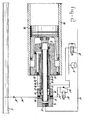
- Figure 2 is an axial section of another form of construction of the piston-plunger assembly shown in figure 1,
- Figure 3 shows schematically another possible form of construction of the apparatus according to the invention, and
- Figure 4 is an axial section of a valve member used in an apparatus according to the invention.
- As shown in figure 1, the apparatus comprises in this case a variable hydraulic motor 1, which is connected via the
pipe 2 to an accumulator 3 for pressurized liquid and which has an outlet 4 for this liquid, leading to areservoir 5 which may optionally be under a low superatmospheric pressure. - In addition, a free-piston unit is provided which consists of a cylinder 6 containing two
free pistons 7 and 7' which are reciprocatingly slidable therein and which during the compression stroke move towards one another and during the expansion stroke move away from one another, said free pistons together delimiting aspace 8 inside the cylinder 6. This space is for example in the form of a combustion chamber, the wall of the cylinder 6 being in that case provided with inlet and outlet ports (not shown), while means (not shown) for injecting as fuel into thecombustion chamber 8 are provided, so that the combustion of said fuel takes place in accordance with the two-stroke diesel principle. - The
pistons 7 and 7' are substantially identical, so that only thepiston 7 will be further described, the same reference numerals with the addition of a prime being used to designate corresponding parts of the piston 7'. - The
piston 7 is connected to a plunger-shaped member 9, which comprises afirst part 10 adapted to slide reciprocatingly inside achamber member 11, the outer peripheral surface of saidpart 10 making a sliding fit with the inside wall of thechamber member 11, so that theend surface 12 of saidpart 10 delimits inside the member 11 aplunger space 13 which is in communication with the accumulator 3 via apipe 14 and avalve system 26. The plunger-shaped member 9 has asecond part 15, the outer peripheral surface of which makes a sliding fit with the inside surface of asecond chamber member 16 and which has a firstannular end face 17 which delimits adisplacement chamber 18 inside thechamber member 16. Thisdisplacement chamber 18 is in communication via apipe 19, provided with a nonreturn valve 20, with theliquid reservoir 5, and via apipe 21, provided with anonreturn valve 22, with the accumulator 3. Thesecond part 15 of the plunger-shaped member 9 also has a secondannular end face 23, which is directed oppositely to theend face 17 and which delimits abuffer chamber 24 inside thesecond chamber member 16. Thisbuffer chamber 24 is in communication via aline 25 not only with the accumulator but also via thevalve displacement chamber 18. - The
pipes 14, 14' contain anoperable valve member 26, so that on the opening of this valve, which takes place after the pressure in the accumulator 3 has fallen below a specific minimum level, theplunger chambers 13, 13' are brought into open communication with the accumulator 3, whereby because of the liquid pressure acting on thefaces 12, 12' thepistons 7, 7' are driven towards one another for the performance of the compression stroke, the gas pressure in thechamber 8 thus rising. At the same time liquid is also drawn out of thereservoir 5, via thepipes 19, 19' and valves 20, 20', into thedisplacement chambers 18, 18'. After thepiston 7, 7' have reached a determined position, fuel is injected into thechamber 8, the burning of which is initiated by selfignition combustion, so that the gas pressure in thechamber 8 rises sharply, with the consequence that the pistons are moved away from on another for the performance of the expansion stroke. During this expansion stroke, liquid present in theplunger chambers 13, 13' and liquid from thechambers 18, 18' are displaced viarespective pipes pipes 25, 25' to thebuffer chambers 24, 24'. As the end of the expansion stroke approaches, thevalve 26 is closed again. At the end of the expansion stroke the movements of the pistons are reversed because of the compressibility of the liquid still present in thechambers pistons 7, 7' are braked by the liquid pressure acting on thesurfaces 23, 23' of thebuffer chambers 24, 24'. In order then to prevent the occurence of cavitation in thechambers 13, 13', thepipes 14, 14' are connected via thepipe 27, containing thenonreturn valve 28, to the liquid reservoir 3, so that liquid can be drawn via thepipes plunger chambers 13, 13'. - In order to ensure good operation of the free-piston motor it is of great importance that after each expansion stroke the starting positions of the
pistons 7, 7' should lie within close tolerance limits. To enable these starting positions to be corrected during the waiting time after an expansion stroke, theoperable valve members 29, 29' are provided. By opening one or both of these valve members, therespective piston 7, 7' can be slightly displaced in the direction of the other piston in view of the fact that thedisplacement chamber 18, 18' is thereby brought into open communication with the accumulator 3, so that the liquid pressure prevailing in the accumulator 3 acts on thesurface 17, 17' which has a larger working area than thesurface 23, 23' of thebuffer chamber 24, 24'. - In addition, the
displacement chambers 18, 18' can be brought into open communication with theliquid reservoir 5 via thepipes 30, 30' through the opening of thevalve members 31, while theplunger chambers 13, 13' can be similarly brought into open communication with theliquid reservoir 5 via thepipes valve member 32, so that because of the liquid pressure acting on thesurfaces 23, 23' of thebuffer chambers 24, 24' both thepistons 7, 7' can be brought into the correct outer starting position, which is of particular importance when the free-piston motor is started up after a long stoppage. - Furthermore, an
adjustable constriction 33 is provided, by means of which the speed at which thepistons 7, 7' are brought to the outer starting positions can be adjusted. Moreover, when a cold motor has to be started, this constriction can be used to control the pressure in thedisplacement chambers 18, 18', in which case only thevalve member 31 is operated. This is necessary in order to maintain a constant stroke of thefree piston 7, 7' despite higher viscosity and lower combustion efficiency. - In addition, a
pump 34 is provided, with the aid of which the hydraulic system can be pressurized after a long stoppage. - For the cooling of the combustion chamber 8 a cooling
coil 71 is disposed around the cylinder 6 and is covered by ajacket 72 of insulating material. Thecoil 71 is in communication at one end, via thepipe 73, with the outlet 4 of the hydraulic motor 1, and at the other end, via thepipe 74, with a cooler 75, and also, via the pipe 76, with thereservoir 5. In this way thecombustion chamber 8 can thus be cooled with the aid of return oil from the hydraulic system. - In order to increase the cooling capacity of the cooler 75 under extreme conditions a
fan 77 is provided, which is driven by thehydraulic motor 78, the latter being in communication with the accumulator 3 via thepipe 79 and thevalve 80 contained in it. - In order to be able to cool the
chamber 8 when the hydraulic motor 1 is at rest, so that there is no return oil flow, thevalve 81 can be operated to enable cooled oil to be pumped from thereservoir 5 through thecoil 71 by means of thepump 34. - Half of a form of construction of the free-piston unit according to the invention, of the type shown in figure 1, is shown in longitudinal section in figure 2. A
free piston 36 is reciprocatingly slidable in thecylinder 35. Thefree piston 36 is connected to a tube 37 which is closed at the piston end and at the other end is provided with a radial thickening 38. Asecond tube 39 mounted in a fixedblock 44 extends inside the tube 37, the inner periphery of the thickening 38 on the tube 37 making a sliding fit with the outer periphery of thetube 39, so that thetubes 37 and 39 form together aplunger chamber 40 which at 41 is in communication, via thepipe 14" and the operable valve member 32', with the accumulator 3', and which at the other end is bounded by thesurface 42, of which the part delimited by the outside diameter of thetube 39 coincides with thesurface 12 in figure 1. A bush-shapedmember 43 is mounted at its one end in the fixedblock 44 and at the other end in a body 45 connected to the wall of thecylinder 35. The bush-shapedmember 43 is disposed coaxially around thetubes 37 and 39 in such a manner that the outer peripheral surface of the radial thickening 38 makes a sliding fit with the inside wall of the bush-shapedmember 43, so that on one side of the thickening 38 an annular displacement chamber 46 having an operative surface 47 is formed, while on the other side of the thickening 38 abuffer chamber 48 having anoperative surface 49 is formed. The displacement chamber 46 is in communication via the connection 50 with thepipe 19" leading to the liquid reservoir 5' and containing the nonreturn valve 20', and via theconnection 51 to thepipe 21" leading to the accumulator 3' and containing thenonreturn valve 22". Thebuffer chamber 48 is in communication with thepipe 25" via the connection 52. - The embodiment shown in figure 2 has a compact construction and high efficiency. This high efficiency is achieved, inter alia, through the elastic deformation of the wall of the
tube 39 during the compression stroke, whereby the clearance and consequently the leakage between themembers 38 and 39 will be reduced. - During the expansion stroke there is no pressure differential over the
tube 39, so that there is a greater clearance between 38 and 39 and therefore lower losses due to friction. Moreover, in this embodiment the surfaces which are difficult to machine are relatively small, so that production costs are lower. - Figure 3 shows schematically a second form of construction of the apparatus according to the invention in which only the free-pistonunit is shown.
- This second form of construction differs from the first form substantially only in that the
valve 26 in figure 1 is replaced by twovalves single valves valves valves 86, 87 respectively. - The free-pistonunit comprises a
cylinder 88 containing two free-pistons 89 and 89' which are recip- . rocatingly slidable therein. Eachpiston 89, 89' is connected to a plunger-shapedmember 90, 90' which comprises afirst part 91, 91' which with its end surface delimits inside achamber member 92, 92' a plunger-space 93, 93'. Said plunger-shapedmember 90, 90' has a second part 94, 94' which delimits inside thechamber element 95, 95' at the one side adisplacement chamber 96, 96' and at the other side a buffer chamber 97, 97'. Saiddisplacement chamber 96, 96' is in communication via apipe 98, 98' provided with anonreturn valve 99, 99', with theliquid reservoir 100, and via apipe 101, 101', provided with anonreturn valve 102, 102' with theaccumulator 103, whereas the buffer chamber 97, 97' is in communication via aline 104, 104' not only with theaccumulator 103 but also via thevalve 102 with thedisplacement chamber 96, 96'. - Each plunger-
chamber 93, 93' is in communication with theaccumulator 103 via an own separateoperable valve member pistons 89, 89' in their outermost positions inside thecylinder 88 can be corrected by opening one of thevalve members piston 89, 89' situated most to the outside insidecylinder 88 is iniated in advance of the compression stroke of the other piston. Thus thevalve members 29, 29' which are provided for this correction purpose in figure 1 are disposed off in the second embodiment. - Further the
liquid chambers 69, 69' can be brought into open communication with thereservoir 100 through pipe 105,105' by opening thevalve members plunger chambers 93, 93' can be brought into open communication with theliquid reservoir 100 by opening thevalve members 86, 87 respectively, sothat because of the liquid pressure acting on the surfaces of the plunger shaped element which delimits the buffer chambers 97, 97', bothpistons 89 89' can be brought into the correct outer starting position. - Furthermore an adjustable constriction 84', 85' is provided, by means of which the speed at which the pistons are brought to the outer starting positions can be adjusted.
- The second embodiment offers the advantage with respect to the first embodiment that each side of the free-piston unit requires only one intake and one outlet conduit so that the reliability of the apparatus is increased and the risk of failures is decreased. Furthermore a reduction of waiting time after each cycle is obtained, resulting in an increased top power output.
- Figure 4 shows an axial section of a form of construction of an operable valve member according to the invention, this form of construction being particularly suitable for the
operable valves - The valve member comprises a
body 53 which is tightly enclosed in the partially shown jacket 53'. The body hasconnections connections 54 merges into apassage 56, which in turn merges into a chamber 56'. Abore 57 and a plurality of bores 58 and a plurality ofbores 59 open into the chamber 56'. - The bores 58 bring the chamber 56' into open communication with the
annular chamber 60, so that the high pressure prevails in saidchamber 60. - The
bores 59 also open into thechamber 60, while at this outlet point a valve seat is formed, onto which a preferablyspherical valve body 61 is pressed by means of thespring 62, the high pressure insidechamber 60 acting on the top face ofvalve body 61 which faces away from said valve seat. - in addition, each bore 59 is in communication with a
passage 63 which is in communication with theconnection 55 on the low pressure side so that the low pressure acts on the bottom face ofvalve body 61. A pin-shaped member 64 is arranged to slide in each bore 59 and has ashoulder surface 65 which is directed towards theconnection 54 and which delimits inside the bore 59 a chamber which is in communication with thespace 69 via thepassage 66, the annular space 67, and the transverse passage 68. - The
bore 57, in which one or more (in the present case two) preloaded nonreturn valves are disposed, also leads out into the annular space 67, so that the space under theshoulder 65, thepassage 66, the annular space 67, the passage 68 and thespace 69 will always be filled with liquid under high pressure. In thebody 53 at least one actuator, in the embodiment shown specifically a piezoelectric element 70 is disposed which drives a membrane- or plunger-shaped body 70', so that when a voltage is applied to an element of this kind a displacement of great power but short stroke is produced, which is converted by means of the hydrostatic transmission into a larger displacement of the pin-shaped member 64, whereby thespherical valve member 61 is lifted off its seat. This results in the establishment of communication between theannular space 60 and thepassage 63, which means that the liquid can flow from theconnection 54 through thepassage 56, the chamber 56', the bores 58, theannular chamber 60, and thepassage 63 to theconnection 55. If in the closed situation the pressure at theconnection 55 rises above the pressure at theconnection 54, theballs 61 will be lifted off because of the pressure differential over these balls, and the liquid will flow from theconnection 55, via thespace 60, the bores 58, the chamber 56', and thepassage 56 to theconnection 54. In addition to its on-off function for a flow of liquid from theconnection 54 to theconnection 55, the valve thus has also a non- return function for an oppositely directed flow, so that with a single valve it is possible to replace an on-off valve and a non-return valve mounted in a bypass, as shown in figure 1, for example, at 29, 22; 26 and in figure 3 at 82, 83 and 86, 87.
Claims (15)
Priority Applications (1)
| Application Number | Priority Date | Filing Date | Title |
|---|---|---|---|
| AT87201312T ATE57990T1 (en) | 1986-07-25 | 1987-07-09 | FREE PISTON ENGINE WITH HYDRAULIC OR PNEUMATIC TRANSMISSION. |
Applications Claiming Priority (2)
| Application Number | Priority Date | Filing Date | Title |
|---|---|---|---|
| NL8601931 | 1986-07-25 | ||
| NL8601931A NL8601931A (en) | 1986-07-25 | 1986-07-25 | FREE-PISTON MOTOR WITH HYDRAULIC OR PNEUMATIC ENERGY TRANSFER. |
Publications (2)
| Publication Number | Publication Date |
|---|---|
| EP0254353A1 EP0254353A1 (en) | 1988-01-27 |
| EP0254353B1 true EP0254353B1 (en) | 1990-10-31 |
Family
ID=19848352
Family Applications (1)
| Application Number | Title | Priority Date | Filing Date |
|---|---|---|---|
| EP87201312A Expired - Lifetime EP0254353B1 (en) | 1986-07-25 | 1987-07-09 | Free-piston motor with hydraulic or pneumatic energy transmission |
Country Status (11)
| Country | Link |
|---|---|
| US (1) | US4791786A (en) |
| EP (1) | EP0254353B1 (en) |
| JP (1) | JPH0674751B2 (en) |
| KR (1) | KR950003745B1 (en) |
| CN (1) | CN1011998B (en) |
| AT (1) | ATE57990T1 (en) |
| CA (1) | CA1293197C (en) |
| DE (1) | DE3765868D1 (en) |
| ES (1) | ES2019371B3 (en) |
| GR (1) | GR3001040T3 (en) |
| NL (1) | NL8601931A (en) |
Families Citing this family (23)
| Publication number | Priority date | Publication date | Assignee | Title |
|---|---|---|---|---|
| US5036667A (en) * | 1990-05-09 | 1991-08-06 | Thatcher Eric A | Fluid power engine |
| FI85748C (en) * | 1990-10-19 | 1992-05-25 | Sampower Oy | FOERFARANDE OCH ANORDNING FOER ATT HYDRAULISKT STARTA EN FRIKOLVSMOTOR. |
| HU216128B (en) * | 1991-02-14 | 1999-07-28 | Gábor Pál Sztelek | Internal combustion engine |
| NL9101931A (en) * | 1991-11-19 | 1993-06-16 | Innas Bv | FREE-PISTON MOTOR WITH HYDRAULIC AGGREGATE. |
| NL1001939C2 (en) * | 1995-04-10 | 1996-10-11 | Potma Beheer B V T | Device for generating fast movement for controlling free piston aggregate in particular |
| US5934245A (en) * | 1997-11-19 | 1999-08-10 | Caterpillar Inc. | Two cycle engine having a mono-valve integrated with a fuel injector |
| US6076506A (en) * | 1998-05-20 | 2000-06-20 | Caterpillar Inc. | Piston for use in an engine |
| US6152091A (en) * | 1999-02-22 | 2000-11-28 | Caterpillar Inc. | Method of operating a free piston internal combustion engine with a variable pressure hydraulic fluid output |
| US6269783B1 (en) | 1999-02-22 | 2001-08-07 | Caterpillar Inc. | Free piston internal combustion engine with pulse compression |
| US6206656B1 (en) | 1999-02-22 | 2001-03-27 | Caterpillar Inc. | Method of operating a free piston internal combustion engine with high pressure hydraulic fluid upon misfire or initial start-up |
| US6158401A (en) * | 1999-02-24 | 2000-12-12 | Caterpillar Inc. | Method of operating a free piston internal combustion engine with pulse compression |
| US6293231B1 (en) | 1999-09-29 | 2001-09-25 | Ingo Valentin | Free-piston internal combustion engine |
| DE10120196A1 (en) * | 2000-05-19 | 2001-11-22 | Mannesmann Rexroth Ag | Free piston engine has engine piston driven by staged hydraulic piston, section of which with lesser diameter is arranged in work cylinder and section with greater diameter in compression cylinder |
| US6959545B2 (en) * | 2004-02-01 | 2005-11-01 | Ford Global Technologies, Llc | Engine control based on flow rate and pressure for hydraulic hybrid vehicle |
| EP2044305A4 (en) * | 2006-07-26 | 2010-11-17 | J Michael Langham | WATER ENGINE |
| CN101532427B (en) * | 2008-03-15 | 2013-04-03 | 熊艳 | Four-stroke hydraulic engine without crank link mechanism |
| CN101539132B (en) * | 2009-04-21 | 2012-07-04 | 西安交通大学 | Linear transmission mechanism of reciprocating dynamic machinery |
| JP5630123B2 (en) * | 2010-07-28 | 2014-11-26 | 株式会社豊田中央研究所 | Linear power generation free piston engine and starting method thereof |
| CN104632165B (en) * | 2014-12-23 | 2017-02-22 | 中国石油天然气股份有限公司 | A system for increasing production of low-pressure wells by using adjacent high-pressure wells |
| RU2641997C1 (en) * | 2017-04-28 | 2018-01-23 | Анатолий Александрович Рыбаков | Method of pneumatic drive of two-valved gas distributor of a free piston power module with a generic external combustion chamber |
| CL2020002789A1 (en) * | 2020-10-27 | 2021-03-26 | Ernesto Gutzlaff Lillo Luis | Three-stroke internal combustion engine with hydraulic motion transmission |
| JP2023548559A (en) | 2020-11-05 | 2023-11-17 | メインスプリング エナジー, インコーポレイテッド | Core synchronization for linear generators |
| CN114893293B (en) * | 2022-06-21 | 2023-03-21 | 北京理工大学 | Electromechanical-hydraulic-cooling coupled free piston engine integrated system and operation method |
Family Cites Families (9)
| Publication number | Priority date | Publication date | Assignee | Title |
|---|---|---|---|---|
| FR398207A (en) * | 1908-01-10 | 1909-05-29 | Dagobert Timar | Machine for the extraction of gases or liquids |
| FR913415A (en) * | 1944-09-15 | 1946-09-10 | Sulzer Ag | Method and device for cooling a piston by air or gas |
| US2978986A (en) * | 1956-09-28 | 1961-04-11 | American Mach & Foundry | Free piston engine |
| ZA714717B (en) * | 1970-08-24 | 1973-02-28 | A Braun | Free piston engine starting apparatus and method |
| FR2212486A1 (en) * | 1972-12-29 | 1974-07-26 | Sigaud Pierre | |
| US4307999A (en) * | 1979-06-25 | 1981-12-29 | Pneumo Corporation | Free piston engine pump including variable energy rate and acceleration-deceleration controls |
| US4308720A (en) * | 1979-11-13 | 1982-01-05 | Pneumo Corporation | Linear engine/hydraulic pump |
| FR2488344B1 (en) * | 1980-08-05 | 1985-12-27 | Renault | HYDRAULIC GENERATOR WITH FREE PISTON MOTOR |
| US4382748A (en) * | 1980-11-03 | 1983-05-10 | Pneumo Corporation | Opposed piston type free piston engine pump unit |
-
1986
- 1986-07-25 NL NL8601931A patent/NL8601931A/en not_active Application Discontinuation
-
1987
- 1987-07-09 AT AT87201312T patent/ATE57990T1/en not_active IP Right Cessation
- 1987-07-09 EP EP87201312A patent/EP0254353B1/en not_active Expired - Lifetime
- 1987-07-09 ES ES87201312T patent/ES2019371B3/en not_active Expired - Lifetime
- 1987-07-09 DE DE8787201312T patent/DE3765868D1/en not_active Expired - Lifetime
- 1987-07-14 CA CA000542027A patent/CA1293197C/en not_active Expired - Lifetime
- 1987-07-20 US US07/075,618 patent/US4791786A/en not_active Expired - Lifetime
- 1987-07-24 KR KR1019870008053A patent/KR950003745B1/en not_active Expired - Fee Related
- 1987-07-24 JP JP62186483A patent/JPH0674751B2/en not_active Expired - Lifetime
- 1987-07-25 CN CN87105140A patent/CN1011998B/en not_active Expired
-
1990
- 1990-11-01 GR GR90400859T patent/GR3001040T3/en unknown
Also Published As
| Publication number | Publication date |
|---|---|
| CN87105140A (en) | 1988-03-02 |
| KR950003745B1 (en) | 1995-04-18 |
| KR880001938A (en) | 1988-04-28 |
| JPH0674751B2 (en) | 1994-09-21 |
| NL8601931A (en) | 1988-02-16 |
| ATE57990T1 (en) | 1990-11-15 |
| CA1293197C (en) | 1991-12-17 |
| GR3001040T3 (en) | 1992-01-20 |
| JPS63100229A (en) | 1988-05-02 |
| CN1011998B (en) | 1991-03-13 |
| EP0254353A1 (en) | 1988-01-27 |
| DE3765868D1 (en) | 1990-12-06 |
| ES2019371B3 (en) | 1991-06-16 |
| US4791786A (en) | 1988-12-20 |
Similar Documents
| Publication | Publication Date | Title |
|---|---|---|
| US4791786A (en) | Free-piston motor with hydraulic or pneumatic energy transmission | |
| US4469055A (en) | Controlled variable compression ratio piston for an internal combustion engine | |
| KR100595778B1 (en) | Devices for changing their effective volume displacement or volume ratio during operation of piston engines | |
| US4599861A (en) | Internal combustion hydraulic engine | |
| AU644691B2 (en) | Method and apparatus for starting a displacer engine hydraulically | |
| US4347701A (en) | Power system for land vehicles | |
| US2661695A (en) | Reduction of noise and shock in power pumps | |
| CN104929766B (en) | Hydraulic free piston engine | |
| GB1581168A (en) | Stirling engine power control apparatus | |
| US2083680A (en) | Internal combustion engine | |
| WO2019090388A1 (en) | Pumping systems | |
| US4500262A (en) | Variable pressure and displacement reciprocating pump | |
| US3839858A (en) | Reciprocating machine | |
| US3024591A (en) | Bounce compensator for free piston engines | |
| WO1986001562A1 (en) | Controlled variable compression ratio piston for an internal combustion engine | |
| US3838941A (en) | Pumping unit | |
| US4494514A (en) | Hydraulic adjusting device for controlling the beginning of injection of an injection pump | |
| EP0100149A1 (en) | Diaphragm pumps | |
| US4568251A (en) | Cyclic speed control apparatus in variable stroke machines | |
| US5314315A (en) | Hydraulic pump output pressure compensation system | |
| US3730652A (en) | Fluid pressure devices | |
| US3138918A (en) | Fluid engine having a pressurized crankcase | |
| KR100394540B1 (en) | Switching Valves for Reversible Hydraulic Drives and Reversible Hydraulic Drives | |
| US3199456A (en) | Vehicle and control system therefor | |
| US3851667A (en) | Pulsator for hydraulic systems controlling actuating mechanisms |
Legal Events
| Date | Code | Title | Description |
|---|---|---|---|
| PUAI | Public reference made under article 153(3) epc to a published international application that has entered the european phase |
Free format text: ORIGINAL CODE: 0009012 |
|
| AK | Designated contracting states |
Kind code of ref document: A1 Designated state(s): AT BE CH DE ES FR GB GR IT LI LU NL SE |
|
| 17P | Request for examination filed |
Effective date: 19880718 |
|
| 17Q | First examination report despatched |
Effective date: 19891010 |
|
| GRAA | (expected) grant |
Free format text: ORIGINAL CODE: 0009210 |
|
| AK | Designated contracting states |
Kind code of ref document: B1 Designated state(s): AT BE CH DE ES FR GB GR IT LI LU NL SE |
|
| REF | Corresponds to: |
Ref document number: 57990 Country of ref document: AT Date of ref document: 19901115 Kind code of ref document: T |
|
| REF | Corresponds to: |
Ref document number: 3765868 Country of ref document: DE Date of ref document: 19901206 |
|
| ET | Fr: translation filed | ||
| ITF | It: translation for a ep patent filed | ||
| REG | Reference to a national code |
Ref country code: GR Ref legal event code: FG4A Free format text: 3001040 |
|
| ITTA | It: last paid annual fee | ||
| PLBE | No opposition filed within time limit |
Free format text: ORIGINAL CODE: 0009261 |
|
| STAA | Information on the status of an ep patent application or granted ep patent |
Free format text: STATUS: NO OPPOSITION FILED WITHIN TIME LIMIT |
|
| 26N | No opposition filed | ||
| REG | Reference to a national code |
Ref country code: GB Ref legal event code: 732 |
|
| ITPR | It: changes in ownership of a european patent |
Owner name: CESSIONE;ADVANCED POWER SYSTEMS B.V. |
|
| REG | Reference to a national code |
Ref country code: CH Ref legal event code: PUE Owner name: ADVANCED POWER SYSTEMS B.V. |
|
| NLS | Nl: assignments of ep-patents |
Owner name: ADVANCED POWER SYSTEMS B.V. TE ROTTERDAM. |
|
| REG | Reference to a national code |
Ref country code: ES Ref legal event code: PC2A Owner name: ADVANCED POWER SYSTEMS B.V. |
|
| EPTA | Lu: last paid annual fee | ||
| EAL | Se: european patent in force in sweden |
Ref document number: 87201312.3 |
|
| PGFP | Annual fee paid to national office [announced via postgrant information from national office to epo] |
Ref country code: ES Payment date: 19970131 Year of fee payment: 10 |
|
| PG25 | Lapsed in a contracting state [announced via postgrant information from national office to epo] |
Ref country code: ES Free format text: LAPSE BECAUSE OF NON-PAYMENT OF DUE FEES Effective date: 19970710 |
|
| PGFP | Annual fee paid to national office [announced via postgrant information from national office to epo] |
Ref country code: GR Payment date: 20000630 Year of fee payment: 14 |
|
| PGFP | Annual fee paid to national office [announced via postgrant information from national office to epo] |
Ref country code: SE Payment date: 20000705 Year of fee payment: 14 Ref country code: GB Payment date: 20000705 Year of fee payment: 14 |
|
| PGFP | Annual fee paid to national office [announced via postgrant information from national office to epo] |
Ref country code: LU Payment date: 20000710 Year of fee payment: 14 Ref country code: DE Payment date: 20000710 Year of fee payment: 14 |
|
| PGFP | Annual fee paid to national office [announced via postgrant information from national office to epo] |
Ref country code: FR Payment date: 20000711 Year of fee payment: 14 |
|
| PGFP | Annual fee paid to national office [announced via postgrant information from national office to epo] |
Ref country code: CH Payment date: 20000712 Year of fee payment: 14 Ref country code: AT Payment date: 20000712 Year of fee payment: 14 |
|
| PGFP | Annual fee paid to national office [announced via postgrant information from national office to epo] |
Ref country code: NL Payment date: 20000731 Year of fee payment: 14 |
|
| PGFP | Annual fee paid to national office [announced via postgrant information from national office to epo] |
Ref country code: BE Payment date: 20000918 Year of fee payment: 14 |
|
| PG25 | Lapsed in a contracting state [announced via postgrant information from national office to epo] |
Ref country code: LU Free format text: LAPSE BECAUSE OF NON-PAYMENT OF DUE FEES Effective date: 20010709 Ref country code: GB Free format text: LAPSE BECAUSE OF NON-PAYMENT OF DUE FEES Effective date: 20010709 Ref country code: AT Free format text: LAPSE BECAUSE OF NON-PAYMENT OF DUE FEES Effective date: 20010709 |
|
| PG25 | Lapsed in a contracting state [announced via postgrant information from national office to epo] |
Ref country code: SE Free format text: LAPSE BECAUSE OF NON-PAYMENT OF DUE FEES Effective date: 20010710 |
|
| PG25 | Lapsed in a contracting state [announced via postgrant information from national office to epo] |
Ref country code: LI Free format text: LAPSE BECAUSE OF NON-PAYMENT OF DUE FEES Effective date: 20010731 Ref country code: GR Free format text: LAPSE BECAUSE OF NON-PAYMENT OF DUE FEES Effective date: 20010731 Ref country code: CH Free format text: LAPSE BECAUSE OF NON-PAYMENT OF DUE FEES Effective date: 20010731 Ref country code: BE Free format text: LAPSE BECAUSE OF NON-PAYMENT OF DUE FEES Effective date: 20010731 |
|
| BERE | Be: lapsed |
Owner name: ADVANCED POWER SYSTEM B.V. Effective date: 20010731 |
|
| PG25 | Lapsed in a contracting state [announced via postgrant information from national office to epo] |
Ref country code: NL Free format text: LAPSE BECAUSE OF NON-PAYMENT OF DUE FEES Effective date: 20020201 |
|
| GBPC | Gb: european patent ceased through non-payment of renewal fee |
Effective date: 20010709 |
|
| EUG | Se: european patent has lapsed |
Ref document number: 87201312.3 |
|
| REG | Reference to a national code |
Ref country code: CH Ref legal event code: PL |
|
| PG25 | Lapsed in a contracting state [announced via postgrant information from national office to epo] |
Ref country code: FR Free format text: LAPSE BECAUSE OF NON-PAYMENT OF DUE FEES Effective date: 20020329 |
|
| NLV4 | Nl: lapsed or anulled due to non-payment of the annual fee |
Effective date: 20020201 |
|
| PG25 | Lapsed in a contracting state [announced via postgrant information from national office to epo] |
Ref country code: DE Free format text: LAPSE BECAUSE OF NON-PAYMENT OF DUE FEES Effective date: 20020501 |
|
| REG | Reference to a national code |
Ref country code: FR Ref legal event code: ST |
|
| REG | Reference to a national code |
Ref country code: ES Ref legal event code: FD2A Effective date: 19980811 |
|
| PG25 | Lapsed in a contracting state [announced via postgrant information from national office to epo] |
Ref country code: IT Free format text: LAPSE BECAUSE OF NON-PAYMENT OF DUE FEES;WARNING: LAPSES OF ITALIAN PATENTS WITH EFFECTIVE DATE BEFORE 2007 MAY HAVE OCCURRED AT ANY TIME BEFORE 2007. THE CORRECT EFFECTIVE DATE MAY BE DIFFERENT FROM THE ONE RECORDED. Effective date: 20050709 |