EP0253796A2 - Anatomical bone plate or fixation plate - Google Patents
Anatomical bone plate or fixation plate Download PDFInfo
- Publication number
- EP0253796A2 EP0253796A2 EP87890155A EP87890155A EP0253796A2 EP 0253796 A2 EP0253796 A2 EP 0253796A2 EP 87890155 A EP87890155 A EP 87890155A EP 87890155 A EP87890155 A EP 87890155A EP 0253796 A2 EP0253796 A2 EP 0253796A2
- Authority
- EP
- European Patent Office
- Prior art keywords
- plate
- fragment
- socket
- section
- plate according
- Prior art date
- Legal status (The legal status is an assumption and is not a legal conclusion. Google has not performed a legal analysis and makes no representation as to the accuracy of the status listed.)
- Granted
Links
Images


Classifications
-
- A—HUMAN NECESSITIES
- A61—MEDICAL OR VETERINARY SCIENCE; HYGIENE
- A61B—DIAGNOSIS; SURGERY; IDENTIFICATION
- A61B17/00—Surgical instruments, devices or methods, e.g. tourniquets
- A61B17/56—Surgical instruments or methods for treatment of bones or joints; Devices specially adapted therefor
- A61B17/58—Surgical instruments or methods for treatment of bones or joints; Devices specially adapted therefor for osteosynthesis, e.g. bone plates, screws, setting implements or the like
- A61B17/68—Internal fixation devices, including fasteners and spinal fixators, even if a part thereof projects from the skin
- A61B17/80—Cortical plates, i.e. bone plates; Instruments for holding or positioning cortical plates, or for compressing bones attached to cortical plates
- A61B17/8061—Cortical plates, i.e. bone plates; Instruments for holding or positioning cortical plates, or for compressing bones attached to cortical plates specially adapted for particular bones
- A61B17/8066—Cortical plates, i.e. bone plates; Instruments for holding or positioning cortical plates, or for compressing bones attached to cortical plates specially adapted for particular bones for pelvic reconstruction
-
- A—HUMAN NECESSITIES
- A61—MEDICAL OR VETERINARY SCIENCE; HYGIENE
- A61B—DIAGNOSIS; SURGERY; IDENTIFICATION
- A61B17/00—Surgical instruments, devices or methods, e.g. tourniquets
- A61B17/56—Surgical instruments or methods for treatment of bones or joints; Devices specially adapted therefor
- A61B17/58—Surgical instruments or methods for treatment of bones or joints; Devices specially adapted therefor for osteosynthesis, e.g. bone plates, screws, setting implements or the like
- A61B17/68—Internal fixation devices, including fasteners and spinal fixators, even if a part thereof projects from the skin
- A61B17/80—Cortical plates, i.e. bone plates; Instruments for holding or positioning cortical plates, or for compressing bones attached to cortical plates
- A61B17/8095—Wedge osteotomy devices
-
- A—HUMAN NECESSITIES
- A61—MEDICAL OR VETERINARY SCIENCE; HYGIENE
- A61B—DIAGNOSIS; SURGERY; IDENTIFICATION
- A61B17/00—Surgical instruments, devices or methods, e.g. tourniquets
- A61B17/56—Surgical instruments or methods for treatment of bones or joints; Devices specially adapted therefor
- A61B17/58—Surgical instruments or methods for treatment of bones or joints; Devices specially adapted therefor for osteosynthesis, e.g. bone plates, screws, setting implements or the like
- A61B17/68—Internal fixation devices, including fasteners and spinal fixators, even if a part thereof projects from the skin
- A61B17/82—Internal fixation devices, including fasteners and spinal fixators, even if a part thereof projects from the skin for bone cerclage
-
- Y—GENERAL TAGGING OF NEW TECHNOLOGICAL DEVELOPMENTS; GENERAL TAGGING OF CROSS-SECTIONAL TECHNOLOGIES SPANNING OVER SEVERAL SECTIONS OF THE IPC; TECHNICAL SUBJECTS COVERED BY FORMER USPC CROSS-REFERENCE ART COLLECTIONS [XRACs] AND DIGESTS
- Y10—TECHNICAL SUBJECTS COVERED BY FORMER USPC
- Y10S—TECHNICAL SUBJECTS COVERED BY FORMER USPC CROSS-REFERENCE ART COLLECTIONS [XRACs] AND DIGESTS
- Y10S606/00—Surgery
- Y10S606/902—Cortical plate specifically adapted for a particular bone
Definitions
- the invention relates to a bone fixation plate for screw fixation of the socket fragment on the ilium after pelvic osteotomies with tilting of the roof of the socket, in particular in humans, in which the socket in the region of the ilium and ischium with an optionally joint cut, in particular with an incision made essentially along a cylinder jacket, and in Area of the pubic bone was separated with a separate, in particular flat, incision, the stable fixation of this plate taking place on the facies glutaea of the cranial pelvic pillar of the iliac scoop.
- the pubic bone osteotomy is then performed close to the hip joint. It is placed approximately parallel to the body axis in a slightly oblique direction in the obturate foramen in order to ensure that bone contact is retained after the acetabular roof has been swiveled in order to enable rapid subsequent bone development.
- the third stage is the iliac osteotomy.
- a Steinmann nail is injected into the pelvic bones as a later aid when twisting and swiveling the pan, parallel to the planned osteotomy, which descends medially.
- the iliac osteotomy is done in one plane, first with the oscillating saw, then with chisels.
- the pan is then turned and swiveled over the femoral head; at least to the extent that the femoral head had to be spread out beforehand, to get under the pan roof.
- the socket on the Steinmann nail is pulled over the femoral head and, if necessary, also forward, and the medial pubic branch is pushed upwards in the sense of rotation. Then the pan is medialized by hand pressure and good contact is made with the pubic bone.
- the pan can be fixed stably to the facies glutaea of the cranial pelvic pillar of the iliac vein via a specially designed plate, i.e. is no longer dependent on the use of Kirschner wires and the removal of wedges from the iliac scoop or the interposition of bone wedges.
- This anatomical bone plate according to the invention is primarily characterized in that the plate has a proximal section for, in particular at least essentially form-fitting, contact with the iliac scoop and a distal section for, in particular at least essentially positive-fitting, contact with the pan fragment, the sections in stand at an angle to one another which is in the range from 10 to 50 °, preferably at approximately 30 °, and wherein an essentially wedge-shaped transition zone is formed between the sections, the greatest width of which is preferably located on the ventral edge of the plate.
- This anatomical fixation plate is screwed to the iliac scoop and the socket fragment and, in one embodiment, supports with its transition zone the osteotomy edge of the socket fragment, which protrudes proximally due to the displacement of the socket fragment, in particular the swiveling to the ventral and the tilting laterally, over the outer surface of the iliac scoop. ie compared to the pressure on the leg.
- DE-AS 24 10 057 has disclosed a bone plate which can be attached in the socket area.
- the known plate is fixed on the ilium by two proximal tabs, between which a recess is provided for receiving the base of the iliac crest; the plate rests on the acetabular roof and its distally distally bent edge forms the acetabular roof edge, in other words the proximal area of the socket - the acetabular roof - is artificially widened predominantly laterally in order to prevent proximal luxation of the femoral head.
- the purpose of this known plate and consequently also its geometric design is completely different from that of the plate according to the invention.
- anatomical bone plate When using the anatomical bone plate according to the invention, in particular a stable fixation by compression osteosynthesis between the socket fragment and the iliac scoop and an early resilience of the hip joint and the extremity can be achieved, so it is a primarily load and exercise stable fixation. The result is rapid postoperative patient mobilization.
- the stable fixation of the plate to the iliac vein advantageously takes place in such a way that the optimal pressure absorption area in the iliac vein is recorded with reference to the O position of the femur, i.e. at the anterior part of the ala ossis ilii, just distal to the gluteal tubercle, beginning approximately one finger width dorsally of the anterior superior iliac spine and the Anterior inferior iliac spine and approximately to the anterior gluteal line, particularly in the ventral area between the supporting parts of the cranial and caudal pelvic pillars.
- a major advantage is obtained if the iliac osteotomy required for pivoting the acetabular roof is not carried out as a flat cut as before, so that after the pan fragment has been pivoted ventrally and laterally, the osteotomy surfaces between the pan fragment, intestine and ischial bone, which essentially follow a cylinder jacket, for the biomechanical load transfer from the femur via the socket to the ilium, as well as for postoperative bone penetration - so important positive locking between the socket fragment, iliac scoop and ischium is achieved.
- This incision which is introduced to the incisura ischiadica major in order to comply with the congruence condition, to achieve the form fit between the socket fragment and iliac scoop, in connection with the use of the anatomically form-fitting bone plate (fixation plate) according to the invention results in the direct, exercise and load-stable compression osteosynthesis between the ilium and socket fragment without bone wedge interposition and thus the practically immediate resilience of the hip joint and leg; In connection with an unhindered bone development - without the usual immobilization over several weeks by means of a pelvic cast - a rapid postoperative mobilization is possible.
- This incision which is carried out at a distance of at least 10 mm, preferably at a greater distance, from the socket edge also ensures the form-fitting bone contact between the socket fragment and the ischial bone without narrowing the pelvic space medially.
- the pubic bone osteotomy - like the ischial osteotomy - is advantageously carried out as a flat incision, the incision plane being approximately perpendicular to the obstructed crista. Ultimately, this incision also ensures that the bone is flush between the socket fragment and the pubic bone after relocation of the socket roof.
- the formation of the anatomical bone fixation plate according to the invention for positive locking with the iliac scoop and the pan fragment naturally requires different plate profiles for the left or right side of the pelvis, as well as an adaptation to the pelvic surface.
- the shape and size of the plates are so positively adapted to the proximal and distal contact areas that result after the acetabular roof has been displaced that they do not require any shape correction intraoperatively.
- the angle between the proximal and the distal plate section is also adapted to the indication and the surgical requirements, so that an adaptation to the size and type of the acetabular roof displacement is possible.
- the pan fragment may also have to be medialized as a whole for bieomechanical reasons, for example by distances between 4 and 10 mm, after its displacement, in particular after swiveling to the ventral and tilting to the side.
- the acetabular fragment in the end position no longer or only partially protrudes laterally beyond the outer surface of the ilium, so that it is indicated not the osteotomy edge of the acetabular fragment at the transition zone of the fixation plate, but the transition zone of the fixation plate in the dorsal region Support the area on the osteotomy surface of the ilium, in each case proximally.
- a further characteristic of the fixation plate according to the present invention is that the essentially wedge-shaped transition zone is designed to rest on the osteotomy surface of the acetabular fragment and / or to rest on the osteotomy surface of the ilium.
- an essentially wedge-shaped transition zone for contacting the osteotomy surface of the acetabular fragment adjoins a substantially wedge-shaped transition zone for contacting the osteotomy surface of the ilium.
- the anatomical bone fixation plate according to the invention is designed such that the sections of the plate on the side facing the socket fragment toward the transition zone each have an edge adapted to the osteotomy guide, preferably an edge with an essentially circular segment shape (the radius of which depends on the size of the human patient).
- the plate according to the invention is preferably curved in all three planes of the space in accordance with the formation of the bone surfaces in the support area.
- the plate according to the invention is screwed to the iliac scoop and the socket fragment under compression with cortex screws.
- the plate according to the invention is provided proximally and distally with eccentric screw seats for pulling together the iliac scoop and socket roof according to the tension screw principle.
- the aim is for the regions of the anatomical bone fixation plate according to the invention that come into contact with the bones to be designed to conform to the contours of the gluteal facies, so that they correspond closely to the shape of the bone surface.
- the bone fixation plate according to the invention can be used without problems in human patients between 15 and 45 years.
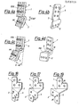
- FIGS. 1 and 2 show a pan fragment fixation in humans
- FIG. 3 shows a diagrammatic, schematic view of a plate shape for use according to FIG. 1
- FIG. 4 shows a corresponding view of a plate shape for use according to FIG. 2
- 4a, 4b, 4c and 4d show advantageous plate shapes.
- FIG. 5 shows a plate shape in which a substantially wedge-shaped transition zone for contact with the osteotomy surface of the acetabular fragment adjoins a substantially wedge-shaped transition zone for contact with the osteotomy surface of the ilium;
- Figures 6 to 9 show details of a plate shape of the type shown in Figure 3 and Figures 10 to 13 variants thereof;
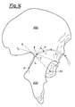
- 14 shows an x-ray projection of the pan region with a construction for determining a polygonal one Course of osteotomy in the ilium;
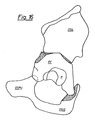
- FIG. 15 is an X-ray projection according to FIG. 14 after osteotomies and pan fragment pivoting and
- FIG. 16 shows a perspective view of the situation according to FIG. 15 and FIGS. 17 to 19 show plates intended for use in dogs.
- FIG. 1 is a ventrolateral view of a left-sided acetabular fixation after a triple osteotomy with an offset of the acetabular roof ventrally and laterally. Due to the displacement of the acetabular roof, part of the osteotomy surface 12 (dashed area) on the acetabular fragment PF protrudes ventrolaterally over the outer surface of the ilium (0s ilium, in the drawing OSIL). The pan is labeled P on the pan fragment PF. The foramen obturatum and the foramen ischiadicum are labeled with FO and FI, respectively.
- the iliac osteotomy was performed essentially as a cylindrical incision, i.e. the osteotomy surfaces on the socket fragment and ilium are roughly cylindrical surfaces.
- the aim is preferably to even perform a spherical osteotomy, since this results in the maximum congruence after the acetabular roof has been displaced.
- osteotomy surface On the ischium (Os ischii, in the drawing OSIS) the osteotomy surface can be seen as a dashed area; The fixation between pubis (0s pubis, in the drawing OSPU) and socket fragment (PF) is shown as a wire cerclage with two screws.
- the proximal section 1 of the fixation plate is screwed to the ventral section of the iliac scoop and the distal section 2 of the fixation plate is screwed to the socket fragment.
- a transition zone 3 is arranged, which forms a wedge that opens ventrally and supports a part of the portion of the osteotomy surface 12 projecting ventrolaterally over the iliac surface on the socket fragment proximally.
- the wedge zone 3 forms a widening of the ilium laterally. The greatest width of the wedge zone is at the ventral edge of the plate.
- Fig. 2 is a representation corresponding to Fig. 1, but the socket fragment has been largely medialized according to the indication, so that the osteotomy surface 12 of the socket fragment no longer protrudes ventrolaterally over the outer surface of the ilium, but rather is flush with it in the ventral region of the ilium in the dorsal direction, it jumps medially under the osteotomy surface 13 of the ilium. It can be seen from FIG. 2 that the fixation plate - as in FIG.
- the pubic bone is appropriately osteectomized to enable medialization and, if necessary, lateral tilting.
- fixation plates corresponding to the conditions in FIGS. 1 and 2 are schematically placed side by side for comparison in the medioproximal view in order to make the differences described clear, 4 in each case being the ventral edge and 5 the dorsal edge. It can be seen that the plate according to FIG. 3 is used for the situation according to FIG. 1 and the plate according to FIG. 4 for the situation according to FIG. 2.
- FIGS. 4 and 4a show a section and a view of a fixation plate, in particular for a human being, wherein the socket fragment PF is rotated, pivoted and tilted outwards with respect to the iliac bone OSIL.
- the Tilt angle is between 5-60 °.
- the distal section 2 is inclined by 5-60 ° relative to the proximal section 1.
- FIGS. 4b and 4c show a section and a view of a fixation plate, in particular for a human, wherein the socket fragment PF is rotated, pivoted, tilted outwards and medialized relative to the iliac bone OSIL.
- the medialization M is up to 13 mm, preferably 5-13 mm, depending on the size of the patient.
- the tilt angle between the iliac bone OSIL and the socket fragment PF is set to 5-60 °, the inclination of the distal section 2 relative to the proximal section 1 is correspondingly 5-60 °.
- the length of the ventral end of the transition zone 3 thus corresponds to the necessary medialization M.
- the transition zone 3 widens dorsally from the ventral end in accordance with the angle that the proximal section 1 and the distal section 2 enclose.
- the transition zone 3 is thus formed by a medialization section MA determined by the desired medialization and a wedge-shaped section due to the angle between the sections 1 and 2. This fixation plate has the greatest width at the dorsal margin.
- FIG. 4 schematically shows an embodiment of a fixation plate, corresponding to the views of FIGS. 3 and 4, in which the two support options described above are combined.
- the use of such a plate is indicated if, in the end position of the socket fragment to be fixed, the lateral osteotomy edges on the gut bone and on the socket fragment intersect one another in the area of the fixation plate.
- the plate thus has a proximal transition wedge zone 3a dorsally and a distal transition wedge zone 3b ventrally, the proximal transition wedge zone 3a being provided for support against the osteotomy surface 13 on the ilium and the distal transition wedge zone 3b for support against the osteotomy surface 12 of the acetabular fragment.
- the size and position of the wedge zones 3a, 3b on the plate depends on the desired end position of the socket fragment.
- FIG. 6 The plate according to Figs. 6 to 9 is spatially curved and Fig. 6 shows a medial view, i.e. 7 is a view from the ventral, FIG. 8 is a view from the distal and FIG. 9 is a section IX-IX from FIG. 6.
- the plate has a longer proximal section 1 with six screw seats and a shorter distal section 2 with two screw seats, a wedge-shaped transition zone 3 having the greatest width at the ventral edge 4 of the plate being interposed between these sections.
- the sections 1 and 2 are thus at an angle to one another (see in particular FIG. 8), the dorsal edge 5 practically running in a uniform curve and in the ventral edge 4 there is a double bend with obtuse angles. This can be seen in particular from FIG. 7.
- the transition edges 6 and 8 between the distal section 2 or the proximal section 1 and the transition zone 3 have the shape of a circular arc section.
- FIG. 9 shows the asymmetrical countersink 7,7 'of the screw seats, which are inclined in opposite directions in the screw seats in the distal section 2 in one direction 7 and in the screw seats in the proximal section 1 in the other direction 7'.
- the screws are not inserted axially into the seats, but slightly offset distally in the distal section and slightly proximal in the proximal section.
- the plate When screwing in, the plate would be stretched by the wedge action of the countersunk heads of the screws on the wedge surfaces of the countersinks between distal section 2 and proximal section 1 if it were not rigid.
- the two parts to be connected by the plate namely the ilium with which the proximal section 1 and the socket fragment to which the distal section 2 is screwed, are instead clamped together, i.e. with their end faces pressed against each other.
- FIG. 10 shows a plate with a transition zone 3 ⁇ widened ventrally with respect to the proximal area 1 and the same distal area 2.
- Fig. 11 shows a similar plate as the plate according to Fig.10, but in which the transition zone 3 ⁇ and the distal area compared to the proximal area 1 are widened dorsally.
- Fig. 12 shows a plate which engages over the iliac osteotomy in the area up to the sciatic foramen and which is screwed into the ventral and dorsal end sections, so that an additional fixation in the area of the sciatic foramen is realized.
- FIG. 13 shows a plate similar to the plate according to FIG. 12, but with the transition zone 3 ⁇ and the distal region 2 being widened ventrally with respect to the proximal region 1, as can also be seen from FIGS. 10 and 11.
- the central region of the proximal section 1 is cut out, so that the proximal region is essentially formed from two lobes, the ventral lobe 1 being used for fixation between the supporting parts of the cranial and caudal pelvic pillar and the dorsal lobe 1 ⁇ being used for fixation in the area of the sciatic foramen.
- the proximal area 1 of the plate can also - as indicated by dashed lines - be continuous, as in the embodiment according to FIG. 12; likewise, in the embodiment according to FIG. 12, the proximal section middle area can be cut out accordingly.
- the spatial curvature or curvature of the plate for positive engagement with the iliac scoop and pan fragment can be clearly seen from the figures. It can be seen from FIG. 9 that the proximal section 1 is convex in the proximal / distal direction to the iliac scoop and from FIG. 8 that the distal section 2 is concave in the ventral / dorsal direction towards the socket fragment. 7, 8, 10 and 11 it can also be seen that the proximal section 1 is additionally concavely curved in the ventral / dorsal direction towards the iliac scoop. It can also be seen from FIGS. 9 and 10 to 13 that the distal section 2 is additionally convex in the proximal / distal direction towards the socket fragment.
- ventrally elongated transition zone 3 ⁇ does not support the entire laterally projecting osteotomy surface on the socket fragment proximally, but only the lateral edge thereof.
- the extended region 3 ⁇ is narrower than a curve given by the wedge angle, so that the greatest width of the wedge-shaped transition zone is not located on the ventral edge 4 of the plate.
- a screw cannot be inserted dorsally.
- fixation plates according to the invention can be formed from all materials known for this purpose, in particular from stainless steel alloys and titanium.
- the iliac osteotomy should be performed in order to maintain the highest possible congruence of the osteotomy surfaces after the acetabular roof has been relocated.
- a spherical osteotomy is to be regarded as the ideal geometrical model, but it is difficult to achieve with surgery. It has now been found that a well practicable approach lies in making plane polygonal sections depending on the swivel angle determined by X-ray diagnosis. For this purpose, flat, as long as possible approximate osteotomies are placed along an arc, each at the same angle to one another, at least two flat partial osteotomies should be placed on the ilium.
- FIG. 16 Such an osteotomy guide can be seen in FIG. 16; the manner of representation corresponds to that of FIGS. 1 and 2. It can be seen that the socket fragment in the dorsal region is set somewhat medially, so that in the area of the fixation plate, not shown, the osteotomy surface on the socket fragment with respect to the lateral osteotomy edge on the ilium is anterior to laterally anterior and posterior jumps in the media. This corresponds to the use of a plate according to FIG. 5 which is adapted to the level of the cut in terms of the edge profile. The level osteotomies on the ilium and ischium are clearly visible. The geometry of the osteotomy guide according to FIG. 16 can be seen from FIGS. 14 and 15 in a medial view.
- FIG. 14 is a schematic illustration of a right hip joint in the plane of the ilium, as can be easily obtained by radiography. The following conditions should be observed: X-ray source centered on the joint, beam direction approximately perpendicular to the plane of the ala ossis ilii, and approximately flush with the pubis.
- This faux-profile image is used to determine the guidance of the osteotomies in the ilium and ischium.
- X-ray images of the joint in different spatial views can be used to determine the approximate swivel angle for the socket fragment, in particular the main angle, which relates to the swiveling towards the ventrolateral. In humans, this angle can be in the range from approximately 25 to approximately 45 °, frequently in the range from 28 to 38 °, with severe hip dysplasia cases usually requiring a pivoting in the region of approximately 38 °. The location of the pan center is also determined by these recordings.
- Fig. 14 One of the approximate methods for determining the osteotomies in the ilium can be seen in Fig. 14.
- the sciatic incisura is extended proximally; it forms the first straight line.
- a tangent T 1 from the socket center PZ to the projection of the curvature of the ilium is placed next to the incisura ischiadica major and a tangent T 2 from this projection to the projection of the ventroproximal socket edge. It has been shown that the intersection I of the extension of the incisura ischiadica major with the tangent T1 and the intersection II with the tangent T2 form the first corner point of the polygon in question, the intersection I the small pivot angle and the intersection II the large swivel angles is assigned.
- the pan fragment pivoted according to the construction according to FIG. 14 can be seen in FIG. 15.
- the bone wedge remaining in the area of the sciatic foramen after the incision geometry is ectomized in the extension of 1 and the distance to the dorsal end point E 1 of the ischial osteotomy is chosen to be correspondingly greater than 10, so that the osteotomy surfaces abut each other in this area too.
- the shape of the fixation plates must of course be adapted to the straight course of the osteotomy, particularly with regard to the edges of the wedge-shaped transition zones.
- pan center PZ is not selected as the swivel center, leg shortening or lengthening can also be achieved depending on the indication.
- 17, 18 and 19 are craniolateral views of plates for use in a triple pelvic osteotomy with axial, horizontal acetabular tilting in dogs, the course of the osteotomy in the ilium and in the ischium being perpendicular to the body axis of the dog, ie in the plane of the wedge zone 3, and the Axis 14 around which the pan fragment is pivoted laterally, runs parallel to the lumbar spine of the dog. It can be seen that the greatest width of the wedge zone 3 lies at the dorsal edge 5 of the plate. In this way, the swivel axis 14 can be placed close to the center of the pan, which achieves the functionally most favorable joint geometry after pan tilting in the dog.
- the swivel angle that is the angle at which the sections 1 and 2 are in relation to one another, lies in the dog in the range of approximately 20 to 70 °, preferably in the range of 30 to 60 °, in particular approximately 45 °. Holes for a possible cerclage are marked with 20.
Abstract
Es wird eine Knochenfixationsplatte zur Schraubfixierung des Pfannenfragments am Darmbein nach Beckenosteotomien mit Pfannendachschwenkung, insbesondere beim Menschen, vorgeschlagen, die vor allem einen proximalen Abschnitt (1) zur, insbesondere mindestens im wesentlichen formschlüssigen, Anlage an der Darmbeinschaufel und einen distalen Abschnitt (2) zur, insbesondere mindestens im wesentlichen formschlüssigen, Anlage am Pfannenfragment aufweist, wobei die Abschnitte (1, 2) in einem Winkel zueinander stehen, der beim Menschen im Bereich von 10 bis 50°, weiter bevorzugt bei etwa 30°, und beim Hund im Bereich von etwa 20 bis 70°, vorzugsweise im Bereich von 30 bis 60°, insbesondere bei etwa 45°, liegt, und wobei zur Bildung dieses Winkels zwischen den Abschnitten (1, 2) eine im wesentlichen keilförmige Übergangszone (3) ausgebildet ist, deren größte Breite vorzugsweise am ventralen Rand der Platte gelegen ist. Diese Platte ist Teil eines Fixationssystems, bei dem gegebenenfalls im Bereich des Schambeins eine Drahtcerclage über zwei Schrauben vorgesehen ist.A bone fixation plate for screw fixation of the socket fragment on the ilium after pelvic osteotomies with tilting of the acetabular roof, in particular in humans, is proposed, which primarily has a proximal section (1) for, in particular at least essentially positive, contact with the iliac scoop and a distal section (2) , in particular at least essentially form-fitting, on the pan fragment, the sections (1, 2) being at an angle to one another which in humans is in the range from 10 to 50 °, more preferably at about 30 °, and in dogs in the range of is approximately 20 to 70 °, preferably in the range of 30 to 60 °, in particular approximately 45 °, and a substantially wedge-shaped transition zone (3) is formed between the sections (1, 2) to form this angle, the largest of which Width is preferably located on the ventral edge of the plate. This plate is part of a fixation system, in which a wire cerclage over two screws is optionally provided in the region of the pubic bone.
Description
Die Erfindung betrifft eine Knochenfixationsplatte zur Schraubfixierung des Pfannenfragments am Darmbein nach Beckenosteotomien mit Pfannendachschwenkung, insbesondere beim Menschen, bei der die Pfanne im Bereich des Darm- und Sitzbeines mit einem gegebenenfalls gemeinsam angelegten Schnitt, insbesondere mit im wesentlichen entlang eines Zylindermantels erfolgender Schnittführung, und im Bereich des Schambeines mit einem gesonderten, insbesondere ebenen Schnitt umtrennt wurde, wobei die stabile Fixation dieser Platte an der Facies glutaea des cranialen Beckenpfeilers der Darmbeinschaufel erfolgt.The invention relates to a bone fixation plate for screw fixation of the socket fragment on the ilium after pelvic osteotomies with tilting of the roof of the socket, in particular in humans, in which the socket in the region of the ilium and ischium with an optionally joint cut, in particular with an incision made essentially along a cylinder jacket, and in Area of the pubic bone was separated with a separate, in particular flat, incision, the stable fixation of this plate taking place on the facies glutaea of the cranial pelvic pillar of the iliac scoop.
Es gibt verschiedene Techniken der Zweifach- und Dreifach-Osteotomien für die Hüftpfannenschwenkung bei Hüftgelenksdysplasien, insbesondere im Humanbereich. Als erfolgversprechendste ist eine Dreifach-Osteotomie anzusehen, bei der die Pfanne pfannennahe umtrennt wird, weil sich danach die Pfanne sowohl nach lateral als auch nach ventral neigen läßt. Dazu ist eine Trennung am Darmbein, am Sitzbein und am Schambein erforderlich. Zuerst wird die Sitzbein-Osteotomie durchgeführt, wobei vom Foramen ischiadicum zum Foramen obturatum durchtrennt wird, das Sitzbein dorsal aber mit Tuber, Spina und den zum Kreuzbein ziehenden Bändern erhalten bleibt. Hiebei ist zu beachten, daß das Foramen obturatum wirklich getroffen wird, wobei auch die durch den Umstand, daß das Sitzbein zur Membrana obturata spitz ausgezogen ist, gebildete Knochenleiste durchtrennt werden muß, damit letztlich die Hüftpfanne gedreht werden kann.There are various techniques of double and triple osteotomies for the acetabular tilt in hip dysplasia, especially in the human area. The most promising is a triple osteotomy, in which the pan is separated near the pan, because the pan can then be tilted both laterally and ventrally. This requires a separation on the ilium, the ischium and the pubis. First, the ischial osteotomy is performed, cutting from the sciatic foramen to the obturate foramen, but maintaining the ischium dorsally with tuberosity, spina and the ligaments pulling towards the sacrum. It should be noted that the foramen obturatum is really hit, and the bone ridge formed by the fact that the ischium is pointed to the obturate membrane must also be severed so that the acetabulum can ultimately be rotated.
Anschließend wird die Osteotomie des Schambeins dicht neben dem Hüftgelenk durchgeführt. Sie wird annähernd parallel zur Körperachse in leicht schräger Richtung in das Foramen obturatum gelegt, um zu erzielen, daß nach der Pfannendachschwenkung noch Knochenkontakt erhalten bleibt, um eine rasche anschließende Knochendurchbauung zu ermöglichen.The pubic bone osteotomy is then performed close to the hip joint. It is placed approximately parallel to the body axis in a slightly oblique direction in the obturate foramen in order to ensure that bone contact is retained after the acetabular roof has been swiveled in order to enable rapid subsequent bone development.
Als dritte Stufe erfolgt die Darmbein-Osteotomie. Vorher wird ein Steinmann-Nagel als spätere Hilfe beim Verdrehen und Schwenken der Pfanne, parallel zur geplanten, schräg nach medial absteigenden Osteotomie in den Beckenknochen eingeschossen. Die Darmbein-Osteotomie erfolgt in einer Ebene, zuerst mit der oszillierenden Säge, dann mittels Meißeln.The third stage is the iliac osteotomy. Before that, a Steinmann nail is injected into the pelvic bones as a later aid when twisting and swiveling the pan, parallel to the planned osteotomy, which descends medially. The iliac osteotomy is done in one plane, first with the oscillating saw, then with chisels.
Anschließend wird die Pfanne über den Hüftkopf verdreht und verschwenkt; jedenfalls in dem Ausmaß, in dem vorher der Hüftkopf abgespreizt werden mußte, um unter das Pfannendach zu kommen. Dazu wird das Pfannendach am Steinmann-Nagel über den Hüftkopf und bei Bedarf auch nach vorne gezogen, sowie der mediale Schambeinast im Rotationssinne nach aufwärts gedrückt. Anschließend wird die Pfanne durch händischen Druck medialisiert und ein guter Kontakt mit dem Schambein hergestellt.The pan is then turned and swiveled over the femoral head; at least to the extent that the femoral head had to be spread out beforehand, to get under the pan roof. For this purpose, the socket on the Steinmann nail is pulled over the femoral head and, if necessary, also forward, and the medial pubic branch is pushed upwards in the sense of rotation. Then the pan is medialized by hand pressure and good contact is made with the pubic bone.
Es soll eine weitgehende horizontale Überdachung des Kopfes durch die Sklerosierungszone des Pfannendaches bzw. die Facies lunata erzielt werden, da dies die geeignete Fläche zur Aufnahme und Übertragung durch Belastung des Beins erzeugter Druckkräfte ist. Die anschließende Fixierung der Pfanne erfolgt über durch die Beckenschaufel in vier verschiedenen Richtungen in das Pfannenfragment eingeschossene Kirschnerdrähte, deren Hinterenden am Beckenkamm abgezwickt und umgebogen werden. Diese Art der Fixation ist schwierig, oftmals wenig stabil und führt in vielen Fällen nicht zum gewünschten Erfolg, d.h. die Pfanne wackelt, die Knochendurchbauung ist stark verzögert und der Patient muß sich mit einer mehrwöchigen Liegezeit im Körperbeckengips abfinden.An extensive horizontal roofing of the head should be achieved through the sclerotherapy zone of the acetabular roof or the facies lunata, since this is the suitable area for absorbing and transmitting pressure forces generated by loading the leg. The pan is then fixed in place using Kirschner wires inserted into the pan fragment in four different directions through the pelvic blade, the rear ends of which are pinched off and bent over on the pelvic crest. This type of fixation is difficult, often not very stable and in many cases does not lead to the desired success, i.e. the pan wobbles, the bone build-up is greatly delayed and the patient has to settle in the plaster of the pelvis for several weeks.
Ein wesentlicher Grund dafür ist die instabile Fixation über Kirschnerdrähte, die aber nicht zuletzt deswegen nötig ist, weil die Darmbein-Osteotomie als ebener Schnitt erfolgt, somit bei Verschwenken der Pfanne nach ventral und lateral ein offener Keilspalt zwischen Darmbeinschaufel und Pfannenfragment entsteht, der in aller Regel durch einen aus dem Beckenkamm herausgesägten Knochenkeil, der in diesen Spalt implantiert wird, ausgefüllt werden muß, so daß das so entstandene Dreikörpersystem fixiert und darüber hinaus auch von der Knochendurchbauung erfaßt werden muß.One of the main reasons for this is the unstable fixation via Kirschner wires, which is not least necessary because the iliac osteotomy is performed as a flat incision, so when the pan is pivoted ventrally and laterally, an open wedge gap between the iliac scoop and the pan fragment arises, which occurs in all Usually it has to be filled in by a bone wedge sawn out of the iliac crest, which is implanted in this gap, so that the resulting three-body system has to be fixed and, moreover, it has to be grasped by the bone structure.
Es wurde nunmehr gefunden, daß man nach Dreifach-Osteotomien die Pfanne stabil über eine besonders ausgebildete Platte an der Facies glutaea des cranialen Beckenpfeilers der Darmbeinschaufel fixieren kann, d.h. auf die Anwendung von Kirschnerdrähten und die Keilentnahme aus der Darmbeinschaufel bzw. die Knochenkeilinterposition nicht mehr angewiesen ist.It has now been found that, after triple osteotomies, the pan can be fixed stably to the facies glutaea of the cranial pelvic pillar of the iliac vein via a specially designed plate, i.e. is no longer dependent on the use of Kirschner wires and the removal of wedges from the iliac scoop or the interposition of bone wedges.
Diese erfindungsgemäße anatomische Knochenplatte ist vor allem dadurch gekennzeichnet, daß die Platte einen proximalen Abschnitt zur, insbesondere mindestens in wesentlichen formschlüssigen, Anlage an der Darmbeinschaufel und einen distalen Abschnitt zur, insbesondere mindestens im wesentlichen formschlüssigen, Anlage am Pfannenfragment aufweist, wobei die Abschnitte in einem Winkel zueinander stehen, der im Bereich von 10 bis 50°, bevorzugt bei etwa 30°, leigt, und wobei zwischen den Abschnitten eine im wesentlichen keilförmige Obergangszone ausgebildet ist, deren größte Breite vorzugsweise am ventralen Rand der Platte gelegen ist.This anatomical bone plate according to the invention is primarily characterized in that the plate has a proximal section for, in particular at least essentially form-fitting, contact with the iliac scoop and a distal section for, in particular at least essentially positive-fitting, contact with the pan fragment, the sections in stand at an angle to one another which is in the range from 10 to 50 °, preferably at approximately 30 °, and wherein an essentially wedge-shaped transition zone is formed between the sections, the greatest width of which is preferably located on the ventral edge of the plate.
Diese anatomische Fixationsplatte wird mit Darmbeinschaufel und dem Pfannenfragment verschraubt und stützt bei einer Ausführungsform mit ihrer Übergangszone den Osteotomierand des Pfannenfragments, der infolge der Verlagerung des Pfannenfragments, insbesondere des Schwenkens nach ventral und des Kippens nach lateral, über die Darmbeinschaufelaußenfläche vorsteht, nach proximal ab, d.h. gegenüber dem Belastungsdruck am Bein.This anatomical fixation plate is screwed to the iliac scoop and the socket fragment and, in one embodiment, supports with its transition zone the osteotomy edge of the socket fragment, which protrudes proximally due to the displacement of the socket fragment, in particular the swiveling to the ventral and the tilting laterally, over the outer surface of the iliac scoop. ie compared to the pressure on the leg.
In einem ganz anderen Zusammenhang, nämlich zur Bildung eines künstlichen Pfannendachrandes bei sonst unverändertem Hüftgelenk, also ohne Beckenosteotomie, ist aus der DE-AS 24 10 057 eine im Pfannenbereich anbringbare Knochenplatte bekannt geworden. Die Fixierung der bekannten Platte erfolgt am Darmbein durch zwei proximale Laschen, zwischen denen eine Ausnehmung zur Aufnahme der Beckenkammbasis vorgesehen ist; die Platte liegt am Pfannendach auf und ihr nach ventral eingebogener distaler Rand bildet den Pfannendachrand, mit anderen Worten wird der proximale Bereich der Pfanne - das Pfannendach - nach vorwiegend lateral künstlich verbreitert, um eine Luxation des Femurkopfs nach proximal zu verhindern. Der Zweck dieser bekannten Platte und demzufolge auch ihre geometrische Ausbildung ist von denen der erfindungsgemäßen Platte völlig verschieden.In a completely different context, namely for the formation of an artificial socket roof edge with an otherwise unchanged hip joint, that is to say without a pelvic osteotomy, DE-AS 24 10 057 has disclosed a bone plate which can be attached in the socket area. The known plate is fixed on the ilium by two proximal tabs, between which a recess is provided for receiving the base of the iliac crest; the plate rests on the acetabular roof and its distally distally bent edge forms the acetabular roof edge, in other words the proximal area of the socket - the acetabular roof - is artificially widened predominantly laterally in order to prevent proximal luxation of the femoral head. The purpose of this known plate and consequently also its geometric design is completely different from that of the plate according to the invention.
Bei Anwendung der erfindungsgemäßen anatomischen Knochenplatte ist insbesondere eine stabile Fixation durch Kompressionsosteosynthese zwischen dem Pfannenfragment und der Darmbeinschaufel und eine frühe Belastbarkeit des Hüftgelenkes und der Extremität erzielbar, es handelt sich somit um eine primär belastungs- und übungsstabile Fixierung. Das Ergebnis ist eine rasche postoperative Mobilisierung der Patienten.When using the anatomical bone plate according to the invention, in particular a stable fixation by compression osteosynthesis between the socket fragment and the iliac scoop and an early resilience of the hip joint and the extremity can be achieved, so it is a primarily load and exercise stable fixation. The result is rapid postoperative patient mobilization.
Die stabile Fixation der Platte an der Darmbeinschaufel erfolgt vorteilhaft so, daß damit der optimale Druckaufnahmebereich in der Darmbeinschaufel mit Bezug auf die O-Stellung des Femur erfaßt ist, also am Vorderteil der Ala Ossis ilii, knapp distal vom Tuberculum glutaeum, beginnend etwa einfingerbreit dorsal von der Spina iliaca anterior superior und der Spina iliaca anterior inferior und etwa bis zur Linea glutaea anterior, besonders in dessen ventralem Bereich zwischen den tragenden Teilen des kranialen und kaudalen Beckenpfeilers.The stable fixation of the plate to the iliac vein advantageously takes place in such a way that the optimal pressure absorption area in the iliac vein is recorded with reference to the O position of the femur, i.e. at the anterior part of the ala ossis ilii, just distal to the gluteal tubercle, beginning approximately one finger width dorsally of the anterior superior iliac spine and the Anterior inferior iliac spine and approximately to the anterior gluteal line, particularly in the ventral area between the supporting parts of the cranial and caudal pelvic pillars.
Ein wesentlicher Vorteil ergibt sich, wenn die zur Pfannendachschwenkung nötige Darmbein-Osteotomie nicht wie bisher als ebener Schnitt erfolgt, so daß nach dem Verschwenken des Pfannenfragments nach ventral und lateral durch insbesondere im wesentlichen einem Zylindermantel folgende Osteotomieflächen zwischen Pfannenfragment, Darm- und Sitzbein der - für die biomechanische Lastübertragung vom Femur über die Pfanne in das Darmbein, sowie für die postoperative Knochendurchbauung - so wichtige Formschluß zwischen Pfannenfragment, Darmbeinschaufel und Sitzbein erzielt wird.A major advantage is obtained if the iliac osteotomy required for pivoting the acetabular roof is not carried out as a flat cut as before, so that after the pan fragment has been pivoted ventrally and laterally, the osteotomy surfaces between the pan fragment, intestine and ischial bone, which essentially follow a cylinder jacket, for the biomechanical load transfer from the femur via the socket to the ilium, as well as for postoperative bone penetration - so important positive locking between the socket fragment, iliac scoop and ischium is achieved.
Diese Schnittführung, welche zur Einhaltung der Kongruenzbedingung, zur Erzielung des Formschlusses zwischen Pfannenfragment und Darmbeinschaufel an die Incisura ischiadica major herangeführt wird, in Verbindung mit dem Einsatz der erfindungsgemäßen anatomisch formschlüssigen Knochenplatte (Fixationsplatte) ergibt die direkte, sowie übungs- und belastungsstabile Kompressionsosteosynthese zwischen Darmbein und Pfannenfragment ohne Knochenkeilinterposition und damit die praktisch unmittelbare Wiederbelastbarkeit des Hüftgelenkes und des Beins; in Verbindung mit einer ungehinderten Knochendurchbauung - ohne der sonst üblichen mehrwöchigen Ruhigstellung mittels Körperbeckengipsverband - ist eine rasche postoperative Mobilisierung möglich.This incision, which is introduced to the incisura ischiadica major in order to comply with the congruence condition, to achieve the form fit between the socket fragment and iliac scoop, in connection with the use of the anatomically form-fitting bone plate (fixation plate) according to the invention results in the direct, exercise and load-stable compression osteosynthesis between the ilium and socket fragment without bone wedge interposition and thus the practically immediate resilience of the hip joint and leg; In connection with an unhindered bone development - without the usual immobilization over several weeks by means of a pelvic cast - a rapid postoperative mobilization is possible.
Diese Schnittführung, welche in einem Abstand von mindestens 10 mm, vorzugsweise in einem größeren Abstand,vom Pfannenrand geführt wird, sichert darüber hinaus auch den formschlüssigen Knochenkontakt zwischen Pfannenfragment und Sitzbein, ohne den Beckenraum medial einzuengen.This incision, which is carried out at a distance of at least 10 mm, preferably at a greater distance, from the socket edge also ensures the form-fitting bone contact between the socket fragment and the ischial bone without narrowing the pelvic space medially.
Die Schambein-Osteotomie wird - wie die Sitzbeinosteotomie - vorteilhaft als ebener Schnitt durchgeführt, wobei die Schnittebene annähernd senkrecht zur Crista obturatoria steht. Diese Schnittführung sichert letztendlich auch den bündigen Knochenkontakt zwischen dem Pfannenfragment und dem Schambein nach der Pfannendachverlagerung.The pubic bone osteotomy - like the ischial osteotomy - is advantageously carried out as a flat incision, the incision plane being approximately perpendicular to the obstructed crista. Ultimately, this incision also ensures that the bone is flush between the socket fragment and the pubic bone after relocation of the socket roof.
Die Ausbildung der erfindungsgemäßen anatomischen Knochenfixationsplatte zum Formschluß mit der Darmbeinschaufel und dem Pfannenfragment erfordert natürlich verschiedene Plattenprofile für die linke bzw. rechte Seite des Beckens, sowie eine Anpassung an die Beckenoberfläche. Die Platten sind in ihrer form und Größe den sich nach der Pfannendachverlagerung ergebenden proximalen und distalen Auflagebereichen so formschlüssig angepaßt, daß sie intraoperativ keiner Formkorrektur bedürfen. Auch der Winkel zwischen dem proximalen und dem distalen Plattenabschnitt wird auf die Indikation und die chirurgischen Bedürfnisse abgestellt, so daß eine Anpassung an die Größe und Art der Pfannendachverlagerung möglich ist.The formation of the anatomical bone fixation plate according to the invention for positive locking with the iliac scoop and the pan fragment naturally requires different plate profiles for the left or right side of the pelvis, as well as an adaptation to the pelvic surface. The shape and size of the plates are so positively adapted to the proximal and distal contact areas that result after the acetabular roof has been displaced that they do not require any shape correction intraoperatively. The angle between the proximal and the distal plate section is also adapted to the indication and the surgical requirements, so that an adaptation to the size and type of the acetabular roof displacement is possible.
Hiebei kann auch der Fall eintreten, daß das Pfannenfragment nach seiner Verlagerung, insbesondere nach Schwenken nach ventral und Kippen nach lateral, aus bieomechanischen Gründen noch als Ganzes medialisiert werden muß, beispielsweise um Distanzen zwischen 4 und 10 mm. Dies hat zur Folge, daß das Pfannenfragment in der Endlage mit seinem Osteotomierand nicht mehr oder nur teilweise nach lateral über die Darmbeinaußenfläche vorsteht, so daß es angezeigt ist, nicht den Osteotomierand des Pfannendachfragments an der Übergangszone der Fixationsplatte, sondern die Übergangszone der Fixationsplatte im dorsalen Bereich an der Osteotomiefläche des Darmbeins, jeweils nach proximal abzustützen.In this case, the pan fragment may also have to be medialized as a whole for bieomechanical reasons, for example by distances between 4 and 10 mm, after its displacement, in particular after swiveling to the ventral and tilting to the side. As a result, the acetabular fragment in the end position no longer or only partially protrudes laterally beyond the outer surface of the ilium, so that it is indicated not the osteotomy edge of the acetabular fragment at the transition zone of the fixation plate, but the transition zone of the fixation plate in the dorsal region Support the area on the osteotomy surface of the ilium, in each case proximally.
Zu diesem Zweck ist ein weiteres Kennzeichen der Fixationsplatte gemäß der vorliegenden Erfindung, daß die im wesentlichen keilförmige Übergangszone zur Anlage an der Osteotomiefläche des Pfannenfragments und/oder zur Anlage an der Osteotomiefläche des Darmbeins ausgebildet ist.For this purpose, a further characteristic of the fixation plate according to the present invention is that the essentially wedge-shaped transition zone is designed to rest on the osteotomy surface of the acetabular fragment and / or to rest on the osteotomy surface of the ilium.
Der Fall, wo es angezeigt ist, beide dieser Abstützungsmöglichkeiten zu verwirklichen, ist z.B. dann gegeben, wenn das Pfannendachfragment dorsal nach medial und ventral nach lateral verschwenkt wird, so daß die Osteotomiefläche des Pfannenfragments im Ventralbereich über die Außenfläche des Darbeins vorspringt und im Dorsalbereich unter die Osteotomiefläche des Darmbeins einspringt.The case where it is advisable to implement both of these support options is e.g. then given when the acetabular roof fragment is pivoted dorsally medially and ventrally laterally, so that the osteotomy surface of the acetabular fragment protrudes in the ventral region over the outer surface of the intestine and in the dorsal region under the osteotomy surface of the ilium.
Nach einem weiteren Kennzeichen der erfindungsgemäßen Fixationsplatte schließt somit an eine im wesentlichen keilförmige Übergangszone zur Anlage an der Osteotomiefläche des Pfannenfragments dorsal eine im wesentlichen keilförmige Übergangszone zur Anlage an der Osteotomiefläche des Darmbeins an.According to a further feature of the fixation plate according to the invention, an essentially wedge-shaped transition zone for contacting the osteotomy surface of the acetabular fragment adjoins a substantially wedge-shaped transition zone for contacting the osteotomy surface of the ilium.
Insbesondere ist die erfindungsgemäße anatomische Knochenfixationsplatte so ausgebildet, daß die Abschnitte der Platte an der dem Pfannenfragment zugewandten Seite zur Übergangszone hin jeweils eine der Osteotomieführung angepaßte Kante, vorzugsweise eine Kante mit im wesentlichen Kreisbogenabschnittform (dessen Radius von Größe des menschlichen Patienten abhängt) aufweisen. Die erfindungsgemäße Platte ist entsprechend der Ausbildung der Knochenoberflächen im Auflagebereich vorzugsweise in allen drei Ebenen des Raums gekrümmt.In particular, the anatomical bone fixation plate according to the invention is designed such that the sections of the plate on the side facing the socket fragment toward the transition zone each have an edge adapted to the osteotomy guide, preferably an edge with an essentially circular segment shape (the radius of which depends on the size of the human patient). The plate according to the invention is preferably curved in all three planes of the space in accordance with the formation of the bone surfaces in the support area.
Wie bereits erwähnt, wird die erfindungsgemäße Platte mit der Darmbeinschaufel und dem Pfannenfragment unter Kompression mit Kortikalisschrauben, verschraubt. Zu diesem Zweck ist die erfindungsgemäße Platte proximal und distal mit exzentrischen Schraubensitzen zum Aneinanderziehen von Darmbeinschaufel und Pfannendach nach dem Zugschraubenprinzip versehen.As already mentioned, the plate according to the invention is screwed to the iliac scoop and the socket fragment under compression with cortex screws. For this purpose, the plate according to the invention is provided proximally and distally with eccentric screw seats for pulling together the iliac scoop and socket roof according to the tension screw principle.
Es wird angestrebt, daß die mit den Knochen in Berührung kommenden Bereiche der erfindungsgemäßen anatomischen Knochenfixationsplatte den Konturen der Facies glutaea entsprechend zum flächigen Anliegen ausgebildet sind, also mit der Knochenoberflächenform eng korrespondieren.The aim is for the regions of the anatomical bone fixation plate according to the invention that come into contact with the bones to be designed to conform to the contours of the gluteal facies, so that they correspond closely to the shape of the bone surface.
Die erfindungsgemäße Knochenfixationsplatte kann bei menschlichen Patienten zwischen 15 und 45 Jahren problemlos eingesetzt werden.The bone fixation plate according to the invention can be used without problems in human patients between 15 and 45 years.
Die Erfindung wird im folgenden an Hand verschiedener Ausführungsbeispiele von erfindungsgemäßen Platten unter Bezugnahme auf die Zeichnung näher erläutert, in der die Fig. 1 und 2 schaubildlich eine Pfannenfragmentfixierung beim Menschen, Fig. 3 eine schaubildliche, schematische Ansicht einer Plattenform zur Anwendung gemäß Fig. 1 und Fig. 4 eine entsprechende Ansicht einer Plattenform zur Anwendung gemäß Fig. 2 zeigt; Fig. 4a, 4b, 4c und 4d zeigen vorteilhafte Plattenformen. Fig. 5 zeigt eine Plattenform, bei der an eine im wesentlichen keilförmige Übergangszone zur Anlage an der Osteotomiefläche des Pfannenfragments dorsal eine im wesentlichen keilförmige Übergangszone zur Anlage an der Osteotomiefläche des Darmbeins anschließt; die Fig. 6 bis 9 zeigen Details einer Plattenform des in Fig. 3 gezeigten Typs und die Fig. 10 bis 13 Varianten davon; Fig. 14 zeigt eine Röntgenprojektion des Pfannenbereichs mit einer Konstruktion zur Ermittlung eines polygonalen Osteotomieverlaufs im Darmbein; Fig. 15 ist eine Röntgenprojektion gemäß Fig. 14 nach erfolgten Osteotomien und Pfannenfragmentverschwenkung und Fig. 16 eine schaubildliche Ansicht der Situation gemäß Fig. 15 und Fig. 17 bis 19 zeigen zur Anwendung beim Hund vorgesehene Platten.The invention is explained in more detail below on the basis of various exemplary embodiments of plates according to the invention with reference to the drawing, in which FIGS. 1 and 2 show a pan fragment fixation in humans, FIG. 3 shows a diagrammatic, schematic view of a plate shape for use according to FIG. 1 and FIG. 4 shows a corresponding view of a plate shape for use according to FIG. 2; 4a, 4b, 4c and 4d show advantageous plate shapes. 5 shows a plate shape in which a substantially wedge-shaped transition zone for contact with the osteotomy surface of the acetabular fragment adjoins a substantially wedge-shaped transition zone for contact with the osteotomy surface of the ilium; Figures 6 to 9 show details of a plate shape of the type shown in Figure 3 and Figures 10 to 13 variants thereof; 14 shows an x-ray projection of the pan region with a construction for determining a polygonal one Course of osteotomy in the ilium; FIG. 15 is an X-ray projection according to FIG. 14 after osteotomies and pan fragment pivoting and FIG. 16 shows a perspective view of the situation according to FIG. 15 and FIGS. 17 to 19 show plates intended for use in dogs.
Es sind jewiels einerseits der linke Beckenabschnitt und anderseits entsprechende linksseitige Fixationsplatten dargestellt.On the one hand the left pelvic section and on the other hand corresponding left fixation plates are shown.
Fig. 1 ist eine Ventrolateralansicht einer linksseitigen Pfannendachfixierung nach erfolgter Dreifachosteotomie mit Pfannendachverlagerung nach ventral und lateral. Durch die Pfannendachverlagerung tritt ein Teil der Osteotomiefläche 12 (strichlierter Bereich) am Pfannenfragment PF über die Außenfläche des Darmbeins (0s ilium, in der Zeichnung OSIL) nach ventrolateral vor. Am Pfannenfragment PF ist die Pfanne mit P bezeichnet. Das Foramen obturatum und das Foramen ischiadicum ist mit FO bzw. FI bezeichnet.1 is a ventrolateral view of a left-sided acetabular fixation after a triple osteotomy with an offset of the acetabular roof ventrally and laterally. Due to the displacement of the acetabular roof, part of the osteotomy surface 12 (dashed area) on the acetabular fragment PF protrudes ventrolaterally over the outer surface of the ilium (0s ilium, in the drawing OSIL). The pan is labeled P on the pan fragment PF. The foramen obturatum and the foramen ischiadicum are labeled with FO and FI, respectively.
Man erkennt, daß die Darmbeinosteotomie im wesentlichen als Zylinderschnitt geführt wurde, d.h. die Osteotomieflächen am Pfannenfragment und Darmbein sind etwa Zylindermantelflächen. Vorzugsweise wird je nach den operativen Gegebenheiten angestrebt, sogar eine sphärische Osteotomie anzubringen, da dies die maximale Kongruenz nach Pfannendachverlagerung ergibt. Durch die Fixationsplatte 1,2,3, die im ventralen Bereich der Darmbeinschaufel (Ala ossis ilii) angebracht ist, werden Pfannenfragment PF und Darmbein an der Osteotomiefläche zusammengespannt, wobei der überstehende Osteotomierand des Pfannenfragments von Übergangszone 3 der Platte nach proximal abgestützt wird.It can be seen that the iliac osteotomy was performed essentially as a cylindrical incision, i.e. the osteotomy surfaces on the socket fragment and ilium are roughly cylindrical surfaces. Depending on the operational circumstances, the aim is preferably to even perform a spherical osteotomy, since this results in the maximum congruence after the acetabular roof has been displaced. The
Am Sitzbein (Os ischii, in der Zeichnung OSIS) erkennt man die Osteotomiefläche als strichlierten Bereich;
Die Fixierung zwischen Schambein (0s pubis, in der Zeichnung OSPU)und Pfannenfragment (PF) ist als Drahtcerclage über zwei Schrauben dargestellt.On the ischium (Os ischii, in the drawing OSIS) the osteotomy surface can be seen as a dashed area;
The fixation between pubis (0s pubis, in the drawing OSPU) and socket fragment (PF) is shown as a wire cerclage with two screws.
Wie aus Fig. 1 ersichtlich, ist der proximale Abschnitt 1 der Fixationsplatte mit dem ventralen Abschnitt der Darmbeinschaufel und der distale Abschnitt 2 der Fixationsplatte mit dem Pfannenfragment verschraubt. Zwischen den beiden Abschnitten 1 und 2 der Fixationsplatte ist eine Übergangszone 3 angeordnet, die einen sich nach ventral öffnenden Keil bildet und die einen Teil des über die Darmbeinfläche nach ventrolateral vorstehenden Abschnitts der Osteotomiefläche 12 am Pfannenfragment nach proximal abstützt. Die Keilzone 3 bildet gewissermaßen eine Verbreiterung des Darmbeins nach lateral. Die größte Breite der Keilzone liegt am ventralen Rand der Platte.As can be seen from FIG. 1, the
Fig. 2 ist eine Fig. 1 entsprechende Darstellung, wobei aber das Pfannenfragment indikationsgemäß weitgehend medialisiert wurde, so daß die Osteotomiefläche 12 des Pfannenfragments nicht mehr über die Außenfläche des Darmbeins nach ventrolateral vorspringt, sondern im ventralen Bereich des Darmbeins etwa mit dieser fluchtet aber nach dorsal zunehmend unter die Osteotomiefläche 13 des Darmbeins nach medial einspringt. Man erkennt aus Fig. 2, daß die Fixationsplatte - ebenso wie gemäß Fig. 1 - den räumlichen Verhältnissen Rechnung trägt und im Plattenbereich an die jeweiligen Oberflächen zur Stützung angeformt ist, wobei die keilförmige Übergangszone 3 sich hier nach dorsal verbreitert, die Osteotomiefläche 13 am Darmbein untergreift und sozusagen eine laterale Verbreiterung der Osteotomiefläche 12 des Pfannenfragments zu deren Abstützung nach proximal am Darmbein bildet. Das Schambein ist zur Ermöglichung der Medialisierung und gegebenenfalls einer Kippung nach lateral entsprechend ostektomiert.Fig. 2 is a representation corresponding to Fig. 1, but the socket fragment has been largely medialized according to the indication, so that the
In Fig. 3 und Fig. 4 sind schaubildlich im Medioproximalsicht Fixationsplatten entsprechend den Verhältnissen in Fig. 1 und 2 zum Vergleich schematisch nebeneinandergestellt, um die beschriebenen Unterschiede deutlich zu machen, wobei jeweils 4 der ventrale Rand und 5 der dorsale Rand ist. Man erkennt, daß die Platte nach Fig. 3 für die Situation gemäß Fig. 1 und die Platte nach Fig. 4 für die Situation nach Fig. 2 zur Anwendung kommt.In FIG. 3 and FIG. 4, fixation plates corresponding to the conditions in FIGS. 1 and 2 are schematically placed side by side for comparison in the medioproximal view in order to make the differences described clear, 4 in each case being the ventral edge and 5 the dorsal edge. It can be seen that the plate according to FIG. 3 is used for the situation according to FIG. 1 and the plate according to FIG. 4 for the situation according to FIG. 2.
Fig. 4 und 4a zeigen einen Schnitt und eine Ansicht einer Fixationsplatte insbesondere für einen Menschen, wobei das Pfannenfragment PF gegenüber dem Darmbein OSIL gedreht,geschwenkt und nach außen gekippt ist. Der Kippwinkel beträgt zwischen 5-60°. Der distale Abschnitt 2 ist gegenüber dem proximalen Abschnitt 1 um 5-60° geneigt.4 and 4a show a section and a view of a fixation plate, in particular for a human being, wherein the socket fragment PF is rotated, pivoted and tilted outwards with respect to the iliac bone OSIL. The Tilt angle is between 5-60 °. The
Fig. 4b und 4c zeigen einen Schnitt und eine Ansicht einer Fixationsplatte insbesondere für einen Menschen, wobei das Pfannenfragment PF gegenüber dem Darmbein OSIL gedreht, geschwenkt, nach außen gekippt und medialisiert wird. Die Medialisierung M beträgt bis zu 13 mm, vorzugsweise 5-13 mm, je nach Größe des Patienten. Der Kippwinkel zwischen Darmbein OSIL und dem Pfannenfragment PF wird auf 5-60° eingestellt, die Neigung des distalen Abschnittes 2 gegenüber dem proximalen Abschnitt 1 beträgt entsprechend 5-60°.4b and 4c show a section and a view of a fixation plate, in particular for a human, wherein the socket fragment PF is rotated, pivoted, tilted outwards and medialized relative to the iliac bone OSIL. The medialization M is up to 13 mm, preferably 5-13 mm, depending on the size of the patient. The tilt angle between the iliac bone OSIL and the socket fragment PF is set to 5-60 °, the inclination of the
Die Länge des ventralen Endes der Übergangszone 3 entspricht somit der notwendigen Medialisierung M. Die Übergangszone 3 erweitert sich vom ventralen Ende ausgehend nach dorsal entsprechend dem Winkel, den der proximale Abschnitt 1 und der distale Abschnitt 2 einschließen. Die Übergangszone 3 wird somit von einem Medialisierungsabschnitt MA bestimmt durch die gewünschte Medialisierung und einen keilförmigen Abschnitt aufgrund des Winkels zwischen den Abschnitten 1 und 2 gebildet. Bei dieser Fixationsplatte ist die größte Breite am dorsalen Rand gelegen.The length of the ventral end of the
Fig. 4 zeigt schematisch entsprechend den Ansichten von Fig. 3 und Fig. 4 eine Ausführungsform einer Fixationsplatte, bei der beide oben beschriebenen Abstützungsmöglichkeiten kombiniert sind. Die Anwendung einer derartigen Platte ist angezeigt, wenn in der zu fixierenden Endlage des Pfannenfragments die lateralen Osteotomiekanten am Darbein und am Pfannenfragment einander im Bereich der Fixationsplatte schneiden. Die Platte weist somit dorsal eine proximale Übergangskeilzone 3a und ventral eine distal Übergangskeilzone 3b auf, wobei die proximale Übergangskeilzone 3a zur abstützenden Anlage an der Osteotomiefläche 13 am Darmbein und die distale Übergangskeilzone 3b zur abstützenden Anlage an der Osteotomiefläche 12 des Pfannenfragments vorgesehen ist. Die Größe und Lage der Keilzonen 3a,3b an der Platte hängt von der gewünschten Endstellung des Pfannenfragments ab.FIG. 4 schematically shows an embodiment of a fixation plate, corresponding to the views of FIGS. 3 and 4, in which the two support options described above are combined. The use of such a plate is indicated if, in the end position of the socket fragment to be fixed, the lateral osteotomy edges on the gut bone and on the socket fragment intersect one another in the area of the fixation plate. The plate thus has a proximal
Die Platte nach den Fig.6 bis 9 ist räumlich gewölbt und Fig.6 zeigt eine Ansicht von medial, d.h. der Auflagefläche der Platte, Fig.7 ist eine Ansicht von ventral, Fig.8 eine Ansicht von distal und Fig.9 ein Schnitt IX-IX aus Fig. 6.The plate according to Figs. 6 to 9 is spatially curved and Fig. 6 shows a medial view, i.e. 7 is a view from the ventral, FIG. 8 is a view from the distal and FIG. 9 is a section IX-IX from FIG. 6.
Die Platte weist einen längeren proximalen Abschnitt 1 mit sechs Schraubensitzen und einen kürzeren distalen Abschnitt 2 mit zwei Schraubensitzen auf, wobei zwischen diesen Abschnitten eine keilförmige Übergangszone 3 eingeschaltet ist, deren größte Breite am ventralen Rand 4 der Platte liegt. Ausgehend vom dorsalen Rand 5 der Platte stehen die Abschnitte 1 und 2 somit in einem Winkel gegeneinander (siehe insbesondere Fig. 8), wobei der dorsale Rand 5 praktisch in einer gleichmäßigen Wölbungslinie verläuft und im ventralen Rand 4 ein Doppelknick mit stumpfen Winkeln gegeben ist. Dies ist insbesondere aus Fig. 7 zu erkennen. Die Übergangskanten 6 und 8 zwischen dem distalen Abschnitt 2 bzw. dem proximalen Abschnitt 1 und der Übergangszone 3 weisen die Form eines Kreisbogenabschnitts auf.The plate has a longer
In Fig. 9 erkennt man die asymmetrische Ansenkung 7,7ʹ der Schraubensitze, die bei den Schraubensitzen im distalen Abschnitt 2 in einer Richtung 7 und bei den Schraubensitzen im proximalen Abschnitt 1 in der anderen Richtung 7ʹ gegengleich geneigt sind. Die Schrauben werden dabei nicht axial in die Sitze eingesetzt, sondern im distalen Abschnitt etwas nach distal und im proximalen Abschnitt etwas nach proximal versetzt. Beim Einschrauben würde die Platte durch die Keilwirkung der Senkköpfe der Schrauben an den Keilflächen der Ansenkungen zwischen distalem Abschnitt 2 und proximalen Abschnitt 1 gedehnt werden, wenn sie nicht starr wäre. Infolge ihrer Starrheit werden statt dessen die beiden durch die Platte zu verbindenden Teile, nämlich das Darmbein, mit dem der proximale Abschnitt 1, sowie das Pfannenfragment, mit dem der distale Abschnitt 2 verschraubt wird, zusammengespannt, d.h. mit ihren Stirnflächen gegeneinander gepreßt.9 shows the
Fig. 10 zeigt eine Platte mit gegenüber dem Proximalbereich 1 nach ventral verbreiterter Obergangszone 3ʹ und ebensolchem Distalbereich 2.10 shows a plate with a transition zone 3ʹ widened ventrally with respect to the
Damit wird eine vollständige Abstützung des überstehenden Osteotomierandes am Pfannenfragment erzielt. Gegebenenfalls kann in der verbreiterten Übergangszone 3ʹ auch eine kurze Schraube nach distal in das Pfannenfragment eingebracht werden; ein entsprechender Schraubensitz ist strichliert eingezeichnet.This provides complete support for the protruding osteotomy margin on the socket fragment. If necessary, a short screw can be inserted distally into the socket fragment in the widened transition zone 3ʹ; a corresponding screw seat is shown in dashed lines.
Fig. 11 zeigt eine ähnliche Platte wie die Platte nach Fig.10, bei der aber die Übergangszone 3ʹ und der Distalbereich gegenüber dem Proximalbereich 1 auch nach dorsal verbreitert sind.Fig. 11 shows a similar plate as the plate according to Fig.10, but in which the transition zone 3ʹ and the distal area compared to the
Fig. 12 zeigt eine Platte, die die Darmbeinosteotomie im Bereich bis zum Foramen ischiadicum übergreift und die in den ventralen und dorsalen Endabschnitten verschraubt wird, so daß dadurch eine zusätzliche Fixierung im Bereich des Foramen ischiadicum verwirklicht ist.Fig. 12 shows a plate which engages over the iliac osteotomy in the area up to the sciatic foramen and which is screwed into the ventral and dorsal end sections, so that an additional fixation in the area of the sciatic foramen is realized.
Fig. 13 zeigt eine ähnliche Platte wie die Platte nach Fig. 12, wobei aber die Übergangszone 3ʹ und der Distalbereich 2 gegenüber dem Proximalbereich 1 nach ventral verbreitert ist, wie auch aus den Fig. 10 und 11 erkennbar. Der Mittelbereich des Proximalabschnitts 1 ist ausgeschnitten, so daß der Proximalbereich im wesentlichen aus zwei Lappen gebildet ist, wobei der ventrale Lappen 1 zur Fixierung zwischen den tragenden Teilen des cranialen und caudalen Beckenpfeilers und der dorsale Lappen 1ʹ zur Fixierung im Bereich des Foramen ischiadicum dient. Der Proximalbereich 1 der Platte kann auch - wie strichliert angedeutet - durchgehend ausgebildet sein, wie in der Ausführungsform nach Fig.12; ebenfalls kann bei der Ausführungsform nach Fig. 12 der Proximalabschnittmittelbereich entsprechend ausgeschnitten sein.FIG. 13 shows a plate similar to the plate according to FIG. 12, but with the transition zone 3ʹ and the
Die räumliche Krümmung bzw. Wölbung der Platte zur formschlüssigen Anlage an Darmbeinschaufel und Pfannenfragment ist aus den Figuren deutlich zu erkennen. So erkennt man aus Fig. 9, daß der proximale Abschnitt 1 in Proximal/Distalrichtung zur Darmbeinschaufel hin konvex und aus Fig. 8, daß der distale Abschnitt 2 in Ventral/Dorsalrichtung zum Pfannenfragment hin konkav ausgebildet ist. Aus den Fig. 7, 8, 10 und 11 erkennt man weiterhin, daß der proximale Abschnitt 1 in Ventral/Dorsalrichtung zur Darmbeinschaufel hin zusätzlich konkav gewölbt ist. Ebenso erkennt man aus den Fig. 9 und 10 bis 13, daß der distale Abschnitt 2 in Proximal/Distalrichtung zum Pfannenfragment hin zusätzlich konvex gewölbt ist.The spatial curvature or curvature of the plate for positive engagement with the iliac scoop and pan fragment can be clearly seen from the figures. It can be seen from FIG. 9 that the
Die Ausführungsformen nach den Fig. 10, 11 und 13 können gegebenenfalls so modifiziert sein, daß die nach ventral verlängerte Übergangszone 3ʹ nicht die ganze nach lateral vorstehende Osteotomiefläche am Pfannenfragment nach proximal abstützt, sondern nur deren lateralen Rand. Dazu ist der verlängerte Bereich 3ʹ gegenüber einem durch den Keilwinkel gegebenen Verlauf verschmälert, so daß die größte Breite der keilförmigen Übergangszone nicht am ventralen Rand 4 der Platte gelegen ist. Bei dieser Ausführungsform läßt sich eine Schraube nach dorsal nicht einsetzen.10, 11 and 13 may be modified so that the ventrally elongated transition zone 3ʹ does not support the entire laterally projecting osteotomy surface on the socket fragment proximally, but only the lateral edge thereof. For this purpose, the extended region 3ʹ is narrower than a curve given by the wedge angle, so that the greatest width of the wedge-shaped transition zone is not located on the
Die erfindungsgemäßen Fixationsplatten können aus allen für diese Zwecke bekannten Materialien gebildet sein, insbesondere aus rostfreien Stahllegierungen und Titan.The fixation plates according to the invention can be formed from all materials known for this purpose, in particular from stainless steel alloys and titanium.
Wie bereits erwähnt, soll die Darmbeinosteotomie im Sinne der Erhaltung einer möglichst hohen Kongruenz der Osteotomieflächen nach der Pfannendachverlagerung geführt werden. Als geometrisch ideales Modell ist hiebei eine sphärische Osteotomie anzusehen, die allerdings chirurgisch schwer zu verwirklichen ist. Es wurde nunmehr gefunden, daß eine gut praktikable Annäherung darin liegt, ebene Polygonalschnitte zu legen in Abhängigkeit vom durch Röntgendiagnose festgelegten Schwenkwinkel. Dazu werden entlang eines Kreisbogens ebene, möglichst gleichlange Annäherungsosteotomien jeweils in gleichem Winkel zueinander gelegt, wobei am Darmbein mindestens zwei ebene Teilosteotomien gelegt werden sollten.As already mentioned, the iliac osteotomy should be performed in order to maintain the highest possible congruence of the osteotomy surfaces after the acetabular roof has been relocated. A spherical osteotomy is to be regarded as the ideal geometrical model, but it is difficult to achieve with surgery. It has now been found that a well practicable approach lies in making plane polygonal sections depending on the swivel angle determined by X-ray diagnosis. For this purpose, flat, as long as possible approximate osteotomies are placed along an arc, each at the same angle to one another, at least two flat partial osteotomies should be placed on the ilium.
Eine derartige Osteotomieführung ist aus Fig. 16 zu erkennen; die Darstellungsweise entspricht der der Figuren 1 und 2. Man erkennt, daß das Pfannenfragment im Dorsalbereich etwas nach medial gestellt ist, so daß im Bereich der nicht dargestellten Fixationsplatte die Osteotomiefläche am Pfannenfragment bezüglich der lateralen Osteotomiekante am Darmbein ventral nach lateral vor- und dorsal nach medial einspringt. Dies entspricht der Anwendung einer bezüglich des Kantenverlaufs an die ebene Schnittführung angepaßten Platte nach Fig. 5. Es sind deutlich die ebenen Osteotomien am Darmbein und am Sitzbein zu erkennen. Die Geometrie der Osteotomieführung nach Fig. 16 ist - in Ansicht von medial - aus den Fig. 14 und 15 zu erkennen.Such an osteotomy guide can be seen in FIG. 16; the manner of representation corresponds to that of FIGS. 1 and 2. It can be seen that the socket fragment in the dorsal region is set somewhat medially, so that in the area of the fixation plate, not shown, the osteotomy surface on the socket fragment with respect to the lateral osteotomy edge on the ilium is anterior to laterally anterior and posterior jumps in the media. This corresponds to the use of a plate according to FIG. 5 which is adapted to the level of the cut in terms of the edge profile. The level osteotomies on the ilium and ischium are clearly visible. The geometry of the osteotomy guide according to FIG. 16 can be seen from FIGS. 14 and 15 in a medial view.
Fig. 14 ist eine schematische Darstellung eines rechten Hüftgelenks in der Ebene des Darmbeins, wie sie röntgenologisch einfach erhalten werden kann. Dazu sollten folgende Bedingungen eingehalten werden: Röntgenquelle gelenkszentriert, Strahlrichtung etwa senkrecht zur Ebene der Ala ossis ilii, und etwa fluchtend mit Os pubis.FIG. 14 is a schematic illustration of a right hip joint in the plane of the ilium, as can be easily obtained by radiography. The following conditions should be observed: X-ray source centered on the joint, beam direction approximately perpendicular to the plane of the ala ossis ilii, and approximately flush with the pubis.
Diese Faux-Profil-Aufnahme dient der Festlegung der Führung der Osteotomien im Darmbein und Sitzbein. Durch Röntgenaufnahmen des Gelenks in verschiedenen Raumansichten lassen sich vorher die ungefähren Schwenkwinkel für das Pfannenfragment festlegen, insbesondere der Hauptwinkel, der die Schwenkung nach ventrolateral betrifft. Dieser Winkel kann beim Menschen im Bereich von etwa 25 bis etwa 45° liegen, häufig im Bereich von 28 bis 38°, wobei schwere Hüftgelenksdysplasiefälle meist eine Schwenkung im Bereich von etwa 38° erfordern. Gleichfalls wird durch diese Aufnahmen die Lage des Pfannenzentrums bestimmt.This faux-profile image is used to determine the guidance of the osteotomies in the ilium and ischium. X-ray images of the joint in different spatial views can be used to determine the approximate swivel angle for the socket fragment, in particular the main angle, which relates to the swiveling towards the ventrolateral. In humans, this angle can be in the range from approximately 25 to approximately 45 °, frequently in the range from 28 to 38 °, with severe hip dysplasia cases usually requiring a pivoting in the region of approximately 38 °. The location of the pan center is also determined by these recordings.
Eines der Näherungsverfahren zur Festlegung der Osteotomien im Darmbein erkennt man aus Fig. 14. Zur Konstruktion wird die Incisura ischiadica major nach proximal verlängert; sie bildet die erste Schnittgerade. Weiterhin wird eine Tangente T₁ vom Pfannenzentrum PZ an die Projektion der Krümmung des Darmbeins anschließend an die Incisura ischiadica major und eine Tangente T₂ von dieser Projektion an die Projektion des ventroproximalen Pfannenrands gelegt. Es hat sich gezeigt, daß der Schnittpunkt I der Verlängerung der Incisura ischiadica major mit der Tangente T₁ und der Schnittpunkt II mit der Tangente T₂ in guter Annäherung den ersten Eckpunkt des gesuchten Polygonzugs bilden, wobei der Schnittpunkt I den kleinen Schwenkwinkeln und der Schnittpunkt II den großen Schwenkwinkeln zugeordnet wird. In Fig. 6 ist eine Schwenkung um einen großen Schwenkwinkel dargestellt; es wird daher eine Gerade ausgehend vom Schnittpunkt II im Schwenkwinkel α von der Verlängerung der Incisura ischiadica major weggezogen bis zu dem Punkt, wo sie den Kreisbogen mit dem Radius ![]()
![]()
In Fig. 15 ist das nach der Konstruktion gemäß Fig. 14 verschwenkte Pfannenfragment zu erkennen. Die Kongruenz ergibt sich aus der Gleichwinkeligkeit und der gleichen Länge 1=1₁. Der im Bereich des Foramen ischiadicum nach der Schnittgeometrie verbleibende Knochenkeil ist in der Verlängerung von 1 ektomiert und die Distanz zum dorsalen Endpunkt E₁ der Sitzbeinosteotomie entsprechend größer als 1₀ gewählt, sodaß auch in diesem Bereich die Osteotomieflächen aneinander anliegen.The pan fragment pivoted according to the construction according to FIG. 14 can be seen in FIG. 15. The congruence results from the uniformity and the
Bei den polygonalen Osteotomien nach den Fig. 14 bis 16 sind die Fixationsplatten in ihrer Ausbildung natürlich entsprechend an den geraden Osteotomieverlauf anzupassen, insbesondere was die Kanten der keilförmigen Übergangszonen betrifft.In the case of the polygonal osteotomies according to FIGS. 14 to 16, the shape of the fixation plates must of course be adapted to the straight course of the osteotomy, particularly with regard to the edges of the wedge-shaped transition zones.
Wird als Schwenkzentrum nicht das Pfannenzentrum PZ gewählt, so kann je nach Indikation auch eine Beinverkürzung oder -verlängerung erzielt werden.If the pan center PZ is not selected as the swivel center, leg shortening or lengthening can also be achieved depending on the indication.
Zur praktischen Durchführung der Osteotomien kann es vorteilhaft sein, in Abhängigkeit von Beckengröße und Form Lehren- bzw. Schablonensätze vorzusehen, die die Osteotomiepolygone jeweils für die gewünschten Schwenkwinkel wiedergeben, so daß bei der Operation eine Elektrotom-Markierung am Darmbein und am Sitzbein jeweils einfach unter Anhalten der entsprechenden Schablone erfolgen kann. In ähnlicher Weise können vorgefertigte Fixierungsplattensätze vorgesehen sein.For the practical implementation of the osteotomies, it can be advantageous, depending on the size and shape of the pelvis, to provide sets of templates or templates that reproduce the osteotomy polygons for the desired swivel angle, so that during the operation an electrotome marking on the ilium and on the ischium is simply under The appropriate template can be stopped. In a similar way, prefabricated fixing plate sets can be provided.
Fig. 17, 18 und 19 sind Kraniolateralansichten von Platten zur Verwendung bei einer Dreifachbeckenosteotomie mit axialer, horizontaler Pfannenschwenkung beim Hund, wobei der Osteotomieverlauf im Darmbein und im Sitzbein senkrecht zur Körperachse des Hundes geführt wird, d.h. in der Ebene der Keilzone 3, und die Achse 14, um die das Pfannenfragment nach lateral verschwenkt wird, parallel zur lumbalen Wirbelsäule des Hundes verläuft. Man erkennt, daß hier die größte Breite der Keilzone 3 am dorsalen Rand 5 der Platte liegt. Auf diese Weise kann die Schwenkachse 14 nahe an das Pfannenzentrum herangelegt werden, was die funktionell günstigste Gelenksgeometrie nach der Pfannenschwenkung beim Hund erzielt. Der Schwenkwinkel, das ist der Winkel, in dem die Abschnitte 1 und 2 zueinander stehen, liegt beim Hund im Bereich von etwa 20 bis 70°, vorzugsweise im Bereich von 30 bis 60°, insbesondere bei etwa 45°. Löcher für eine eventuelle Cerclage sind mit 20 bezeichnet.17, 18 and 19 are craniolateral views of plates for use in a triple pelvic osteotomy with axial, horizontal acetabular tilting in dogs, the course of the osteotomy in the ilium and in the ischium being perpendicular to the body axis of the dog, ie in the plane of the
Claims (16)
Applications Claiming Priority (4)
| Application Number | Priority Date | Filing Date | Title |
|---|---|---|---|
| AT192786A AT385652B (en) | 1986-07-15 | 1986-07-15 | BONE FIXATION PLATE FOR SCREW-FIXING THE PAN FRAGMENT ON THE COLON |
| AT1927/86 | 1986-07-15 | ||
| AT3215/86 | 1986-12-02 | ||
| AT0321586A AT387711B (en) | 1986-07-15 | 1986-12-02 | BONE FIXATION PLATE |
Publications (3)
| Publication Number | Publication Date |
|---|---|
| EP0253796A2 true EP0253796A2 (en) | 1988-01-20 |
| EP0253796A3 EP0253796A3 (en) | 1988-07-06 |
| EP0253796B1 EP0253796B1 (en) | 1992-12-02 |
Family
ID=25597190
Family Applications (1)
| Application Number | Title | Priority Date | Filing Date |
|---|---|---|---|
| EP87890155A Expired - Lifetime EP0253796B1 (en) | 1986-07-15 | 1987-07-06 | Anatomical bone plate or fixation plate |
Country Status (6)
| Country | Link |
|---|---|
| US (1) | US4800874A (en) |
| EP (1) | EP0253796B1 (en) |
| AT (1) | AT387711B (en) |
| DE (1) | DE3782875D1 (en) |
| ES (1) | ES2037744T3 (en) |
| HU (1) | HU199276B (en) |
Cited By (6)
| Publication number | Priority date | Publication date | Assignee | Title |
|---|---|---|---|---|
| FR2610510A1 (en) * | 1987-02-06 | 1988-08-12 | Slocum Barclay | FASTENING BRACKET FOR PELVIC OSTEOTOMY AND PELVIC OSTEOTOMY METHOD USING THE SAME |
| FR2697744A1 (en) * | 1992-11-10 | 1994-05-13 | Fabrication Mat Orthopedique S | Spinal osteosynthesis instrumentation by the anterior route. |
| EP0598573A2 (en) * | 1992-11-16 | 1994-05-25 | Taguchi Medical Co. Ltd. | Bone plate |
| WO1998007380A1 (en) * | 1996-08-22 | 1998-02-26 | Waldemar Link (Gmbh & Co.) | Calcaneal bone plate |
| CN102232865A (en) * | 2011-07-30 | 2011-11-09 | 苏州市康力骨科器械有限公司 | Combined steel plate for iliopectineal |
| WO2013138294A1 (en) * | 2012-03-14 | 2013-09-19 | Synthes Usa, Llc | Pelvic bone plate |
Families Citing this family (212)
| Publication number | Priority date | Publication date | Assignee | Title |
|---|---|---|---|---|
| US5108397A (en) * | 1990-04-19 | 1992-04-28 | Joseph White | Method and apparatus for stabilization of pelvic fractures |
| US5603713A (en) * | 1991-09-24 | 1997-02-18 | Aust; Gilbert M. | Anterior lumbar/cervical bicortical compression plate |
| US5324290A (en) * | 1992-09-24 | 1994-06-28 | Danek Medical, Inc. | Anterior thoracolumbar plate |
| US5904684A (en) * | 1997-04-16 | 1999-05-18 | Rooks; Robert L. | Device and method for simultaneous bilateral pelvic osteotomies |
| US5853413A (en) * | 1997-04-18 | 1998-12-29 | Bristol-Myers Squibb Company | Wrist fusion plate |
| US6123709A (en) * | 1997-07-25 | 2000-09-26 | Jones; Andrew R. | Bone buttress plate and method of using same |
| US6004353A (en) * | 1997-07-30 | 1999-12-21 | Medidea, Llc | Modular acetabular reconstruction plate |
| US5916217A (en) * | 1998-01-06 | 1999-06-29 | Synthes (Usa) | Cranial spring clip |
| US6045552A (en) * | 1998-03-18 | 2000-04-04 | St. Francis Medical Technologies, Inc. | Spine fixation plate system |
| US5938664A (en) * | 1998-03-31 | 1999-08-17 | Zimmer, Inc. | Orthopaedic bone plate |
| DE29909025U1 (en) * | 1999-05-25 | 1999-11-04 | Lipat Consulting Ag Basel | Osteosynthetic bone plate |
| US6712820B2 (en) * | 2000-02-01 | 2004-03-30 | Hand Innovations, Inc. | Fixation plate system for dorsal wrist fracture fixation |
| US6706046B2 (en) * | 2000-02-01 | 2004-03-16 | Hand Innovations, Inc. | Intramedullary fixation device for metaphyseal long bone fractures and methods of using the same |
| US7695502B2 (en) | 2000-02-01 | 2010-04-13 | Depuy Products, Inc. | Bone stabilization system including plate having fixed-angle holes together with unidirectional locking screws and surgeon-directed locking screws |
| US20060041260A1 (en) * | 2000-02-01 | 2006-02-23 | Orbay Jorge L | Fixation system with plate having holes with divergent axes and multidirectional fixators for use therethrough |
| US20040153073A1 (en) * | 2000-02-01 | 2004-08-05 | Hand Innovations, Inc. | Orthopedic fixation system including plate element with threaded holes having divergent axes |
| US6893444B2 (en) * | 2000-02-01 | 2005-05-17 | Hand Innovations, Llc | Bone fracture fixation systems with both multidirectional and unidirectional stabilization pegs |
| US7857838B2 (en) | 2003-03-27 | 2010-12-28 | Depuy Products, Inc. | Anatomical distal radius fracture fixation plate |
| US6767351B2 (en) * | 2000-02-01 | 2004-07-27 | Hand Innovations, Inc. | Fixation system with multidirectional stabilization pegs |
| US6740088B1 (en) | 2000-10-25 | 2004-05-25 | Sdgi Holdings, Inc. | Anterior lumbar plate and method |
| US6579319B2 (en) * | 2000-11-29 | 2003-06-17 | Medicinelodge, Inc. | Facet joint replacement |
| US20050080486A1 (en) | 2000-11-29 | 2005-04-14 | Fallin T. Wade | Facet joint replacement |
| US6565605B2 (en) | 2000-12-13 | 2003-05-20 | Medicinelodge, Inc. | Multiple facet joint replacement |
| US6419703B1 (en) | 2001-03-01 | 2002-07-16 | T. Wade Fallin | Prosthesis for the replacement of a posterior element of a vertebra |
| DE10107369B4 (en) * | 2001-02-16 | 2016-03-24 | Ernst Wiedemann | implant plate |
| US7090698B2 (en) | 2001-03-02 | 2006-08-15 | Facet Solutions | Method and apparatus for spine joint replacement |
| US6440131B1 (en) * | 2001-03-09 | 2002-08-27 | Mayo Foundation For Medical Education And Research | Acetabular bone plate |
| US7578825B2 (en) * | 2004-04-19 | 2009-08-25 | Acumed Llc | Placement of fasteners into bone |
| US20070055249A1 (en) * | 2003-06-20 | 2007-03-08 | Jensen David G | Bone plates with intraoperatively tapped apertures |
| US7717945B2 (en) * | 2002-07-22 | 2010-05-18 | Acumed Llc | Orthopedic systems |
| US20050240187A1 (en) * | 2004-04-22 | 2005-10-27 | Huebner Randall J | Expanded fixation of bones |
| US7537604B2 (en) * | 2002-11-19 | 2009-05-26 | Acumed Llc | Bone plates with slots |
| US20050234458A1 (en) * | 2004-04-19 | 2005-10-20 | Huebner Randall J | Expanded stabilization of bones |
| FR2829920B1 (en) * | 2001-09-26 | 2004-05-28 | Newdeal Sa | PLATE FOR FIXING THE BONES OF A JOINT, PARTICULARLY A METATARSO-PHALANGIAN JOINT |
| US6991658B2 (en) * | 2001-10-11 | 2006-01-31 | Prosthetic Design, Inc. | Flexion contracture TKA adaptor |
| US8105366B2 (en) | 2002-05-30 | 2012-01-31 | Warsaw Orthopedic, Inc. | Laminoplasty plate with flanges |
| US20040116930A1 (en) * | 2002-06-10 | 2004-06-17 | O'driscoll Shawn W. | Bone plates |
| WO2004008980A1 (en) | 2002-07-22 | 2004-01-29 | Acumed Llc | Bone fusion system |
| US20040111090A1 (en) * | 2002-10-03 | 2004-06-10 | The University Of North Carolina At Chapel Hill | Modification of percutaneous intrafocal plate system |
| JP4028552B2 (en) * | 2002-11-19 | 2007-12-26 | アキュームド・エルエルシー | Adjustable bone plate |
| AU2003294342A1 (en) * | 2002-11-19 | 2004-06-15 | Acumed Llc | Guide system for bone-repair devices |
| WO2004045455A2 (en) * | 2002-11-19 | 2004-06-03 | Acumed Llc | Deformable bone plates |
| US20050187551A1 (en) * | 2002-12-02 | 2005-08-25 | Orbay Jorge L. | Bone plate system with bone screws fixed by secondary compression |
| US7780664B2 (en) * | 2002-12-10 | 2010-08-24 | Depuy Products, Inc. | Endosteal nail |
| US7722653B2 (en) | 2003-03-26 | 2010-05-25 | Greatbatch Medical S.A. | Locking bone plate |
| ATE476149T1 (en) * | 2003-03-26 | 2010-08-15 | Swiss Orthopedic Solutions Sa | FIXING BONE PLATE |
| US7905883B2 (en) * | 2003-03-26 | 2011-03-15 | Greatbatch Medical S.A. | Locking triple pelvic osteotomy plate and method of use |
| US7635381B2 (en) * | 2003-03-27 | 2009-12-22 | Depuy Products, Inc. | Anatomical distal radius fracture fixation plate with fixed-angle K-wire holes defining a three-dimensional surface |
| US20040193155A1 (en) * | 2003-03-27 | 2004-09-30 | Hand Innovations, Inc. | Fracture fixation plate with particular plate hole and fastener engagement and methods of using the same |
| US7416553B2 (en) * | 2003-04-09 | 2008-08-26 | Depuy Acromed, Inc. | Drill guide and plate inserter |
| US20040204712A1 (en) * | 2003-04-09 | 2004-10-14 | Eric Kolb | Bone fixation plates |
| US7909829B2 (en) * | 2003-06-27 | 2011-03-22 | Depuy Spine, Inc. | Tissue retractor and drill guide |
| US7935123B2 (en) | 2003-04-09 | 2011-05-03 | Depuy Acromed, Inc. | Drill guide with alignment feature |
| US7776047B2 (en) * | 2003-04-09 | 2010-08-17 | Depuy Spine, Inc. | Guide for spinal tools, implants, and devices |
| US7951176B2 (en) | 2003-05-30 | 2011-05-31 | Synthes Usa, Llc | Bone plate |
| US20050131413A1 (en) * | 2003-06-20 | 2005-06-16 | O'driscoll Shawn W. | Bone plate with interference fit screw |
| WO2004112587A2 (en) * | 2003-06-20 | 2004-12-29 | Acumed Llc | Bone plates with intraoperatively tapped apertures |
| US7909848B2 (en) | 2003-06-27 | 2011-03-22 | Depuy Spine, Inc. | Tissue retractor and guide device |
| DE20321245U1 (en) | 2003-08-26 | 2006-06-14 | Synthes Gmbh | bone plate |
| US11259851B2 (en) | 2003-08-26 | 2022-03-01 | DePuy Synthes Products, Inc. | Bone plate |
| US7635365B2 (en) | 2003-08-28 | 2009-12-22 | Ellis Thomas J | Bone plates |
| US7753937B2 (en) | 2003-12-10 | 2010-07-13 | Facet Solutions Inc. | Linked bilateral spinal facet implants and methods of use |
| US11291484B2 (en) | 2004-01-26 | 2022-04-05 | DePuy Synthes Products, Inc. | Highly-versatile variable-angle bone plate system |
| US8574268B2 (en) | 2004-01-26 | 2013-11-05 | DePuy Synthes Product, LLC | Highly-versatile variable-angle bone plate system |
| US20050165401A1 (en) * | 2004-01-26 | 2005-07-28 | Larry Pack | Pelvic fixation plate |
| WO2005074580A2 (en) * | 2004-02-02 | 2005-08-18 | Acumed Llc | Bone plate with toothed aperture |
| US7993373B2 (en) | 2005-02-22 | 2011-08-09 | Hoy Robert W | Polyaxial orthopedic fastening apparatus |
| US8562649B2 (en) | 2004-02-17 | 2013-10-22 | Gmedelaware 2 Llc | System and method for multiple level facet joint arthroplasty and fusion |
| US8333789B2 (en) * | 2007-01-10 | 2012-12-18 | Gmedelaware 2 Llc | Facet joint replacement |
| US20080045960A1 (en) * | 2004-03-25 | 2008-02-21 | Bruecker Kenneth | Locking tpo plate and method of use |
| WO2006091827A2 (en) * | 2005-02-25 | 2006-08-31 | Regents Of The University Of California | Device and template for canine humeral slide osteotomy |
| US8764801B2 (en) * | 2005-03-28 | 2014-07-01 | Gmedelaware 2 Llc | Facet joint implant crosslinking apparatus and method |
| US7588578B2 (en) * | 2004-06-02 | 2009-09-15 | Facet Solutions, Inc | Surgical measurement systems and methods |
| US7229445B2 (en) * | 2004-06-21 | 2007-06-12 | Synthes (Usa) | Bone plate with bladed portion |
| US20060173458A1 (en) * | 2004-10-07 | 2006-08-03 | Micah Forstein | Bone fracture fixation system |
| US8394130B2 (en) | 2005-03-17 | 2013-03-12 | Biomet C.V. | Modular fracture fixation system |
| US20060149275A1 (en) * | 2004-12-14 | 2006-07-06 | Cadmus Calvin M | Apparatus and methods for tibial plateau leveling osteotomy |
| US7722647B1 (en) | 2005-03-14 | 2010-05-25 | Facet Solutions, Inc. | Apparatus and method for posterior vertebral stabilization |
| US7892264B2 (en) * | 2005-03-31 | 2011-02-22 | Depuy Products, Inc. | Fixation device for the talus |
| US7905909B2 (en) * | 2005-09-19 | 2011-03-15 | Depuy Products, Inc. | Bone stabilization system including multi-directional threaded fixation element |
| US8523921B2 (en) | 2006-02-24 | 2013-09-03 | DePuy Synthes Products, LLC | Tibial plateau leveling osteotomy plate |
| US9173661B2 (en) | 2006-02-27 | 2015-11-03 | Biomet Manufacturing, Llc | Patient specific alignment guide with cutting surface and laser indicator |
| US8377066B2 (en) * | 2006-02-27 | 2013-02-19 | Biomet Manufacturing Corp. | Patient-specific elbow guides and associated methods |
| US9113971B2 (en) | 2006-02-27 | 2015-08-25 | Biomet Manufacturing, Llc | Femoral acetabular impingement guide |
| US8608748B2 (en) | 2006-02-27 | 2013-12-17 | Biomet Manufacturing, Llc | Patient specific guides |
| US20080257363A1 (en) * | 2007-04-17 | 2008-10-23 | Biomet Manufacturing Corp. | Method And Apparatus For Manufacturing An Implant |
| US9918740B2 (en) | 2006-02-27 | 2018-03-20 | Biomet Manufacturing, Llc | Backup surgical instrument system and method |
| US7967868B2 (en) | 2007-04-17 | 2011-06-28 | Biomet Manufacturing Corp. | Patient-modified implant and associated method |
| US9907659B2 (en) * | 2007-04-17 | 2018-03-06 | Biomet Manufacturing, Llc | Method and apparatus for manufacturing an implant |
| US9289253B2 (en) | 2006-02-27 | 2016-03-22 | Biomet Manufacturing, Llc | Patient-specific shoulder guide |
| US20110172672A1 (en) * | 2006-02-27 | 2011-07-14 | Biomet Manufacturing Corp. | Instrument with transparent portion for use with patient-specific alignment guide |
| US10278711B2 (en) * | 2006-02-27 | 2019-05-07 | Biomet Manufacturing, Llc | Patient-specific femoral guide |
| US8070752B2 (en) * | 2006-02-27 | 2011-12-06 | Biomet Manufacturing Corp. | Patient specific alignment guide and inter-operative adjustment |
| US8092465B2 (en) | 2006-06-09 | 2012-01-10 | Biomet Manufacturing Corp. | Patient specific knee alignment guide and associated method |
| US20110190899A1 (en) * | 2006-02-27 | 2011-08-04 | Biomet Manufacturing Corp. | Patient-specific augments |
| US9339278B2 (en) | 2006-02-27 | 2016-05-17 | Biomet Manufacturing, Llc | Patient-specific acetabular guides and associated instruments |
| US8282646B2 (en) | 2006-02-27 | 2012-10-09 | Biomet Manufacturing Corp. | Patient specific knee alignment guide and associated method |
| US8473305B2 (en) * | 2007-04-17 | 2013-06-25 | Biomet Manufacturing Corp. | Method and apparatus for manufacturing an implant |
| US8603180B2 (en) | 2006-02-27 | 2013-12-10 | Biomet Manufacturing, Llc | Patient-specific acetabular alignment guides |
| US8608749B2 (en) | 2006-02-27 | 2013-12-17 | Biomet Manufacturing, Llc | Patient-specific acetabular guides and associated instruments |
| US8864769B2 (en) * | 2006-02-27 | 2014-10-21 | Biomet Manufacturing, Llc | Alignment guides with patient-specific anchoring elements |
| US8241293B2 (en) | 2006-02-27 | 2012-08-14 | Biomet Manufacturing Corp. | Patient specific high tibia osteotomy |
| US8298237B2 (en) * | 2006-06-09 | 2012-10-30 | Biomet Manufacturing Corp. | Patient-specific alignment guide for multiple incisions |
| US8407067B2 (en) | 2007-04-17 | 2013-03-26 | Biomet Manufacturing Corp. | Method and apparatus for manufacturing an implant |
| US9345548B2 (en) | 2006-02-27 | 2016-05-24 | Biomet Manufacturing, Llc | Patient-specific pre-operative planning |
| US8535387B2 (en) | 2006-02-27 | 2013-09-17 | Biomet Manufacturing, Llc | Patient-specific tools and implants |
| US8591516B2 (en) | 2006-02-27 | 2013-11-26 | Biomet Manufacturing, Llc | Patient-specific orthopedic instruments |
| US8133234B2 (en) | 2006-02-27 | 2012-03-13 | Biomet Manufacturing Corp. | Patient specific acetabular guide and method |
| US20150335438A1 (en) | 2006-02-27 | 2015-11-26 | Biomet Manufacturing, Llc. | Patient-specific augments |
| US8858561B2 (en) * | 2006-06-09 | 2014-10-14 | Blomet Manufacturing, LLC | Patient-specific alignment guide |
| US8568487B2 (en) | 2006-02-27 | 2013-10-29 | Biomet Manufacturing, Llc | Patient-specific hip joint devices |
| US9795399B2 (en) | 2006-06-09 | 2017-10-24 | Biomet Manufacturing, Llc | Patient-specific knee alignment guide and associated method |
| US7993379B2 (en) * | 2006-11-10 | 2011-08-09 | Da Frota Carrera Eduardo | Bone fastening plate |
| US7850732B2 (en) * | 2006-12-11 | 2010-12-14 | Warsaw Orthopedic, Inc. | Sacral prosthesis and surgical method |
| US7789895B2 (en) * | 2006-12-26 | 2010-09-07 | Warsaw Orthopedic, Inc. | Sacral reconstruction fixation device |
| WO2008086467A2 (en) * | 2007-01-10 | 2008-07-17 | Facet Solutions, Inc. | Taper-locking fixation system |
| US9827023B2 (en) | 2007-01-29 | 2017-11-28 | Life Spine, Inc. | Craniospinal fusion method and apparatus |
| US8182511B2 (en) * | 2007-01-29 | 2012-05-22 | Polaris Biotechnology, Inc. | Craniospinal fusion method and apparatus |
| US8083743B2 (en) * | 2007-01-29 | 2011-12-27 | Polaris Biotechnology, Inc. | Craniospinal fusion method and apparatus |
| US8403965B2 (en) * | 2007-01-29 | 2013-03-26 | Polaris Biotechnology, Inc. | Vertebra attachment method and system |
| US8556939B2 (en) * | 2008-01-08 | 2013-10-15 | Fraser Cummins Henderson | Mathematical relationship of strain, neurological dysfunction and abnormal behavior resulting from neurological dysfunction of the brainstem |
| US20090036894A1 (en) * | 2007-01-29 | 2009-02-05 | Polaris Biotechnology, Inc. | Method of treating a neurological condition through correction and stabilization of the clivo-axial angle |
| US8449581B2 (en) * | 2007-05-07 | 2013-05-28 | Stryker Trauma Gmbh | Sliding plate with reinforced slot |
| GB2450247B (en) * | 2007-06-15 | 2010-01-13 | Joel Gillard | Rib fixation with an intramedullary nail |
| US8265949B2 (en) * | 2007-09-27 | 2012-09-11 | Depuy Products, Inc. | Customized patient surgical plan |
| US8357111B2 (en) * | 2007-09-30 | 2013-01-22 | Depuy Products, Inc. | Method and system for designing patient-specific orthopaedic surgical instruments |
| ES2802126T3 (en) * | 2007-09-30 | 2021-01-15 | Depuy Products Inc | Patient Specific Custom Orthopedic Surgical Instrument |
| WO2009089395A2 (en) * | 2008-01-08 | 2009-07-16 | Polaris Biotechnology, Inc. | Osteointegration apparatus |
| US8992538B2 (en) | 2008-09-30 | 2015-03-31 | DePuy Synthes Products, Inc. | Customized patient-specific acetabular orthopaedic surgical instrument and method of use and fabrication |
| FR2936700B1 (en) * | 2008-10-02 | 2012-04-13 | Memometal Technologies | ORTHOPEDIC IMPLANT IN THE FORM OF A PLATE TO BE FIXED BETWEEN TWO BONE PARTS |
| US20100168799A1 (en) * | 2008-12-29 | 2010-07-01 | Schumer Evan D | Ulnar osteotomy plate including increased compression |
| US20100185202A1 (en) * | 2009-01-16 | 2010-07-22 | Lester Mark B | Customized patient-specific patella resectioning guide |
| US8170641B2 (en) * | 2009-02-20 | 2012-05-01 | Biomet Manufacturing Corp. | Method of imaging an extremity of a patient |
| US8246664B2 (en) * | 2009-02-24 | 2012-08-21 | Osteomed Llc | Multiple bone fusion plate |
| US8529608B2 (en) * | 2009-04-28 | 2013-09-10 | Osteomed Llc | Bone plate with a transfixation screw hole |
| DE102009028503B4 (en) | 2009-08-13 | 2013-11-14 | Biomet Manufacturing Corp. | Resection template for the resection of bones, method for producing such a resection template and operation set for performing knee joint surgery |
| US8568417B2 (en) | 2009-12-18 | 2013-10-29 | Charles River Engineering Solutions And Technologies, Llc | Articulating tool and methods of using |
| US8632547B2 (en) | 2010-02-26 | 2014-01-21 | Biomet Sports Medicine, Llc | Patient-specific osteotomy devices and methods |
| US9066727B2 (en) | 2010-03-04 | 2015-06-30 | Materialise Nv | Patient-specific computed tomography guides |
| US8764807B2 (en) | 2010-06-10 | 2014-07-01 | Arthrex, Inc. | Calcaneus step plate |
| US8956393B2 (en) | 2010-07-06 | 2015-02-17 | Luis Edgardo Ramos Maza | Devices, systems, and methods for acetabulum repair |
| US8808302B2 (en) | 2010-08-12 | 2014-08-19 | DePuy Synthes Products, LLC | Customized patient-specific acetabular orthopaedic surgical instrument and method of use and fabrication |
| US9271744B2 (en) | 2010-09-29 | 2016-03-01 | Biomet Manufacturing, Llc | Patient-specific guide for partial acetabular socket replacement |
| US9968376B2 (en) | 2010-11-29 | 2018-05-15 | Biomet Manufacturing, Llc | Patient-specific orthopedic instruments |
| EP2494934B1 (en) | 2011-03-04 | 2015-12-16 | Stryker Trauma SA | Bone plate |
| US9241745B2 (en) | 2011-03-07 | 2016-01-26 | Biomet Manufacturing, Llc | Patient-specific femoral version guide |
| US8715289B2 (en) | 2011-04-15 | 2014-05-06 | Biomet Manufacturing, Llc | Patient-specific numerically controlled instrument |
| US9675400B2 (en) | 2011-04-19 | 2017-06-13 | Biomet Manufacturing, Llc | Patient-specific fracture fixation instrumentation and method |
| US8668700B2 (en) | 2011-04-29 | 2014-03-11 | Biomet Manufacturing, Llc | Patient-specific convertible guides |
| US8956364B2 (en) | 2011-04-29 | 2015-02-17 | Biomet Manufacturing, Llc | Patient-specific partial knee guides and other instruments |
| US8532807B2 (en) | 2011-06-06 | 2013-09-10 | Biomet Manufacturing, Llc | Pre-operative planning and manufacturing method for orthopedic procedure |
| US9084618B2 (en) | 2011-06-13 | 2015-07-21 | Biomet Manufacturing, Llc | Drill guides for confirming alignment of patient-specific alignment guides |
| US8764760B2 (en) | 2011-07-01 | 2014-07-01 | Biomet Manufacturing, Llc | Patient-specific bone-cutting guidance instruments and methods |
| US20130001121A1 (en) | 2011-07-01 | 2013-01-03 | Biomet Manufacturing Corp. | Backup kit for a patient-specific arthroplasty kit assembly |
| US8597365B2 (en) | 2011-08-04 | 2013-12-03 | Biomet Manufacturing, Llc | Patient-specific pelvic implants for acetabular reconstruction |
| US9113972B2 (en) | 2011-08-24 | 2015-08-25 | Pioneer Surgical Technology, Inc. | Apparatus and methods for immobilization and fusion of a synovial joint |
| US9295497B2 (en) | 2011-08-31 | 2016-03-29 | Biomet Manufacturing, Llc | Patient-specific sacroiliac and pedicle guides |
| US9066734B2 (en) | 2011-08-31 | 2015-06-30 | Biomet Manufacturing, Llc | Patient-specific sacroiliac guides and associated methods |
| US9386993B2 (en) | 2011-09-29 | 2016-07-12 | Biomet Manufacturing, Llc | Patient-specific femoroacetabular impingement instruments and methods |
| WO2013049849A2 (en) | 2011-09-30 | 2013-04-04 | Acute Innovations, Llc, An Oregon Limited Liability Company | Bone fixation system with opposed mounting portions |
| CN102499749A (en) * | 2011-09-30 | 2012-06-20 | 谢友军 | Steel plate for acetabulum |
| US9451973B2 (en) | 2011-10-27 | 2016-09-27 | Biomet Manufacturing, Llc | Patient specific glenoid guide |
| US9301812B2 (en) | 2011-10-27 | 2016-04-05 | Biomet Manufacturing, Llc | Methods for patient-specific shoulder arthroplasty |
| WO2013062848A1 (en) | 2011-10-27 | 2013-05-02 | Biomet Manufacturing Corporation | Patient-specific glenoid guides |
| KR20130046337A (en) | 2011-10-27 | 2013-05-07 | 삼성전자주식회사 | Multi-view device and contol method thereof, display apparatus and contol method thereof, and display system |
| US9554910B2 (en) | 2011-10-27 | 2017-01-31 | Biomet Manufacturing, Llc | Patient-specific glenoid guide and implants |
| WO2013113015A1 (en) | 2012-01-26 | 2013-08-01 | Acute Innovations Llc | Clip for rib stabilization |
| US9237950B2 (en) | 2012-02-02 | 2016-01-19 | Biomet Manufacturing, Llc | Implant with patient-specific porous structure |
| CN103315800A (en) * | 2012-03-20 | 2013-09-25 | 宋文生 | Special-shaped bone fracture plate in front of sacroiliac joint |
| US8945139B2 (en) | 2012-08-20 | 2015-02-03 | Stryker Trauma Gmbh | Bone screw and washer insertion tool |
| US9949744B2 (en) * | 2012-08-30 | 2018-04-24 | Wright Medical Technology, Inc. | Implant suitable for calcaneal osteotomy |
| US9060788B2 (en) | 2012-12-11 | 2015-06-23 | Biomet Manufacturing, Llc | Patient-specific acetabular guide for anterior approach |
| US9204977B2 (en) | 2012-12-11 | 2015-12-08 | Biomet Manufacturing, Llc | Patient-specific acetabular guide for anterior approach |
| US9468467B2 (en) | 2013-02-01 | 2016-10-18 | DePuy Synthes Products, Inc. | Bone support apparatus |
| US9358053B2 (en) | 2013-03-01 | 2016-06-07 | Stryker European Holdings I, Llc | Pelvic bone plate |
| US9839438B2 (en) | 2013-03-11 | 2017-12-12 | Biomet Manufacturing, Llc | Patient-specific glenoid guide with a reusable guide holder |
| US9579107B2 (en) | 2013-03-12 | 2017-02-28 | Biomet Manufacturing, Llc | Multi-point fit for patient specific guide |
| US9826981B2 (en) | 2013-03-13 | 2017-11-28 | Biomet Manufacturing, Llc | Tangential fit of patient-specific guides |
| US9498233B2 (en) | 2013-03-13 | 2016-11-22 | Biomet Manufacturing, Llc. | Universal acetabular guide and associated hardware |
| US9517145B2 (en) | 2013-03-15 | 2016-12-13 | Biomet Manufacturing, Llc | Guide alignment system and method |
| US20150112349A1 (en) | 2013-10-21 | 2015-04-23 | Biomet Manufacturing, Llc | Ligament Guide Registration |
| US10653464B2 (en) * | 2014-02-12 | 2020-05-19 | Life Spine, Inc. | Foot bone plate providing fixation and compression |
| WO2015146866A1 (en) * | 2014-03-26 | 2015-10-01 | オリンパステルモバイオマテリアル株式会社 | Bone plate and bone plate system |
| US10282488B2 (en) | 2014-04-25 | 2019-05-07 | Biomet Manufacturing, Llc | HTO guide with optional guided ACL/PCL tunnels |
| US9408616B2 (en) | 2014-05-12 | 2016-08-09 | Biomet Manufacturing, Llc | Humeral cut guide |
| US9839436B2 (en) | 2014-06-03 | 2017-12-12 | Biomet Manufacturing, Llc | Patient-specific glenoid depth control |
| US9561040B2 (en) | 2014-06-03 | 2017-02-07 | Biomet Manufacturing, Llc | Patient-specific glenoid depth control |
| US10321942B2 (en) | 2014-06-17 | 2019-06-18 | Life Spine, Inc. | Compression screw systems for compressing bones of the extremities |
| EP3164093B1 (en) | 2014-07-03 | 2024-02-14 | Acumed LLC | Bone plate with movable joint |
| US9826994B2 (en) | 2014-09-29 | 2017-11-28 | Biomet Manufacturing, Llc | Adjustable glenoid pin insertion guide |
| US9833245B2 (en) | 2014-09-29 | 2017-12-05 | Biomet Sports Medicine, Llc | Tibial tubercule osteotomy |
| US9820868B2 (en) | 2015-03-30 | 2017-11-21 | Biomet Manufacturing, Llc | Method and apparatus for a pin apparatus |
| US10226262B2 (en) | 2015-06-25 | 2019-03-12 | Biomet Manufacturing, Llc | Patient-specific humeral guide designs |
| US10568647B2 (en) | 2015-06-25 | 2020-02-25 | Biomet Manufacturing, Llc | Patient-specific humeral guide designs |
| US10034753B2 (en) | 2015-10-22 | 2018-07-31 | DePuy Synthes Products, Inc. | Customized patient-specific orthopaedic instruments for component placement in a total hip arthroplasty |
| CN105342681B (en) * | 2015-11-24 | 2018-04-10 | 李明 | Anatomical type locking plate and its supporting apparatus on the inside of a kind of general acetabular bone |
| US10695107B2 (en) * | 2015-12-03 | 2020-06-30 | Warsaw Orthopedic, Inc. | Spinal implant system and methods of use |
| US10820930B2 (en) | 2016-09-08 | 2020-11-03 | DePuy Synthes Products, Inc. | Variable angle bone plate |
| US10905476B2 (en) | 2016-09-08 | 2021-02-02 | DePuy Synthes Products, Inc. | Variable angle bone plate |
| US10624686B2 (en) | 2016-09-08 | 2020-04-21 | DePuy Synthes Products, Inc. | Variable angel bone plate |
| US10722310B2 (en) | 2017-03-13 | 2020-07-28 | Zimmer Biomet CMF and Thoracic, LLC | Virtual surgery planning system and method |
| EP3678602A4 (en) | 2017-09-08 | 2021-10-06 | Pioneer Surgical Technology, Inc. | Intervertebral implants, instruments, and methods |
| USD907771S1 (en) | 2017-10-09 | 2021-01-12 | Pioneer Surgical Technology, Inc. | Intervertebral implant |
| US11026727B2 (en) | 2018-03-20 | 2021-06-08 | DePuy Synthes Products, Inc. | Bone plate with form-fitting variable-angle locking hole |
| US10772665B2 (en) | 2018-03-29 | 2020-09-15 | DePuy Synthes Products, Inc. | Locking structures for affixing bone anchors to a bone plate, and related systems and methods |
| US11013541B2 (en) | 2018-04-30 | 2021-05-25 | DePuy Synthes Products, Inc. | Threaded locking structures for affixing bone anchors to a bone plate, and related systems and methods |
| US11051829B2 (en) | 2018-06-26 | 2021-07-06 | DePuy Synthes Products, Inc. | Customized patient-specific orthopaedic surgical instrument |
| CN109330675B (en) * | 2018-11-14 | 2023-12-29 | 上海运幸生物医药科技有限公司 | Acetabular fracture fixation system |
| US10925651B2 (en) | 2018-12-21 | 2021-02-23 | DePuy Synthes Products, Inc. | Implant having locking holes with collection cavity for shavings |
| US11253305B2 (en) | 2020-04-08 | 2022-02-22 | DePuy Synthes Products, Inc. | Suprapectineal quadrilateral bone plating system and methods of making and using same |
| WO2023014746A1 (en) * | 2021-08-03 | 2023-02-09 | Franklin Samuel Patrick | Animal (non-human) ilial fracture stabilization |
| US11963847B2 (en) | 2021-11-03 | 2024-04-23 | DePuy Synthes Products, Inc. | TPLO plate compression system and method |
Citations (4)
| Publication number | Priority date | Publication date | Assignee | Title |
|---|---|---|---|---|
| DE2410057B1 (en) * | 1974-03-02 | 1975-07-24 | Max Bernhard 7900 Ulm Ulrich | Bone plate to form the edge of the acetabulum in hip joint operations |
| EP0100114A1 (en) * | 1982-07-26 | 1984-02-08 | Institut National De La Sante Et De La Recherche Medicale (Inserm) | Osteosynthetic plates for bone derotation |
| GB2125295A (en) * | 1982-08-17 | 1984-03-07 | Bristol Myers Co | Bone fixation plate |
| US4454876A (en) * | 1982-05-25 | 1984-06-19 | University Of Pittsburgh | Pelvic fixation plate and method of implanting same |
Family Cites Families (8)
| Publication number | Priority date | Publication date | Assignee | Title |
|---|---|---|---|---|
| US3577853A (en) * | 1969-07-22 | 1971-05-11 | Harold D Roberts | Dental implant and method of mounting the same |
| US3824631A (en) * | 1973-05-11 | 1974-07-23 | Sampson Corp | Bone joint fusion prosthesis |
| US4120298A (en) * | 1976-12-06 | 1978-10-17 | Fixel Irving E | Implant to secure the greater trochanter |
| US4403606A (en) * | 1980-05-09 | 1983-09-13 | The Regents Of The University Of California | Compatible internal bone fixation plate |
| DE3043566A1 (en) * | 1980-11-14 | 1982-07-01 | Mecron Medizinische Produkte Gmbh, 1000 Berlin | DEVICE FOR KEEPING THE PARTS OF A HUMAN SHOULDER CORNER JOINT |
| US4573458A (en) * | 1982-08-17 | 1986-03-04 | Zimmer, Inc. | Bone fixation plate |
| US4511335A (en) * | 1982-09-30 | 1985-04-16 | Tatum Jr O Hilt | Dental implant |
| SU1122305A1 (en) * | 1983-05-06 | 1984-11-07 | Киевский научно-исследовательский институт ортопедии | Apparatus for arthrodesis of hip joint |
-
1986
- 1986-12-02 AT AT0321586A patent/AT387711B/en not_active IP Right Cessation
-
1987
- 1987-07-02 HU HU873010A patent/HU199276B/en not_active IP Right Cessation
- 1987-07-06 ES ES198787890155T patent/ES2037744T3/en not_active Expired - Lifetime
- 1987-07-06 EP EP87890155A patent/EP0253796B1/en not_active Expired - Lifetime
- 1987-07-06 DE DE8787890155T patent/DE3782875D1/en not_active Expired - Fee Related
- 1987-07-14 US US07/073,575 patent/US4800874A/en not_active Expired - Fee Related
Patent Citations (4)
| Publication number | Priority date | Publication date | Assignee | Title |
|---|---|---|---|---|
| DE2410057B1 (en) * | 1974-03-02 | 1975-07-24 | Max Bernhard 7900 Ulm Ulrich | Bone plate to form the edge of the acetabulum in hip joint operations |
| US4454876A (en) * | 1982-05-25 | 1984-06-19 | University Of Pittsburgh | Pelvic fixation plate and method of implanting same |
| EP0100114A1 (en) * | 1982-07-26 | 1984-02-08 | Institut National De La Sante Et De La Recherche Medicale (Inserm) | Osteosynthetic plates for bone derotation |
| GB2125295A (en) * | 1982-08-17 | 1984-03-07 | Bristol Myers Co | Bone fixation plate |
Cited By (8)
| Publication number | Priority date | Publication date | Assignee | Title |
|---|---|---|---|---|
| FR2610510A1 (en) * | 1987-02-06 | 1988-08-12 | Slocum Barclay | FASTENING BRACKET FOR PELVIC OSTEOTOMY AND PELVIC OSTEOTOMY METHOD USING THE SAME |
| DE3722565A1 (en) * | 1987-02-06 | 1988-08-18 | Barclay Slocum | DEVICE AND METHOD FOR PELVIC OSTEOTOMY WITH SEPARATION AND REORIENTATION OF INTESTINAL SECTIONS |
| FR2697744A1 (en) * | 1992-11-10 | 1994-05-13 | Fabrication Mat Orthopedique S | Spinal osteosynthesis instrumentation by the anterior route. |
| EP0598573A2 (en) * | 1992-11-16 | 1994-05-25 | Taguchi Medical Co. Ltd. | Bone plate |
| EP0598573A3 (en) * | 1992-11-16 | 1995-11-08 | Taguchi Medical Co Ltd | Bone plate. |
| WO1998007380A1 (en) * | 1996-08-22 | 1998-02-26 | Waldemar Link (Gmbh & Co.) | Calcaneal bone plate |
| CN102232865A (en) * | 2011-07-30 | 2011-11-09 | 苏州市康力骨科器械有限公司 | Combined steel plate for iliopectineal |
| WO2013138294A1 (en) * | 2012-03-14 | 2013-09-19 | Synthes Usa, Llc | Pelvic bone plate |
Also Published As
| Publication number | Publication date |
|---|---|
| ATA321586A (en) | 1988-08-15 |
| HUT45192A (en) | 1988-06-28 |
| HU199276B (en) | 1990-02-28 |
| US4800874A (en) | 1989-01-31 |
| EP0253796A3 (en) | 1988-07-06 |
| EP0253796B1 (en) | 1992-12-02 |
| ES2037744T3 (en) | 1993-07-01 |
| DE3782875D1 (en) | 1993-01-14 |
| AT387711B (en) | 1989-03-10 |
Similar Documents
| Publication | Publication Date | Title |
|---|---|---|
| EP0253796B1 (en) | Anatomical bone plate or fixation plate | |
| DE69720485T2 (en) | SHOULDER PROSTHESIS | |
| DE69837883T2 (en) | Spinal implant and cutting tool preparation accessory for implant insertion | |
| EP1827271B1 (en) | Bone fixing device | |
| DE69836834T2 (en) | TRANSLATION AND ROTATION MOVEMENT PERMISSIBLE ARTIFICIAL INTERMEDIATE JOINTING | |
| EP0542004B1 (en) | Support plate for the human spine | |
| DE69832389T2 (en) | SYSTEM FOR THE FRONT-VERPLATTUNG OF THE HALSWIRBELSÄULE | |
| DE60034893T2 (en) | ROLLING SPINE IMPLANT | |
| DE60032264T2 (en) | spinal implant | |
| DE69530972T2 (en) | INSTRUMENTS FOR THE CORRECTION OF A FRONT PANEL SUITABLE FOR THE DORSAL, LUMAR SPINE OSTOSYNTHESIS | |
| DE69636821T2 (en) | CROSS CONNECTION WITH VARIABLE LENGTH AND ANGLE | |
| DE60224470T2 (en) | Hüftimplantataufbau | |
| DE69534978T2 (en) | Adjustable vertebral body replacement | |
| DE60209732T2 (en) | SYSTEM FOR OSTEOSYNTHESIS ON THE SPINE AND METHOD FOR THE PRODUCTION THEREOF | |
| DE69839011T2 (en) | DEVICE FOR ATTACHING SKELETAL PANELS | |
| EP0222236B1 (en) | Rod for a femural-head prosthesis | |
| DE3504495A1 (en) | SACRAL FIXING DEVICE | |
| WO1999037255A1 (en) | Implant | |
| EP1339335A1 (en) | Device for fixing bones, particularly vertebral bodies, in relation to one another | |
| EP1691701A1 (en) | Set of osteosynthesis plates | |
| EP1684651A1 (en) | Plate used to stabilise distal radius fractures | |
| EP0617933B1 (en) | Hip-joint prosthesis | |
| DE112010005471T5 (en) | End plate of an intervertebral implant and implant | |
| DE2805305A1 (en) | ARTIFICIAL HIP JOINT | |
| DE2839092B2 (en) | One-piece thigh part of a hip joint endoprosthesis |
Legal Events
| Date | Code | Title | Description |
|---|---|---|---|
| PUAI | Public reference made under article 153(3) epc to a published international application that has entered the european phase |
Free format text: ORIGINAL CODE: 0009012 |
|
| AK | Designated contracting states |
Kind code of ref document: A2 Designated state(s): BE CH DE ES FR GB GR IT LI LU NL SE |
|
| PUAL | Search report despatched |
Free format text: ORIGINAL CODE: 0009013 |
|
| AK | Designated contracting states |
Kind code of ref document: A3 Designated state(s): BE CH DE ES FR GB GR IT LI LU NL SE |
|
| 17P | Request for examination filed |
Effective date: 19880721 |
|
| RAP1 | Party data changed (applicant data changed or rights of an application transferred) |
Owner name: UYKA, DIETER, DIPL.-ING., Owner name: DAVID, THOMAS, DR. Owner name: BOEHLER GESELLSCHAFT M.B.H. |
|
| 17Q | First examination report despatched |
Effective date: 19910610 |
|
| ITTA | It: last paid annual fee | ||
| RAP1 | Party data changed (applicant data changed or rights of an application transferred) |
Owner name: FORSCHUNGSSTELLE FUER HUEFTDYSPLASIE GESELLSCHAFT |
|
| GRAA | (expected) grant |
Free format text: ORIGINAL CODE: 0009210 |
|
| AK | Designated contracting states |
Kind code of ref document: B1 Designated state(s): BE CH DE ES FR GB GR IT LI LU NL SE |
|
| PG25 | Lapsed in a contracting state [announced via postgrant information from national office to epo] |
Ref country code: SE Effective date: 19921202 Ref country code: GR Free format text: LAPSE BECAUSE OF FAILURE TO SUBMIT A TRANSLATION OF THE DESCRIPTION OR TO PAY THE FEE WITHIN THE PRESCRIBED TIME-LIMIT Effective date: 19921202 |
|
| REF | Corresponds to: |
Ref document number: 3782875 Country of ref document: DE Date of ref document: 19930114 |
|
| ITF | It: translation for a ep patent filed |
Owner name: UFFICIO TECNICO ING. A. MANNUCCI |
|
| ET | Fr: translation filed | ||
| GBT | Gb: translation of ep patent filed (gb section 77(6)(a)/1977) |
Effective date: 19930317 |
|
| REG | Reference to a national code |
Ref country code: ES Ref legal event code: FG2A Ref document number: 2037744 Country of ref document: ES Kind code of ref document: T3 |
|
| PG25 | Lapsed in a contracting state [announced via postgrant information from national office to epo] |
Ref country code: LU Free format text: LAPSE BECAUSE OF NON-PAYMENT OF DUE FEES Effective date: 19930731 |
|
| PLBE | No opposition filed within time limit |
Free format text: ORIGINAL CODE: 0009261 |
|
| STAA | Information on the status of an ep patent application or granted ep patent |
Free format text: STATUS: NO OPPOSITION FILED WITHIN TIME LIMIT |
|
| 26N | No opposition filed | ||
| PGFP | Annual fee paid to national office [announced via postgrant information from national office to epo] |
Ref country code: GB Payment date: 19950630 Year of fee payment: 9 |
|
| PGFP | Annual fee paid to national office [announced via postgrant information from national office to epo] |
Ref country code: CH Payment date: 19950713 Year of fee payment: 9 |
|
| PGFP | Annual fee paid to national office [announced via postgrant information from national office to epo] |
Ref country code: ES Payment date: 19950726 Year of fee payment: 9 |
|
| PGFP | Annual fee paid to national office [announced via postgrant information from national office to epo] |
Ref country code: FR Payment date: 19950728 Year of fee payment: 9 |
|
| PGFP | Annual fee paid to national office [announced via postgrant information from national office to epo] |
Ref country code: NL Payment date: 19950731 Year of fee payment: 9 |
|
| PGFP | Annual fee paid to national office [announced via postgrant information from national office to epo] |
Ref country code: BE Payment date: 19950807 Year of fee payment: 9 |
|
| PGFP | Annual fee paid to national office [announced via postgrant information from national office to epo] |
Ref country code: DE Payment date: 19950906 Year of fee payment: 9 |
|
| PG25 | Lapsed in a contracting state [announced via postgrant information from national office to epo] |
Ref country code: GB Effective date: 19960706 |
|
| PG25 | Lapsed in a contracting state [announced via postgrant information from national office to epo] |
Ref country code: ES Free format text: LAPSE BECAUSE OF EXPIRATION OF PROTECTION Effective date: 19960708 |
|
| PG25 | Lapsed in a contracting state [announced via postgrant information from national office to epo] |
Ref country code: LI Effective date: 19960731 Ref country code: CH Effective date: 19960731 Ref country code: BE Effective date: 19960731 |
|
| BERE | Be: lapsed |
Owner name: FORSCHUNGSSTELLE FUR HUFTDYSPLASIE G.M.B.H. Effective date: 19960731 |
|
| PG25 | Lapsed in a contracting state [announced via postgrant information from national office to epo] |
Ref country code: NL Effective date: 19970201 |
|
| GBPC | Gb: european patent ceased through non-payment of renewal fee |
Effective date: 19960706 |
|
| REG | Reference to a national code |
Ref country code: CH Ref legal event code: PL |
|
| PG25 | Lapsed in a contracting state [announced via postgrant information from national office to epo] |
Ref country code: FR Effective date: 19970328 |
|
| NLV4 | Nl: lapsed or anulled due to non-payment of the annual fee |
Effective date: 19970201 |
|
| PG25 | Lapsed in a contracting state [announced via postgrant information from national office to epo] |
Ref country code: DE Effective date: 19970402 |
|
| REG | Reference to a national code |
Ref country code: FR Ref legal event code: ST |
|
| REG | Reference to a national code |
Ref country code: ES Ref legal event code: FD2A Effective date: 19990601 |
|
| PG25 | Lapsed in a contracting state [announced via postgrant information from national office to epo] |
Ref country code: IT Free format text: LAPSE BECAUSE OF NON-PAYMENT OF DUE FEES;WARNING: LAPSES OF ITALIAN PATENTS WITH EFFECTIVE DATE BEFORE 2007 MAY HAVE OCCURRED AT ANY TIME BEFORE 2007. THE CORRECT EFFECTIVE DATE MAY BE DIFFERENT FROM THE ONE RECORDED. Effective date: 20050706 |