EP0253733A1 - Apparatus for injecting polyurethane foam into a hollow envelope, especially of a head support in a vehicle - Google Patents
Apparatus for injecting polyurethane foam into a hollow envelope, especially of a head support in a vehicle Download PDFInfo
- Publication number
- EP0253733A1 EP0253733A1 EP87401663A EP87401663A EP0253733A1 EP 0253733 A1 EP0253733 A1 EP 0253733A1 EP 87401663 A EP87401663 A EP 87401663A EP 87401663 A EP87401663 A EP 87401663A EP 0253733 A1 EP0253733 A1 EP 0253733A1
- Authority
- EP
- European Patent Office
- Prior art keywords
- envelope
- polyurethane foam
- cylinder
- piston
- hollow
- Prior art date
- Legal status (The legal status is an assumption and is not a legal conclusion. Google has not performed a legal analysis and makes no representation as to the accuracy of the status listed.)
- Granted
Links
Images
Classifications
-
- B—PERFORMING OPERATIONS; TRANSPORTING
- B29—WORKING OF PLASTICS; WORKING OF SUBSTANCES IN A PLASTIC STATE IN GENERAL
- B29C—SHAPING OR JOINING OF PLASTICS; SHAPING OF MATERIAL IN A PLASTIC STATE, NOT OTHERWISE PROVIDED FOR; AFTER-TREATMENT OF THE SHAPED PRODUCTS, e.g. REPAIRING
- B29C44/00—Shaping by internal pressure generated in the material, e.g. swelling or foaming ; Producing porous or cellular expanded plastics articles
- B29C44/34—Auxiliary operations
- B29C44/36—Feeding the material to be shaped
- B29C44/38—Feeding the material to be shaped into a closed space, i.e. to make articles of definite length
- B29C44/42—Feeding the material to be shaped into a closed space, i.e. to make articles of definite length using pressure difference, e.g. by injection or by vacuum
- B29C44/421—Feeding the material to be shaped into a closed space, i.e. to make articles of definite length using pressure difference, e.g. by injection or by vacuum by plastizising the material into a shot cavity and injecting using a plunger
-
- B—PERFORMING OPERATIONS; TRANSPORTING
- B29—WORKING OF PLASTICS; WORKING OF SUBSTANCES IN A PLASTIC STATE IN GENERAL
- B29C—SHAPING OR JOINING OF PLASTICS; SHAPING OF MATERIAL IN A PLASTIC STATE, NOT OTHERWISE PROVIDED FOR; AFTER-TREATMENT OF THE SHAPED PRODUCTS, e.g. REPAIRING
- B29C44/00—Shaping by internal pressure generated in the material, e.g. swelling or foaming ; Producing porous or cellular expanded plastics articles
- B29C44/02—Shaping by internal pressure generated in the material, e.g. swelling or foaming ; Producing porous or cellular expanded plastics articles for articles of definite length, i.e. discrete articles
- B29C44/12—Incorporating or moulding on preformed parts, e.g. inserts or reinforcements
- B29C44/14—Incorporating or moulding on preformed parts, e.g. inserts or reinforcements the preformed part being a lining
-
- B—PERFORMING OPERATIONS; TRANSPORTING
- B29—WORKING OF PLASTICS; WORKING OF SUBSTANCES IN A PLASTIC STATE IN GENERAL
- B29L—INDEXING SCHEME ASSOCIATED WITH SUBCLASS B29C, RELATING TO PARTICULAR ARTICLES
- B29L2031/00—Other particular articles
- B29L2031/30—Vehicles, e.g. ships or aircraft, or body parts thereof
-
- B—PERFORMING OPERATIONS; TRANSPORTING
- B29—WORKING OF PLASTICS; WORKING OF SUBSTANCES IN A PLASTIC STATE IN GENERAL
- B29L—INDEXING SCHEME ASSOCIATED WITH SUBCLASS B29C, RELATING TO PARTICULAR ARTICLES
- B29L2031/00—Other particular articles
- B29L2031/751—Mattresses, cushions
-
- Y—GENERAL TAGGING OF NEW TECHNOLOGICAL DEVELOPMENTS; GENERAL TAGGING OF CROSS-SECTIONAL TECHNOLOGIES SPANNING OVER SEVERAL SECTIONS OF THE IPC; TECHNICAL SUBJECTS COVERED BY FORMER USPC CROSS-REFERENCE ART COLLECTIONS [XRACs] AND DIGESTS
- Y10—TECHNICAL SUBJECTS COVERED BY FORMER USPC
- Y10S—TECHNICAL SUBJECTS COVERED BY FORMER USPC CROSS-REFERENCE ART COLLECTIONS [XRACs] AND DIGESTS
- Y10S264/00—Plastic and nonmetallic article shaping or treating: processes
- Y10S264/83—Injection molding of polyolefin-type foam
Definitions
- the present invention relates to improvements made to the high pressure injection methods of polyurethane foam in a hollow envelope through an orifice provided in said envelope.
- the polyurethane foam is poured in the liquid phase into the hollow envelope inside which the expansion, or foaming, takes place, in situ, the envelope being shaped by an external mold.
- the invention provides for injecting into the envelope, no longer a mixture of liquid foam, but a mixture of foam in the expansion phase, that is to say creamy, in the foam state. beaten, and allow this foam to complete its expansion in the envelope. Since this foam does not tend to wet the wall of the envelope, no sealing means is no longer necessary, or at least it can be very basic.
- the invention provides for the introduction of polyurethane into the casing by means of a cylinder with a volume close to half that of the casing, into which the head opens. injection and which is traversed by a piston whose movement is synchronized with the cycle of the mixing head so that the polyurethane foam undergoes the desired pre-expansion before being discharged into the envelope, kept inside a mold of conformation.
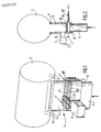
- the assembly represented in FIG. 1 comprises an injection block, indicated generally by reference 1, and a hollow envelope intended to be filled with expanded polyurethane, indicated generally by reference 2 and which can be intended to constitute a cushioning d '' headrest or any other cushioning part.
- the injection cylinder 3 is pierced at its lower part with a lumen 9 situated a little above the low point of the piston 5.
- This slot 9 allows the introduction of a sealing piston 10 of shape corresponding to the inner section of the cylinder 3 and intended to operate the scraping of the inner walls of this cylinder.
- the two components of the mixture, polyol and isocyanate, are brought under high pressure into the mixing chamber 7 and, under the effect of this pressure, the mixing is carried out, it flows through the conduit into the cylinder 3 closed at its base by the scraper piston 10.
- the propulsion piston 5 pulls up the scraper piston 10 which discharges, towards the orifice 4 of the enclosure 2, the mixture which has undergone a pre-expansion and is then in the form of beaten foam, that is to say very little liquid.
- the piston 5 continues to rise in the cylinder 3 and makes this foam penetrate into the envelope 2 where it continues and completes its expansion.
- the scraper piston 10 can, of course, remain in place at the orifice 4 to serve as a shutter, having a function of finishing the part.
- any injection process with two operating phases comprising a sealing step following a scraping step, by an auxiliary element, does not depart from the scope of the invention.
- the sections of the bore, of the piston and of the plate can be any but substantially identical.
Landscapes
- Casting Or Compression Moulding Of Plastics Or The Like (AREA)
- Processing And Handling Of Plastics And Other Materials For Molding In General (AREA)
- Injection Moulding Of Plastics Or The Like (AREA)
Abstract
L'invention a pour objet un procédé d'injection haute pression de mousse de polyuréthane dans une enveloppe creuse en utilisant des moyens du type comprenant une chambre de mélange des constituants de la mousse de polyuréthane, un cylindre communiquant avec ladite chambre, et ouvert à ses deux extrémités, l'une de ses extrémités débouchant dans l'orifice de l'enveloppe creuse et l'autre extrémité servant d'entrée à un piston agencé pour coulisser dans ledit cylindre et en refouler la mousse de polyuréthane dans ladite enveloppe. Selon l'invention, ledit cylindre (3) est sensiblement vertical, son extrémité supérieure débouche dans l'orifice de l'enveloppe creuse et il est d'un volume voisin de la moitié de celui délimité par l'enveloppe (2), et le mouvement du piston (5) dans ledit cylindre (3) est réglable en synchronisme avec le cycle de la tête de mélange.The subject of the invention is a process for high-pressure injection of polyurethane foam into a hollow envelope using means of the type comprising a chamber for mixing the constituents of polyurethane foam, a cylinder communicating with said chamber, and open to its two ends, one of its ends opening into the orifice of the hollow casing and the other end serving as an inlet for a piston arranged to slide in said cylinder and to push the polyurethane foam into said casing. According to the invention, said cylinder (3) is substantially vertical, its upper end opens into the orifice of the hollow envelope and it is of a volume close to half of that delimited by the envelope (2), and the movement of the piston (5) in said cylinder (3) is adjustable in synchronism with the cycle of the mixing head.
Description
La présente invention concerne des perfectionnements apportés aux procédés d'injection haute pression de mousse de polyuréthane dans une enveloppe creuse par un orifice prévu dans ladite enveloppe.The present invention relates to improvements made to the high pressure injection methods of polyurethane foam in a hollow envelope through an orifice provided in said envelope.
On connaît des têtes de coulée de mousse de polyuréthane permettant de mettre en oeuvre ces procédés. Le fonctionnement de ces têtes comprend généralement deux phases. La première phase est une phase de mélange, pendant laquelle au moins deux constituants de la mousse de polyuréthane, un polyol et un isocyanate, sont amenés sous haute pression dans une chambre de mélange, puis ce mélange s'écoule à travers un alésage vers une sortie, coïncidant éventuellement avec l'orifice d'une enveloppe à remplir. La seconde phase est une phase de recyclage et de nettoyage, pendant laquelle au moins un piston agit, d'une part, pour mettre en boucle sur lui-même chacun des deux circuits d'amenée des composants, et, d'autre part, pour racler les parois de l'alésage de la chambre de mélange, ceci afin de la nettoyer.Polyurethane foam pouring heads are known which make it possible to implement these methods. The operation of these heads generally comprises two phases. The first phase is a mixing phase, during which at least two components of the polyurethane foam, a polyol and an isocyanate, are brought under high pressure into a mixing chamber, then this mixture flows through a bore to a outlet, possibly coinciding with the opening of an envelope to be filled. The second phase is a recycling and cleaning phase, during which at least one piston acts, on the one hand, to loop each of the two component supply circuits on itself, and, on the other hand, to scrape the walls of the mixing chamber bore in order to clean it.
Dans FR 81 06 162 est décrit aussi un procédé d'injection de mousse de polyuréthane du type défini plus haut, qui utilise une tête d'injection comprenant en outre des moyens pour amener sous ledit piston, avant l'étape d'évacuation, un organe de raclage des parois de l'alésage lorsque le piston coulisse vers la sortie de l'alésage, cet organe de raclage étant consitué par une plaquette dont les dimensions sont sensiblement égales aux dimensions de la section de l'alésage et de l'orifice, et comportant une ou plusieurs lèvres souples s'étendant continûment sur son périmètre.In FR 81 06 162 is also described a method of injecting polyurethane foam of the type defined above, which uses an injection head further comprising means for bringing under said piston, before the evacuation step, a scraper member of the bore walls when the piston slides towards the outlet of the bore, this scraper member being constituted by a plate whose dimensions are substantially equal to the dimensions of the section of the bore and the orifice , and comprising one or more flexible lips extending continuously around its perimeter.
Dans ce procédé, la mousse de polyuréthane est coulé en phase liquide dans l'enveloppe creuse à l'intérieur de laquelle s'opère l'expansion, ou moussage, in situ, l'enveloppe étant conformée par un moule extérieur.In this process, the polyurethane foam is poured in the liquid phase into the hollow envelope inside which the expansion, or foaming, takes place, in situ, the envelope being shaped by an external mold.
Pour assurer la meilleure étanchéité possible, la paroi de l'enveloppe doit comporter, non seulement, un tissu ordinaire mais en plus une barrière pouvant être une mousse tranchée et la fabrication de l'enveloppe est coûteuse et assez délicate.To ensure the best possible seal, the wall of the envelope must include, not only, an ordinary fabric but in addition a barrier which can be a cut foam and the manufacture of the envelope is expensive and quite delicate.
La présente invention vise à simplifier cette fabrication an évitant d'avoir à doter l'enveloppe creuse de moyens particuliers d'étanchéité, ou tout au moins d'en simplifier les caractéristiques.The present invention aims to simplify this manufacture by avoiding having to provide the hollow envelope with special sealing means, or at least simplifying the characteristics.
A cet effet, l'invention prévoit d'injecter dans l'enveloppe, non plus un mélange de mousse liquide, mais un mélange de mousse en phase d'expansion, c'est-à-dire crêmeux, à l'état de mousse battue, et de laisser cette mousse achever son expansion dans l'enveloppe. Cette mousse n'ayant pas tendance à mouiller la paroi de l'enveloppe, aucun moyen d'étanchéité n'est plus nécessaire, ou du moins peut-il être très sommaire.To this end, the invention provides for injecting into the envelope, no longer a mixture of liquid foam, but a mixture of foam in the expansion phase, that is to say creamy, in the foam state. beaten, and allow this foam to complete its expansion in the envelope. Since this foam does not tend to wet the wall of the envelope, no sealing means is no longer necessary, or at least it can be very basic.
Pour la mise en oeuvre de ce procédé, l'invention prévoit l'introduction de polyuréthane dans l'enveloppe par l'intermédiaire d'un cylindre de volume voisin de la moitié de celui de l'enveloppe, dans lequel débouche la tête d'injection et qui est parcouru par un piston dont le mouvement est synchronisé avec le cycle de la tête de mélange pour que la mousse de polyuréthane subisse la préexpansion voulue avant d'être refoulée dans l'enveloppe, maintenue à l'intérieur d'un moule de conformation.For the implementation of this process, the invention provides for the introduction of polyurethane into the casing by means of a cylinder with a volume close to half that of the casing, into which the head opens. injection and which is traversed by a piston whose movement is synchronized with the cycle of the mixing head so that the polyurethane foam undergoes the desired pre-expansion before being discharged into the envelope, kept inside a mold of conformation.
A titre nullement limitatif, on a représenté au dessin annexé un exemple de réalisation de l'invention, dessin sur lequel
- La figure 1 est une vue schématique en perspective de la tête d'injection et de l'enveloppe à remplir, et
- La figure 2 est une vue en coupe transversale de l'ensemble de la figure 1.
- FIG. 1 is a schematic perspective view of the injection head and of the envelope to be filled, and
- Figure 2 is a cross-sectional view of the assembly of Figure 1.
L'ensemble représenté à la figure 1 comporte un bloc d'injection, indiqué globalement par le repère 1, et une enveloppe creuse destinée à être remplie de polyuréthane expansé, indiquée globalement par le repère 2 et qui peut être destinée à constituer une matelassure d'appui-tête ou tout autre pièce de coussinage.The assembly represented in FIG. 1 comprises an injection block, indicated generally by reference 1, and a hollow envelope intended to be filled with expanded polyurethane, indicated generally by
Le bloc d'injection 1 comporte un cylindre d'injection 3 vertical dont l'orifice supérieur 4 est engagé dans une ouverture de forme correspondante ménagée dans le fond de l'enveloppe 2. Le bloc 1 comprend également un piston 5 mû par des moyens hydrauliques, électromécaniques ou mécaniques (non représentés) pour coulisser dans le cylindre 3 entre le point haut, adjacent à l'orifice 4, et un point bas, orifice inférieur 6 de ce cylindre 3. Le bloc 1 comporte, en outre, une tête de mélange 7, de structure classique, débitant le mélange dans le cylindre 3 par l'intermédiaire du conduit 8.The injection block 1 comprises a
Le cylindre d'injection 3 est percé à sa partie inférieure d'une lumière 9 située un peu au-dessus du point bas du piston 5. Cette fente 9 permet l'introduction d'un piston d'étanchéité 10 de forme correspondant à la section intérieure du cylindre 3 et destiné à opérer le raclage des parois intérieures de ce cylindre.The
Le déroulement du procédé selon l'invention est le suivant.The procedure for the process according to the invention is as follows.
Comme on le sait, le procédé se déroule en deux phases. La première phase est la phase de coulée. Le piston de propulsion 5 étant en position basse, un piton de raclage 10 a été introduit dans le cylindre 3 par la lumière 9 et se trouve alors en contact sur la face d'extrémité supérieure du piston 5, la lumière étant obturée.As is known, the process takes place in two phases. The first phase is the casting phase. The
Les deux composants du mélange, polyol et isocyanate, sont amenés sous haute pression dans la chambre de mélange 7 et, sous l'effet de cette pression, le mélange est effectué, il s'écoule par le conduit dans le cylindre 3 obturé à sa base par le piston racleur 10. Au bout d'un très court instant, quelques secondes, le piston de propulsion 5 entraîne vers le haut le piston racleur 10 qui refoule, vers l'orifice 4 de l'enceinte 2, le mélange qui a subi une préexpansion et se trouve alors à l'état de mousse battue, c'est-à-dire très peu liquide. Le piston 5 poursuit sa remontée dans le cylindre 3 et fait pénétrer cette mousse dans l'enveloppe 2 où elle poursuit et achève son expansion. Le piston racleur 10 peut, bien entendu, demeurer en place à l'orifice 4 pour servir d'obturateur, ayant une fonction de finition de la pièce.The two components of the mixture, polyol and isocyanate, are brought under high pressure into the mixing chamber 7 and, under the effect of this pressure, the mixing is carried out, it flows through the conduit into the
Bien entendu les formes de réalisation et de mise en oeuvre décrites ci-dessus ne sont pas restrictives, et tout procédé d'injection à deux phases de fonctionnement comportant une étape d'obturation faisant suite à une étape de raclage, par un élément auxiliaire, ne sort pas du cadre de l'invention. En particulier, les sections de l'alésage, du piston et de la plaquette peuvent être quelconques mais sensiblement identiques.Of course, the embodiments and implementation described above are not restrictive, and any injection process with two operating phases comprising a sealing step following a scraping step, by an auxiliary element, does not depart from the scope of the invention. In particular, the sections of the bore, of the piston and of the plate can be any but substantially identical.
Claims (1)
Applications Claiming Priority (2)
| Application Number | Priority Date | Filing Date | Title |
|---|---|---|---|
| FR8610456A FR2601622B1 (en) | 1986-07-18 | 1986-07-18 | METHOD FOR INJECTING POLYURETHANE FOAM INTO A HOLLOW ENVELOPE, ESPECIALLY A VEHICLE HEADREST, AND MEANS FOR CARRYING OUT SAID METHOD |
| FR8610456 | 1986-07-18 |
Publications (2)
| Publication Number | Publication Date |
|---|---|
| EP0253733A1 true EP0253733A1 (en) | 1988-01-20 |
| EP0253733B1 EP0253733B1 (en) | 1991-05-29 |
Family
ID=9337541
Family Applications (1)
| Application Number | Title | Priority Date | Filing Date |
|---|---|---|---|
| EP87401663A Expired - Lifetime EP0253733B1 (en) | 1986-07-18 | 1987-07-15 | Apparatus for injecting polyurethane foam into a hollow envelope, especially of a head support in a vehicle |
Country Status (7)
| Country | Link |
|---|---|
| US (1) | US4830793A (en) |
| EP (1) | EP0253733B1 (en) |
| CA (1) | CA1327260C (en) |
| DE (1) | DE3770357D1 (en) |
| ES (1) | ES2025181B3 (en) |
| FR (1) | FR2601622B1 (en) |
| PT (1) | PT85341B (en) |
Families Citing this family (7)
| Publication number | Priority date | Publication date | Assignee | Title |
|---|---|---|---|---|
| JPH01135625A (en) * | 1987-11-20 | 1989-05-29 | Tokai Chem Ind Ltd | Molding of skin for expansion molded form with skin |
| US5000895A (en) * | 1990-08-08 | 1991-03-19 | Chrysler Corporation | Method for preventing plastic from hardening in a dispenser tip |
| US5273190A (en) * | 1992-07-27 | 1993-12-28 | Lund William J | Quick shot single barrel dispensing system |
| ES2121648B1 (en) * | 1995-01-31 | 2000-01-16 | Alcala Fibras | SPILL CYLINDER FOR FOAMING TABLES USED IN THE MANUFACTURE OF POLYURETHANE FOAM. |
| US7621238B2 (en) * | 2005-11-23 | 2009-11-24 | Bradford White Corporation | Water heater and system for insulating same |
| US9457698B2 (en) | 2014-02-27 | 2016-10-04 | Nissan North America, Inc. | Headrest support rod and method of making a headrest |
| US10179433B2 (en) * | 2017-03-02 | 2019-01-15 | Ford Global Technologies, Llc | Method of forming a headrest assembly |
Citations (4)
| Publication number | Priority date | Publication date | Assignee | Title |
|---|---|---|---|---|
| CH342749A (en) * | 1955-06-21 | 1959-11-30 | Basf Ag | Process for the production of moldings, packaging and insulation from foamed synthetic resins |
| DE2406041A1 (en) * | 1974-02-08 | 1975-09-04 | Jung Werke Gmbh | Foaming spaces between door architrave and walls - rendering foaming plastics material more viscous by introduction of additional foaming agent having a low boiling pt |
| EP0061972A1 (en) * | 1981-03-27 | 1982-10-06 | Etablissements TREVES | Polyurethane injection heads and methods of injection into a hollow envelope, especially of a head support |
| EP0094375A1 (en) * | 1982-05-06 | 1983-11-16 | Secans Ag | Method and mould for the manufacture of elastic shoe soles |
Family Cites Families (17)
| Publication number | Priority date | Publication date | Assignee | Title |
|---|---|---|---|---|
| US329712A (en) * | 1885-11-03 | Mvxntor | ||
| US2314639A (en) * | 1938-12-17 | 1943-03-23 | Monolith Portland Cement Compa | Cement sack |
| US2236727A (en) * | 1939-01-07 | 1941-04-01 | Calbar Paint & Varnish Company | Plastic material dispenser |
| US2569928A (en) * | 1949-10-03 | 1951-10-02 | Gonzalez Carlos | Apparatus for filling tubular receptacles with plural materials |
| US3140735A (en) * | 1962-01-19 | 1964-07-14 | Windle Engineering Company Inc | Horizontal bagging machine and lift |
| US3273760A (en) * | 1962-11-06 | 1966-09-20 | Continental Can Co | Container with expelling means for use in manned space ships |
| US3424827A (en) * | 1963-12-05 | 1969-01-28 | Sinclair Koppers Co | Process and apparatus for making shaped cellular articles from expandable thermoplastic resins |
| CH424222A (en) * | 1965-08-24 | 1966-11-15 | Gosta Trading Ltd | Process for the production of flexible, elastic moldings from foamable plastic, and device for carrying out the process |
| US3599282A (en) * | 1969-04-02 | 1971-08-17 | Goodyear Tire & Rubber | Apparatus for molding foam articles |
| BE779971R (en) * | 1971-04-10 | 1972-06-16 | Krauss Maffei Ag | APPARATUS FOR PRIMING AND PREPARING A MIXTURE OF TWO OR SEVERAL SYNTHETIC CONSTITUENTS IN THE MOLDING CAVITY OF A |
| GB1428968A (en) * | 1972-05-12 | 1976-03-24 | Kenrick & Sons Ltd | Methods of foam filling a tyre of a vehicle wheel and vehicle wheels with tyres so filled |
| FR2221092B1 (en) * | 1973-02-12 | 1976-09-10 | Palau Alfred | |
| US4030643A (en) * | 1975-12-11 | 1977-06-21 | Voplex Corporation | Contents-conserving plunger for cartridge |
| DE2612812C3 (en) * | 1976-03-25 | 1983-05-26 | Bayer Ag, 5090 Leverkusen | Mixing head for mixing at least two components which form foam when they react |
| DE2815460C3 (en) * | 1978-04-10 | 1981-09-24 | Elastogran Maschinenbau GmbH, 2844 Lemförde | Mixing device for multi-component plastics, especially polyurethane |
| DE2922312A1 (en) * | 1979-05-31 | 1981-03-26 | Civag AG für Verpackungsforschung, Herisau | FILLING DEVICE FOR INTAKING PRE-FOAMED, RE-EXPANDABLE, THERMOPLASTIC PLASTICS IN MOLDS FOR THE PRODUCTION OF MOLDED BODIES |
| DE2927115C2 (en) * | 1979-07-05 | 1986-04-17 | S.I.C.A.M. Societa Italiana Cuscini a Molle, Turin/Turino | Process for the production of upholstered seat parts, in particular backrests for motor vehicles |
-
1984
- 1984-07-17 US US07/075,834 patent/US4830793A/en not_active Expired - Fee Related
-
1986
- 1986-07-18 FR FR8610456A patent/FR2601622B1/en not_active Expired
-
1987
- 1987-07-15 ES ES87401663T patent/ES2025181B3/en not_active Expired - Lifetime
- 1987-07-15 CA CA000542240A patent/CA1327260C/en not_active Expired - Fee Related
- 1987-07-15 DE DE8787401663T patent/DE3770357D1/en not_active Expired - Fee Related
- 1987-07-15 EP EP87401663A patent/EP0253733B1/en not_active Expired - Lifetime
- 1987-07-16 PT PT85341A patent/PT85341B/en not_active IP Right Cessation
Patent Citations (4)
| Publication number | Priority date | Publication date | Assignee | Title |
|---|---|---|---|---|
| CH342749A (en) * | 1955-06-21 | 1959-11-30 | Basf Ag | Process for the production of moldings, packaging and insulation from foamed synthetic resins |
| DE2406041A1 (en) * | 1974-02-08 | 1975-09-04 | Jung Werke Gmbh | Foaming spaces between door architrave and walls - rendering foaming plastics material more viscous by introduction of additional foaming agent having a low boiling pt |
| EP0061972A1 (en) * | 1981-03-27 | 1982-10-06 | Etablissements TREVES | Polyurethane injection heads and methods of injection into a hollow envelope, especially of a head support |
| EP0094375A1 (en) * | 1982-05-06 | 1983-11-16 | Secans Ag | Method and mould for the manufacture of elastic shoe soles |
Also Published As
| Publication number | Publication date |
|---|---|
| ES2025181B3 (en) | 1992-03-16 |
| FR2601622B1 (en) | 1988-12-02 |
| US4830793A (en) | 1989-05-16 |
| DE3770357D1 (en) | 1991-07-04 |
| CA1327260C (en) | 1994-03-01 |
| PT85341B (en) | 1993-07-30 |
| FR2601622A1 (en) | 1988-01-22 |
| EP0253733B1 (en) | 1991-05-29 |
| PT85341A (en) | 1988-07-29 |
Similar Documents
| Publication | Publication Date | Title |
|---|---|---|
| EP0006381A1 (en) | Device for moulding foamed plastic articles | |
| EP1064205B1 (en) | Airless dispensing device | |
| CA1291074C (en) | Liquid substances or solid and liquid material processing device | |
| FR2779040A1 (en) | DEVICE FOR DISPENSING PASTE PRODUCT, ESPECIALLY COSMETIC, AND METHOD FOR MANUFACTURING THE DEVICE | |
| EP0253733B1 (en) | Apparatus for injecting polyurethane foam into a hollow envelope, especially of a head support in a vehicle | |
| FR2716135A1 (en) | Injection moulding machine | |
| EP0545758B1 (en) | Espresso coffee machine | |
| FR2463692A1 (en) | OPENING ROOF STRUCTURE OF VEHICLE | |
| FR2708512A1 (en) | Delimited insertion process of a decoration in a thermoplastic support. | |
| LU80473A1 (en) | METHOD FOR MANUFACTURING A SUN VISOR, PARTICULARLY FOR A MOTOR VEHICLE, OF THE TYPE INCLUDING A MIRROR | |
| EP0072746B1 (en) | Hand held spraygun for dispersing a plant treatment liquid | |
| FR2912716A1 (en) | Brake fluid reservoir for motor vehicle, has compartment set in internal cavity and provided with opening to cooperate with filling tool introduced in cavity to seal compartment, where opening is formed in inner wall at interior of cavity | |
| EP1066142A1 (en) | Facility for producing latex objects such as pillows | |
| EP0341127A2 (en) | High-frequency moulding method and apparatus for liquid plastic material | |
| FR2502542A1 (en) | IMPROVEMENTS ON POLYURETHANE INJECTION HEADS AND INJECTION METHODS IN A HOLLOW ENVELOPE, IN PARTICULAR OF A HEADREST | |
| FR2517359A1 (en) | DEVICE FOR CONTROLLING A SAFETY VALVE PROVIDED BELOW AN ACTIVATION PUMP IN A WELL FOR HYDROCARBON PRODUCTION | |
| FR2458381A1 (en) | Mould for plastic cellular objects - has means of sealing filling inlet and applying partial vacuum during polymerisation | |
| FR2711076A1 (en) | Watertight and elastically deformable device for the removal of the residual layer. | |
| FR2810634A1 (en) | DOSING DEVICE FOR LIQUID OR PASTY PRODUCTS | |
| FR2616085A1 (en) | Device for delivering a pressurised mixture of at least two fluids | |
| FR2597833A1 (en) | Method and device for heat-sealing trays with gaseous internal atmosphere | |
| FR2601706A1 (en) | Method for anchoring a foundation pile in the ground and device for the implementation of this method | |
| FR2545000A1 (en) | Device for the reactive mixing of chemical products | |
| FR2717988A1 (en) | Mfg. appts. for ice-cream and frozen desserts | |
| FR2845836A1 (en) | Sealed joint for cables passing through bulkhead includes internal cavity filled with setting liquid after installation to secure cables |
Legal Events
| Date | Code | Title | Description |
|---|---|---|---|
| PUAI | Public reference made under article 153(3) epc to a published international application that has entered the european phase |
Free format text: ORIGINAL CODE: 0009012 |
|
| AK | Designated contracting states |
Kind code of ref document: A1 Designated state(s): DE ES FR GB IT |
|
| 17P | Request for examination filed |
Effective date: 19880718 |
|
| 17Q | First examination report despatched |
Effective date: 19890213 |
|
| GRAA | (expected) grant |
Free format text: ORIGINAL CODE: 0009210 |
|
| AK | Designated contracting states |
Kind code of ref document: B1 Designated state(s): DE ES FR GB IT |
|
| REF | Corresponds to: |
Ref document number: 3770357 Country of ref document: DE Date of ref document: 19910704 |
|
| ITF | It: translation for a ep patent filed |
Owner name: CALVANI SALVI E VERONELLI S.R.L. |
|
| GBT | Gb: translation of ep patent filed (gb section 77(6)(a)/1977) | ||
| PLBI | Opposition filed |
Free format text: ORIGINAL CODE: 0009260 |
|
| 26 | Opposition filed |
Opponent name: ELASTOGRAN POLYURETHANE GMBH Effective date: 19911119 |
|
| REG | Reference to a national code |
Ref country code: ES Ref legal event code: FG2A Ref document number: 2025181 Country of ref document: ES Kind code of ref document: B3 |
|
| PLBN | Opposition rejected |
Free format text: ORIGINAL CODE: 0009273 |
|
| STAA | Information on the status of an ep patent application or granted ep patent |
Free format text: STATUS: OPPOSITION REJECTED |
|
| 27O | Opposition rejected |
Effective date: 19930426 |
|
| PGFP | Annual fee paid to national office [announced via postgrant information from national office to epo] |
Ref country code: GB Payment date: 19950710 Year of fee payment: 9 |
|
| PGFP | Annual fee paid to national office [announced via postgrant information from national office to epo] |
Ref country code: ES Payment date: 19950720 Year of fee payment: 9 |
|
| PGFP | Annual fee paid to national office [announced via postgrant information from national office to epo] |
Ref country code: DE Payment date: 19950722 Year of fee payment: 9 |
|
| PGFP | Annual fee paid to national office [announced via postgrant information from national office to epo] |
Ref country code: FR Payment date: 19950727 Year of fee payment: 9 |
|
| PG25 | Lapsed in a contracting state [announced via postgrant information from national office to epo] |
Ref country code: GB Effective date: 19960715 |
|
| PG25 | Lapsed in a contracting state [announced via postgrant information from national office to epo] |
Ref country code: ES Free format text: LAPSE BECAUSE OF EXPIRATION OF PROTECTION Effective date: 19960716 |
|
| GBPC | Gb: european patent ceased through non-payment of renewal fee |
Effective date: 19960715 |
|
| PG25 | Lapsed in a contracting state [announced via postgrant information from national office to epo] |
Ref country code: FR Effective date: 19970328 |
|
| PG25 | Lapsed in a contracting state [announced via postgrant information from national office to epo] |
Ref country code: DE Effective date: 19970402 |
|
| REG | Reference to a national code |
Ref country code: FR Ref legal event code: ST |
|
| REG | Reference to a national code |
Ref country code: ES Ref legal event code: FD2A Effective date: 19990601 |
|
| PG25 | Lapsed in a contracting state [announced via postgrant information from national office to epo] |
Ref country code: IT Free format text: LAPSE BECAUSE OF NON-PAYMENT OF DUE FEES;WARNING: LAPSES OF ITALIAN PATENTS WITH EFFECTIVE DATE BEFORE 2007 MAY HAVE OCCURRED AT ANY TIME BEFORE 2007. THE CORRECT EFFECTIVE DATE MAY BE DIFFERENT FROM THE ONE RECORDED. Effective date: 20050715 |