EP0253689B1 - Ejecteur à rotation induite - Google Patents
Ejecteur à rotation induite Download PDFInfo
- Publication number
- EP0253689B1 EP0253689B1 EP87401133A EP87401133A EP0253689B1 EP 0253689 B1 EP0253689 B1 EP 0253689B1 EP 87401133 A EP87401133 A EP 87401133A EP 87401133 A EP87401133 A EP 87401133A EP 0253689 B1 EP0253689 B1 EP 0253689B1
- Authority
- EP
- European Patent Office
- Prior art keywords
- compartment
- annular
- fluid
- zone
- driving fluid
- Prior art date
- Legal status (The legal status is an assumption and is not a legal conclusion. Google has not performed a legal analysis and makes no representation as to the accuracy of the status listed.)
- Expired
Links
- 239000012530 fluid Substances 0.000 claims abstract description 170
- 239000000203 mixture Substances 0.000 claims abstract description 47
- 238000000034 method Methods 0.000 claims abstract description 7
- 230000006835 compression Effects 0.000 claims description 16
- 238000007906 compression Methods 0.000 claims description 16
- 230000003247 decreasing effect Effects 0.000 claims description 12
- 239000007788 liquid Substances 0.000 claims description 12
- 230000007423 decrease Effects 0.000 description 8
- 238000010586 diagram Methods 0.000 description 6
- 241000287107 Passer Species 0.000 description 4
- 238000013459 approach Methods 0.000 description 2
- 230000000694 effects Effects 0.000 description 2
- 230000000630 rising effect Effects 0.000 description 2
- 230000001609 comparable effect Effects 0.000 description 1
- 238000010790 dilution Methods 0.000 description 1
- 239000012895 dilution Substances 0.000 description 1
- 238000004821 distillation Methods 0.000 description 1
- 239000000314 lubricant Substances 0.000 description 1
- 238000004519 manufacturing process Methods 0.000 description 1
- 238000005086 pumping Methods 0.000 description 1
- 230000002040 relaxant effect Effects 0.000 description 1
- 239000007787 solid Substances 0.000 description 1
- 230000003068 static effect Effects 0.000 description 1
Images

Classifications
-
- F—MECHANICAL ENGINEERING; LIGHTING; HEATING; WEAPONS; BLASTING
- F04—POSITIVE - DISPLACEMENT MACHINES FOR LIQUIDS; PUMPS FOR LIQUIDS OR ELASTIC FLUIDS
- F04F—PUMPING OF FLUID BY DIRECT CONTACT OF ANOTHER FLUID OR BY USING INERTIA OF FLUID TO BE PUMPED; SIPHONS
- F04F5/00—Jet pumps, i.e. devices in which flow is induced by pressure drop caused by velocity of another fluid flow
- F04F5/02—Jet pumps, i.e. devices in which flow is induced by pressure drop caused by velocity of another fluid flow the inducing fluid being liquid
- F04F5/04—Jet pumps, i.e. devices in which flow is induced by pressure drop caused by velocity of another fluid flow the inducing fluid being liquid displacing elastic fluids
- F04F5/06—Jet pumps, i.e. devices in which flow is induced by pressure drop caused by velocity of another fluid flow the inducing fluid being liquid displacing elastic fluids of rotary type
-
- F—MECHANICAL ENGINEERING; LIGHTING; HEATING; WEAPONS; BLASTING
- F04—POSITIVE - DISPLACEMENT MACHINES FOR LIQUIDS; PUMPS FOR LIQUIDS OR ELASTIC FLUIDS
- F04F—PUMPING OF FLUID BY DIRECT CONTACT OF ANOTHER FLUID OR BY USING INERTIA OF FLUID TO BE PUMPED; SIPHONS
- F04F5/00—Jet pumps, i.e. devices in which flow is induced by pressure drop caused by velocity of another fluid flow
- F04F5/42—Jet pumps, i.e. devices in which flow is induced by pressure drop caused by velocity of another fluid flow characterised by the input flow of inducing fluid medium being radial or tangential to output flow
Definitions
- the present invention relates to an ejection method and device for compressing and / or pumping a fluid.
- the device according to the present invention is compact.
- the ejectors represent a simple and inexpensive means in terms of investments for compressing a fluid.
- the ejection devices according to the prior art have a certain number of drawbacks which limit their possibilities of application.
- the device according to the invention aims to overcome the drawbacks of the devices known in the prior art.
- the present invention relates to a device for compressing a fluid by expansion of a working fluid comprising a first compartment in which the working fluid circulates, a second compartment in which the fluid to be compressed circulates, a third compartment in which circulates mixing the working fluid and the fluid to be compressed, said mixture coming from a mixing compartment connected to the third compartment and to the first and second compartments.
- the device according to the invention is characterized in particular in that the mixing compartment has an annular shape and in that the first and second compartments are connected to the mixing compartment by passages adapted to introduce in a substantially tangential manner the working fluid and the fluid to be compressed in the mixing compartment.
- the annular compartment which has an average outside diameter and an average inside diameter delimiting it, may be provided so that the ratio of the average outside diameter of the annular zone to the difference between said average outside diameter and said average inside diameter is at least equal to 5.
- the second compartment for distributing the fluid to be compressed may comprise a circular crown pierced with channels opening onto the annular compartment, these channels possibly being regularly spaced around the periphery of said annular compartment, and being able to be curved so as to introduce the fluid to be compressed with a substantially tangential speed in the annular zone.
- the third compartment for compressing the mixture of the two fluids from said annular compartment may itself include an annular space in which will be placed rectifier blades adapted to gradually cancel the tangential speed component of the mixture by raising the pressure.
- the first compartment for distributing the working fluid may comprise a series of converging nozzles opening into the annular compartment, the nozzles preferably being regularly spaced around the periphery of the annular compartment and being inclined so as to introduce the working fluid with a substantially tangential speed in the annular compartment.
- the first motor fluid distribution compartment may comprise a circular crown pierced with channels opening onto the annular compartment, the channels preferably being regularly spaced around the periphery of the annular compartment and having a convergent shape so as to communicate an increasing speed to the motor fluid. , and further having a curved shape so as to introduce the fluid to be compressed with a speed substantially tangential to the annular compartment.
- the first compartment for distributing the working fluid may comprise an annular zone comprised between two conical surfaces whose generatrices may form a different angle with the axis of the device so as to create said converging annular zone into which the working fluid will be introduced by an inlet tangential at the level of the largest section and will travel with increasing tangential speed to the smallest section which communicates with the annular compartment.
- the third compartment for compressing the mixture of the two fluids coming from the annular compartment may itself include an annular zone comprised between two conical surfaces whose generatrices may form a different angle with the axis of the device, so as to create said zone divergent ring in which the mixture of the two fluids coming from the annular compartment opens at the level of the smallest section and circulates with a decreasing tangential speed to the largest section.
- the third compression compartment may include a first space between two surfaces placed substantially transverse to the axis of the device in which the mixture can circulate with a decreasing tangential speed while being evacuated at the periphery of said first space, said first space being followed by a second space also comprised between two surfaces placed in a transverse manner relatively to the axis of the device in which the mixture is brought back towards the axis of the device while circulating with a decreasing tangential speed, the second space could be fitted with straightening blades allowing the tangential speed of the mixture to be gradually canceled.
- the angle of introduction of the working fluid into the first distribution compartment of the working fluid may be modified when the flow rate of said working fluid varies, so as to keep the tangential speed of circulation of the working fluid substantially constant.
- the device according to the invention can be used to compress a gas or a vapor or to compress a liquid.
- the working fluid may consist of a gas or a vapor, or even a liquid.
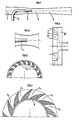
- FIG. 1 illustrates the principle of an ejection device according to the prior art.
- the fluid to be compressed arrives via the suction pipe 1.
- the compression work is provided by a working fluid which arrives through line 2.
- the fluid to be compressed and the working fluid can thus be admitted into the mixing zone 4 at the same pressure level.
- the mixing zone 4 there is an exchange of momentum between the working fluid and the fluid to be compressed and at the exit from the mixing zone the speed field can be considered to be substantially uniform.
- the device made it possible to compress the fluid arriving via line 1 by partially relaxing the working fluid arriving via line 2.
- Such a device can be used with different liquid or gaseous fluids.
- An example of the use of a gas-gas ejectocompressor is described in the French patent application registered on June 28, 1985 under the number 85/09844 (EP-A 0 210 888), this application describing the compression by such a device. overhead steam from distillation.
- the friction losses can represent from 5 to 15% of the kinetic energy of the mixture. These losses are linked to the heterogeneity of the speed field at the inlet of the mixer and to the fact that the mixer must have a sufficient length to homogenize this speed field.
- the generator of the diffuser must not make an angle with the axis greater than approximately 7 ° , because of the risks of instability of the flow and therefore the length of the diffuser is important compared to the diameter. This results in losses reaching 15 to 60% of the kinetic energy of the mixture, depending on the ratio of the sections and the technique adopted.
- the fluid to be compressed which arrives through the nozzle 6 opens at the center of the vortex formed by the working fluid.
- FIG. 3 The principle of the device according to the invention is illustrated very schematically in FIG. 3.
- the difference between the mean outside diameter of the annular zone (A) and the mean internal diameter of the annular zone (A) is reduced compared to the mean external diameter, the ratio of the mean external diameter of the annular zone (A) to the difference between the mean external diameter and the mean internal diameter of the annular zone (A) being at least equal but preferably greater than 5.
- the respective positions of the first and second zones (I) and (II) can be changed.
- first zone (I) for introducing the working fluid can be placed inside said annular space and the second zone (II) for introducing the low pressure fluid to be compressed outside said annular space .
- zones (I) and (II) are placed at different diameters.
- the first and second zones (I) and (II) may even be located on the same side of the annular zone (A), as shown in the following exemplary embodiments.
- a first embodiment of the device according to the invention is represented by the diagrams of FIGS. 4A and 4B.
- FIG. 4A represents a longitudinal section of the device along the plane A-A indicated in FIG. 4B and in FIG. 4B a transverse section of the device by the plane B-B indicated in FIG. 4A.
- the low pressure fluid to be compressed arrives via the conduit 7. It is then distributed through a circular crown C which in this embodiment represents the second distribution zone (II).
- this circular ring it is distributed along a series of channels such as C1, C2, C3, C4 arranged substantially radially and placed at regular intervals. These channels are convergent, that is to say that their section decreases towards the periphery of said circular ring, so as to communicate to the low pressure fluid to be compressed at an increasing speed and are curved so as to introduce the low pressure fluid to be compressed with a substantially tangential speed in the annular zone (A).
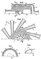
- the working fluid arrives through a series of converging nozzles such as T1, T2, T3.
- these nozzles T represent the first zone (I) for distributing the working fluid.
- the inlet nozzles T of the working fluid are convergent, so as to impart an increasing speed to the working fluid, while reducing its pressure, so as to bring it to a level lower than that of the fluid to be compressed and are inclined so introducing the working fluid with a tangential speed into the annular zone (A).
- the orifices located on either side of the annular zone (A) through which the channels such as C1, C2, and C3 open respectively and the nozzles such as T1, T2 and T3 are placed opposite.
- the working fluid and the low pressure fluid to be compressed are mixed in the annular zone (A) and the mixture of these two fluids circulates with a gyratory movement with an average speed substantially uniform over the entire circumference of the annular space (A) and over the entire passage section of the annular space (A).
- the blading forms with the longitudinal axis 19 of the device an angle D3 close to 90,. This angle then gradually decreases as it approaches a zero value, so as to gradually reduce the tangential speed of the mixture.
- the mixture is thus compressed. It is then evacuated through the space ED1 towards the evacuation duct 8.
- the first, second and third zones (I), (II) and (III) can be made with geometries different, while being in accordance with the principle of the invention.
- the circular crown C for distributing the low pressure fluid to be compressed may have an internal diameter different from the inlet duct 7.
- the width of said circular crown which is presented according to the diagram in the figure is reduced. 5, which simplifies the implementation.
- the reference 20 in FIG. 5 represents the internal diameter of the circular crown C and the reference 21 designates the dotted line corresponding to the trace of the inlet duct 7.
- FIGS. 4A, 4B and 4C The geometry shown diagrammatically in FIGS. 4A, 4B and 4C is particularly advantageous when the low pressure fluid to be compressed is admitted into the annular space (A) with a relatively low speed.
- this speed it is preferable to communicate this speed gradually so as to avoid a relatively large pressure drop on admission. This is achieved by gradually modifying the section of the channels such as C1, C2, C3, which implies a sufficient length of these channels and a relatively wide distribution ring.
- the low pressure fluid distribution ring can be produced either by hollowing out channels on a solid part, or by means of blades 22 making it possible to orient the fluid tangentially according to the diagram in FIG. 6.
- Another possibility consists in distributing the low pressure fluid to be compressed according to a series of nozzles regularly arranged like the channels such as C1, C2, C3 and inclined so as to cause the low pressure fluid to be compressed in the annular space (A) with tangential speed.
- the distribution of the working fluid in the first zone (I) can also be carried out in a different manner from that described above.
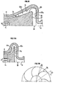
- the working fluid can be distributed through a circular ring such as that shown diagrammatically in FIG. 7.
- a circular ring such as that shown diagrammatically in FIG. 7.
- this circular ring it is distributed along a series of channels such as T10, T11, T12, T13, T14 arranged radially and placed at regular intervals.
- These channels are convergent, that is to say that their section decreases towards the inside of said circular ring so as to communicate to the working fluid an increasing speed and are curved so as to introduce the working fluid with a substantially tangential speed into the circular area (A).
- the internal diameter of the distribution crown can be greater than the external diameter of the annular zone (A) and the distribution crown can be offset in longitudinal position with respect to the annular zone (A), as shown in the diagram of embodiment of FIG. 8.
- the working fluid arrives tangentially through the opening 23. It joins the annular zone for mixing with the low pressure fluid through the curved annular zone 24.
- the intermediate annular zone 24 has a shape convergent, which increases the tangential speed of the working fluid.
- the reference CD1 designates the crown for distributing the working fluid which may preferably include fins.
- the low pressure fluid to be compressed arrives via the conduit 25. It is rotated in the distribution ring CD2 and mixes with the working fluid in the annular zone (A).
- This crown may preferably include fins.
- the first two distribution zones (I) and (II) are placed radially on the same side of the annular zone (A).
- a converging annular zone such as the intermediate annular zone 24 with a tangential inlet, can also replace the multi-nozzle system such as that shown in FIG. 5, or a distribution ring, such as that shown in FIG. 7.
- FIG. 9A Such an arrangement is shown in FIG. 9A.
- the working fluid arrives tangentially through the opening 10. It then passes into the annular zone 12 comprised between two conical surfaces of different angles, so as to create a converging annular zone in which the tangential speed of the working fluid increases due to the restriction of the cross section to the tangential flow of the working fluid.
- the device according to the invention has the advantage of being able to be used in a wide range of flow rates.
- the tangential speed in the area (1) of distribution of the working fluid can be modulated, unlike the longitudinal speed which results from the ratio of the flow rate to the passage section perpendicular to the axis of the device.
- a comparable effect can be obtained, not by modifying the angle of introduction of the intake duct 11, but by modifying the position of a flap which has the effect of reducing more or less the tangential speed of flow.
- the shutter 14 is an adjustable shutter which makes it possible to maintain the tangential speed constant, even when the flow of working fluid varies.
- This flap is raised when the flow of working fluid decreases, to compensate for the decrease in the speed with which the working fluid emerges in the annular space 12 through the opening 10 and lowered when the flow of working fluid increases to compensate for the increase in the speed with which the working fluid emerges in the annular space 12 through the opening 10.
- the device according to the invention can thus operate over a wide flow range.
- FIG. 9A the distribution of the fluid to compressing can be carried out substantially in the same way as that shown in FIGS. 4A and 4B.
- the flap 14 can rotate either around an axis substantially parallel to the axis of the device or around an axis perpendicular to the axis of the device. Finally, several flaps can be arranged so as to obtain a speed orientation effect better distributed over the periphery of the annular section.
- the third zone (III) for compressing the mixture formed in the annular zone (A) by the working fluid and the low pressure fluid may also have a configuration different from that which is shown in FIG. 4A.
- FIG. 10 Another example of the geometry of the third zone (III) is shown in FIG. 10.
- the working fluid mixes with the low pressure fluid which arrives through the conduit 15 in the annular space (A).
- the mixture of the two fluids flows in the annular space EA2 comprised between two substantially conical surfaces 13 and 26 whose generatrices form a different angle with the axis of the device, so as to create a divergent annular zone in which the mixture of two fluids coming from the annular zone (A) opens at the level of the smallest section and circulates with a decreasing tangential speed in the direction of the largest section.
- the annular zone EA2 is provided, over part of its length, with rectifier blades R2 intended to promote the slowing down of the tangential speed. These rectifier blades can be in certain cases omitted, in order to simplify the manufacture of an apparatus operating according to the principle of the device according to the invention.
- the mixture of the two fluids is then brought back towards the axis 19 of the device while circulating in the space ED2 comprised between two surfaces 27 and 28 placed in a manner substantially perpendicular to the axis of the device and is evacuated by the conduit 8.
- the angle formed by the generatrices of the conical surfaces between which the space EA2 is comprised with the axis 19 of the device is preferably variable and gradually increases along this axis considering the direction of circulation of the fluid.
- the working fluid mixes with the low pressure fluid which arrives through the conduit 17 in the annular space (A).
- the mixture of the two fluids flows in the space EA3 comprised between two surfaces placed substantially perpendicular to the axis 19 of the device and progressively connecting to the surfaces located on either side of the space annular (A).
- the mixture circulates with a decreasing tangential speed towards the periphery.
- the space ED3 At the periphery of the space EA3 it opens onto the space ED3 in which it is brought back towards the axis 19 of the device, the space ED3 being between two surfaces placed in a manner substantially perpendicular to the axis 19 of the device.
- the ED3 space is provided with rectifier blades R3, the geometry of which in a front view is shown diagrammatically in FIG. 11 B.
- the angle formed at a point of the blade between the tangent to the surface of the blade and the radius from this point varied between a value close to 90, at the input (angle D1) and a value close to 0, at the output (angle D2), which makes it possible to gradually cancel the tangential speed.
- the device can be used with liquid, gaseous, or even multiphase two-phase fluids.
- the low pressure fluid to be compressed can be a gas or a vapor or in some cases a two-phase gas-liquid mixture.
- the working fluid can also be either a gas or a liquid.
- each of the fluids can be two-phase.
- the section of the annular zone, of the nozzles or of the channels which is possibly provided with the first zone (I) of distribution of the working fluid does not constantly decrease between the inlet and the outlet of the working fluid, but passes through a minimum , the sonic neck being located at this minimum section, then growing again.
- the flow velocity can be subsonic or supersonic. If it is supersonic, the flow section in the third compression zone (III) must also go through a minimum by first decreasing, then gradually increasing.
Landscapes
- Engineering & Computer Science (AREA)
- Physics & Mathematics (AREA)
- Fluid Mechanics (AREA)
- Mechanical Engineering (AREA)
- General Engineering & Computer Science (AREA)
- Jet Pumps And Other Pumps (AREA)
- Saccharide Compounds (AREA)
- External Artificial Organs (AREA)
- Developing Agents For Electrophotography (AREA)
- Gas Separation By Absorption (AREA)
- Medicinal Preparation (AREA)
Priority Applications (1)
| Application Number | Priority Date | Filing Date | Title |
|---|---|---|---|
| AT87401133T ATE45207T1 (de) | 1986-05-22 | 1987-05-20 | Ejektor mit induzierter drehung. |
Applications Claiming Priority (2)
| Application Number | Priority Date | Filing Date | Title |
|---|---|---|---|
| FR8607444 | 1986-05-22 | ||
| FR8607444A FR2599093B1 (fr) | 1986-05-22 | 1986-05-22 | Ejecteur a rotation induite |
Publications (2)
| Publication Number | Publication Date |
|---|---|
| EP0253689A1 EP0253689A1 (fr) | 1988-01-20 |
| EP0253689B1 true EP0253689B1 (fr) | 1989-08-02 |
Family
ID=9335585
Family Applications (1)
| Application Number | Title | Priority Date | Filing Date |
|---|---|---|---|
| EP87401133A Expired EP0253689B1 (fr) | 1986-05-22 | 1987-05-20 | Ejecteur à rotation induite |
Country Status (10)
| Country | Link |
|---|---|
| US (1) | US4749336A (ro) |
| EP (1) | EP0253689B1 (ro) |
| JP (1) | JP2864123B2 (ro) |
| KR (1) | KR960008965B1 (ro) |
| AT (1) | ATE45207T1 (ro) |
| AU (1) | AU600943B2 (ro) |
| BR (1) | BR8702625A (ro) |
| DE (1) | DE3760396D1 (ro) |
| FR (1) | FR2599093B1 (ro) |
| IN (1) | IN169704B (ro) |
Families Citing this family (9)
| Publication number | Priority date | Publication date | Assignee | Title |
|---|---|---|---|---|
| FR2720122B1 (fr) * | 1994-05-20 | 1996-06-28 | Inst Francais Du Petrole | Pompe polyphasique bi-turbojets. |
| RU2162968C2 (ru) * | 1999-03-22 | 2001-02-10 | Курский государственный технический университет | Вихревой эжектор |
| US7794135B2 (en) * | 2004-11-05 | 2010-09-14 | Schlumberger Technology Corporation | Dry polymer hydration apparatus and methods of use |
| JP5030520B2 (ja) * | 2006-09-29 | 2012-09-19 | 富士フイルム株式会社 | 流体混合方法及びマイクロデバイス |
| US8807458B2 (en) * | 2009-04-29 | 2014-08-19 | King Saud University | Vortex-generating nozzle-end ring |
| DE102009047083C5 (de) * | 2009-11-24 | 2013-09-12 | J. Schmalz Gmbh | Druckluftbetriebener Unterdruckerzeuger oder Unterdruckgreifer |
| CN103339452B (zh) * | 2011-02-09 | 2016-01-20 | 开利公司 | 喷射器 |
| US9322400B2 (en) * | 2012-10-02 | 2016-04-26 | Ford Global Technologies, Llc | Jet pump with centralized nozzle |
| CN109966941A (zh) * | 2019-05-13 | 2019-07-05 | 江苏炬焰智能科技有限公司 | 碳酸泉混合器 |
Family Cites Families (14)
| Publication number | Priority date | Publication date | Assignee | Title |
|---|---|---|---|---|
| DE57884C (de) * | E. SCHÜRMANN in Riesa | Gebläse | ||
| FR25258E (fr) * | 1921-04-22 | 1923-01-23 | Procédé et appareils pour la compression des fluides gazeux | |
| US1612838A (en) * | 1925-04-09 | 1927-01-04 | Centrifix Corp | Draft-inducing means |
| GB362430A (en) * | 1929-08-30 | 1931-12-01 | Paul Lechler | Improvements in or relating to the production of emulsions |
| FR712885A (fr) * | 1930-04-22 | 1931-10-14 | Paul Lechler | Appareil mélangeur pour fluides |
| FR707360A (fr) * | 1930-12-10 | 1931-07-07 | Procédé et installation pour le traitement de liquides par des gaz | |
| FR1048869A (fr) * | 1950-10-13 | 1953-12-24 | Stamicarbon | Procédé et dispositif pour disperser ou pour dissoudre une substance dans un liquide |
| FR1150946A (fr) * | 1956-05-23 | 1958-01-22 | Fr D Etudes Et De Realisations | Thermo-soufflante statique |
| US3046732A (en) * | 1956-06-20 | 1962-07-31 | Research Corp | Method of energy exchange and apparatus for carrying out the same |
| US3371618A (en) * | 1966-02-18 | 1968-03-05 | Chambers John | Pump |
| US4074954A (en) * | 1976-02-27 | 1978-02-21 | Mobil Oil Corporation | Compressor |
| SU731220A1 (ru) * | 1978-10-11 | 1980-04-30 | Куйбышевский Ордена Трудового Красного Знамени Авиационный Институт Им.Академика С.П.Королева | Вихрева труба |
| US4409746A (en) * | 1981-02-05 | 1983-10-18 | Conoco Inc. | Vortex injection dredging apparatus and method |
| GB2149679A (en) * | 1983-11-14 | 1985-06-19 | Conoco Inc | Vortex eductor |
-
1986
- 1986-05-22 FR FR8607444A patent/FR2599093B1/fr not_active Expired - Lifetime
-
1987
- 1987-05-20 EP EP87401133A patent/EP0253689B1/fr not_active Expired
- 1987-05-20 AU AU73243/87A patent/AU600943B2/en not_active Ceased
- 1987-05-20 DE DE8787401133T patent/DE3760396D1/de not_active Expired
- 1987-05-20 AT AT87401133T patent/ATE45207T1/de not_active IP Right Cessation
- 1987-05-21 US US07/052,391 patent/US4749336A/en not_active Expired - Lifetime
- 1987-05-22 BR BR8702625A patent/BR8702625A/pt not_active IP Right Cessation
- 1987-05-22 KR KR1019870005076A patent/KR960008965B1/ko not_active Expired - Fee Related
- 1987-05-22 JP JP62125622A patent/JP2864123B2/ja not_active Expired - Fee Related
- 1987-07-02 IN IN477/MAS/87A patent/IN169704B/en unknown
Also Published As
| Publication number | Publication date |
|---|---|
| JP2864123B2 (ja) | 1999-03-03 |
| AU600943B2 (en) | 1990-08-30 |
| EP0253689A1 (fr) | 1988-01-20 |
| US4749336A (en) | 1988-06-07 |
| DE3760396D1 (en) | 1989-09-07 |
| KR960008965B1 (ko) | 1996-07-10 |
| KR870010904A (ko) | 1987-12-18 |
| FR2599093B1 (fr) | 1991-08-02 |
| FR2599093A1 (fr) | 1987-11-27 |
| BR8702625A (pt) | 1988-02-23 |
| JPS62285000A (ja) | 1987-12-10 |
| ATE45207T1 (de) | 1989-08-15 |
| IN169704B (ro) | 1991-12-14 |
| AU7324387A (en) | 1987-11-26 |
Similar Documents
| Publication | Publication Date | Title |
|---|---|---|
| FR2556054A1 (fr) | Diffuseur pour compresseur centrifuge | |
| BE1016382A3 (fr) | Dispositif d'injection de fluides a l'interieur d'un lit fluidifie rotatif. | |
| EP0239462B1 (fr) | Dispositif d'injection à vrille axialo centripète | |
| EP0253689B1 (fr) | Ejecteur à rotation induite | |
| FR2632215A1 (fr) | Dispositif de separation a tube a tourbillon | |
| FR2533977A1 (fr) | Roue centrifuge a plusieurs etages | |
| FR2675850A1 (fr) | Injecteur de carburant pour statoreacteur. | |
| EP0090729A1 (fr) | Dispositif de graissage et de refroidissement d'un palier inter-arbres d'une turbomachine | |
| EP1775441B1 (fr) | Dispositif de suralimentation pour moteur à combustion interne, et véhicule automobile équipé d'un tel dispositif | |
| FR2640318A1 (fr) | Injecteur de carburant a pulverisation aerodynamique pour turbomoteur | |
| WO2002090831A1 (fr) | Dispositif et procede d'injection d'un combustible liquide dans un flux d'air pour une chambre de combustion | |
| FR2533968A1 (fr) | Turbine a admission radiale du fluide et procede pour son utilisation | |
| BE1000524A4 (fr) | Procede et dispositif de separation aerodynamique de composants d'un courant gazeux. | |
| FR2961867A1 (fr) | Prelevement d'air a travers le diffuseur d'un compresseur centrifuge d'une turbomachine | |
| EP3011185B1 (fr) | Roue centrifuge | |
| WO2010116076A1 (fr) | Dispositif ejecteur pour former un melange sous pression de liquide et de gaz, et son utilisation | |
| CA2293208A1 (fr) | Dispositif de pompage a jet | |
| FR2669687A1 (fr) | Compresseur a flux axial. | |
| FR2750455A1 (fr) | Tete d'injection pour des moteurs-fusees | |
| FR2629877A1 (fr) | Pompe moleculaire a vide | |
| FR2626322A1 (fr) | Roue a ailettes de compresseur centrifuge | |
| FR2793530A1 (fr) | Assemblage de moteur a grand volume, basse pression | |
| FR2794817A1 (fr) | Compresseur radial avec fenetes en paroi | |
| FR2489169A1 (fr) | Dispositif en vue de separer ou d'enrichir des melanges gazeux | |
| FR3081027A1 (fr) | Turbomachine comportant un circuit de prelevement d'air |
Legal Events
| Date | Code | Title | Description |
|---|---|---|---|
| PUAI | Public reference made under article 153(3) epc to a published international application that has entered the european phase |
Free format text: ORIGINAL CODE: 0009012 |
|
| AK | Designated contracting states |
Kind code of ref document: A1 Designated state(s): AT BE CH DE GB IT LI NL |
|
| 17P | Request for examination filed |
Effective date: 19880530 |
|
| 17Q | First examination report despatched |
Effective date: 19881206 |
|
| ITF | It: translation for a ep patent filed | ||
| GRAA | (expected) grant |
Free format text: ORIGINAL CODE: 0009210 |
|
| AK | Designated contracting states |
Kind code of ref document: B1 Designated state(s): AT BE CH DE GB IT LI NL |
|
| REF | Corresponds to: |
Ref document number: 45207 Country of ref document: AT Date of ref document: 19890815 Kind code of ref document: T |
|
| REF | Corresponds to: |
Ref document number: 3760396 Country of ref document: DE Date of ref document: 19890907 |
|
| GBT | Gb: translation of ep patent filed (gb section 77(6)(a)/1977) | ||
| PLBE | No opposition filed within time limit |
Free format text: ORIGINAL CODE: 0009261 |
|
| STAA | Information on the status of an ep patent application or granted ep patent |
Free format text: STATUS: NO OPPOSITION FILED WITHIN TIME LIMIT |
|
| 26N | No opposition filed | ||
| ITTA | It: last paid annual fee | ||
| PGFP | Annual fee paid to national office [announced via postgrant information from national office to epo] |
Ref country code: BE Payment date: 20000518 Year of fee payment: 14 |
|
| PGFP | Annual fee paid to national office [announced via postgrant information from national office to epo] |
Ref country code: AT Payment date: 20000526 Year of fee payment: 14 |
|
| PG25 | Lapsed in a contracting state [announced via postgrant information from national office to epo] |
Ref country code: AT Free format text: LAPSE BECAUSE OF NON-PAYMENT OF DUE FEES Effective date: 20010520 |
|
| PG25 | Lapsed in a contracting state [announced via postgrant information from national office to epo] |
Ref country code: BE Free format text: LAPSE BECAUSE OF NON-PAYMENT OF DUE FEES Effective date: 20010531 |
|
| BERE | Be: lapsed |
Owner name: INSTITUT FRANCAIS DU PETROLE Effective date: 20010531 |
|
| REG | Reference to a national code |
Ref country code: GB Ref legal event code: IF02 |
|
| PGFP | Annual fee paid to national office [announced via postgrant information from national office to epo] |
Ref country code: GB Payment date: 20030422 Year of fee payment: 17 |
|
| PGFP | Annual fee paid to national office [announced via postgrant information from national office to epo] |
Ref country code: CH Payment date: 20030526 Year of fee payment: 17 |
|
| PGFP | Annual fee paid to national office [announced via postgrant information from national office to epo] |
Ref country code: NL Payment date: 20030530 Year of fee payment: 17 |
|
| PGFP | Annual fee paid to national office [announced via postgrant information from national office to epo] |
Ref country code: DE Payment date: 20030610 Year of fee payment: 17 |
|
| PG25 | Lapsed in a contracting state [announced via postgrant information from national office to epo] |
Ref country code: GB Free format text: LAPSE BECAUSE OF NON-PAYMENT OF DUE FEES Effective date: 20040520 |
|
| PG25 | Lapsed in a contracting state [announced via postgrant information from national office to epo] |
Ref country code: LI Free format text: LAPSE BECAUSE OF NON-PAYMENT OF DUE FEES Effective date: 20040531 Ref country code: CH Free format text: LAPSE BECAUSE OF NON-PAYMENT OF DUE FEES Effective date: 20040531 |
|
| PG25 | Lapsed in a contracting state [announced via postgrant information from national office to epo] |
Ref country code: NL Free format text: LAPSE BECAUSE OF NON-PAYMENT OF DUE FEES Effective date: 20041201 Ref country code: DE Free format text: LAPSE BECAUSE OF NON-PAYMENT OF DUE FEES Effective date: 20041201 |
|
| GBPC | Gb: european patent ceased through non-payment of renewal fee |
Effective date: 20040520 |
|
| REG | Reference to a national code |
Ref country code: CH Ref legal event code: PL |
|
| NLV4 | Nl: lapsed or anulled due to non-payment of the annual fee |
Effective date: 20041201 |
|
| PG25 | Lapsed in a contracting state [announced via postgrant information from national office to epo] |
Ref country code: IT Free format text: LAPSE BECAUSE OF NON-PAYMENT OF DUE FEES;WARNING: LAPSES OF ITALIAN PATENTS WITH EFFECTIVE DATE BEFORE 2007 MAY HAVE OCCURRED AT ANY TIME BEFORE 2007. THE CORRECT EFFECTIVE DATE MAY BE DIFFERENT FROM THE ONE RECORDED. Effective date: 20050520 |