EP0253557B1 - Tyre sidewalls - Google Patents
Tyre sidewalls Download PDFInfo
- Publication number
- EP0253557B1 EP0253557B1 EP87306012A EP87306012A EP0253557B1 EP 0253557 B1 EP0253557 B1 EP 0253557B1 EP 87306012 A EP87306012 A EP 87306012A EP 87306012 A EP87306012 A EP 87306012A EP 0253557 B1 EP0253557 B1 EP 0253557B1
- Authority
- EP
- European Patent Office
- Prior art keywords
- grooves
- letter
- sidewall
- tyre
- tyre according
- Prior art date
- Legal status (The legal status is an assumption and is not a legal conclusion. Google has not performed a legal analysis and makes no representation as to the accuracy of the status listed.)
- Expired - Lifetime
Links
- 238000005336 cracking Methods 0.000 description 1
- 230000000977 initiatory effect Effects 0.000 description 1
- 238000002310 reflectometry Methods 0.000 description 1
- 230000000007 visual effect Effects 0.000 description 1
- 230000003313 weakening effect Effects 0.000 description 1
Images

Classifications
-
- B—PERFORMING OPERATIONS; TRANSPORTING
- B60—VEHICLES IN GENERAL
- B60C—VEHICLE TYRES; TYRE INFLATION; TYRE CHANGING; CONNECTING VALVES TO INFLATABLE ELASTIC BODIES IN GENERAL; DEVICES OR ARRANGEMENTS RELATED TO TYRES
- B60C13/00—Tyre sidewalls; Protecting, decorating, marking, or the like, thereof
- B60C13/001—Decorating, marking or the like
Definitions
- This invention relates to tyre sidewalls and to a means of improving the legibility of sidewall numbers or letters.
- Tyre sidewalls are subjected to constant flexure and sidewall materials are specially designed to withstand this without cracking and consequent failure. Any pattern or shape moulded into the surface inevitably provides sources of potential cracks and so efforts have been made to provide increased clarity of sidewall markings by specially shaped grooves of shallow depth.
- a typical system corresponding to the preamble of claim 1 is shown in GB-A-2010755 where special cross sections for the grooves are disclosed to improve the contrast available for markings.
- Such a system is effective but has limitations as much grooving is often required which provides very many potentiazl crack initiation points although they are of course very shallow.
- the object of this invention is to provide the legibility of sidewall letters or numbers whilst reducing the amount of grooving and thus to reduce the potential failure sites on the sidewall.
- a tyre sidewall having a sidewall with at least one letter or number presented thereon the letter or number is delineated by means of a series of closely-spaced, parallel, shallow grooves formed in the sidewall surface which grooves extend in a substantially radial direction of the tyre sidewall and all said grooves lie outside the said letter or number which is itself not grooved.
- grooves is meant grooves formed into the sidewall or ribs formed to provide grooves therebetween.
- the grooves may be provided all around said letter or number but more preferably the grooves extend only throughout an apparent depth zone of the letter or number.
- apparent depth zone is meant the area which appears beneath it when the letter or number is lifted substantially from the sidewall surface and the sidewall is viewed at an angle. Said zone is similar to the shadow zone of the letter or numeral if lit from a point directly above the letter.
- the apparent depth zone is substantially equal to the width of the line forming the letter or numeral to provide the smallest possible grooves area whilst giving effective delineation of the letter.
- the letter or number may also be delineated by a single raised rib having a height from the sidewall of not more than 1 mm and a width of not more than 3.0 mm.
- All the grooves are preferably less than 1 mm in depth and preferably between 0.8 and 0.5 mm in depth.
- the grooves may be of various cross sectional shapes but a preferred cross section is a triangular section with an apex of said triangle at the deepest point of the groove.
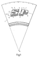
- the letters SP shown in Fig. 1 are delineated, from the basic tyre sidewall 1 by shaded areas 2 to 5.
- the shaded areas 2-5 are positioned to give the visual appearence that the letters themselves are raised above the tyre sidewall surface by a substantial distance.
- the shaded areas cover the area that would be in shadow if the letters were raised from the sidewall, illuminated perpendicularly to their own surface and then viewed from a side angle or perspective viewpoint. This shadow area is referred to herein as the apparent depth zone.
- the shaded areas each comprise a closely spaced set of parallel grooves 6 which are formed in the tyre sidewall as shown in Fig. 2.
- Each groove 6 has a triangular cross-section, a depth D1 of only 0.5 mm and a width D2 at the tread surface of 1.5 mm.
- the grooves are very shallow compared with the normal groove depth for standard markings.
- An important feature is the direction of the grooves 6 which is the radial direction of the tyre.
- Fig. 1 shows a sector of a tyre and this has a central axis at the point A.
- Each letter S and P then has its grooves 6 lying in the radial direction.
- the grooves should be within 10 degrees of the radial direction.
- the groove length L is substantially equal to or less than the width X of the line forming the letters.
- This shading means gives letters or numbers which are particularly clear and distinctive to the human eye but secondary means of delineation may additionally be used.
- the secondary means comprises a 0.8 mm high and 0.8 mm wide rib of sidewall material 7 around the edge of each letter. This shallow rib above does not make the letters distinct but when added to the unexpectedly clear picture by the radial grooves give an enhanced clarity for the letters or numerals.
- the invention is particularly useful for large sidewall markings such as Trade Marks or Trade Names. It allows very large characters to be used whilst providing the very small area of only very shallow grooves and thus gives clearly marked tyres without incurring sidewall weakening features. It is particularly effective for normal black tyre sidewalls as the narrow grooves provide good reflectivity and contrast. Nevertheless, its use is not limited to only black sidewalls nor indeed is the groove section limited to triangular.
Landscapes
- Engineering & Computer Science (AREA)
- Mechanical Engineering (AREA)
- Tires In General (AREA)
Description
- This invention relates to tyre sidewalls and to a means of improving the legibility of sidewall numbers or letters.
- Tyre sidewalls are subjected to constant flexure and sidewall materials are specially designed to withstand this without cracking and consequent failure. Any pattern or shape moulded into the surface inevitably provides sources of potential cracks and so efforts have been made to provide increased clarity of sidewall markings by specially shaped grooves of shallow depth.
- A typical system corresponding to the preamble of claim 1 is shown in GB-A-2010755 where special cross sections for the grooves are disclosed to improve the contrast available for markings. Such a system is effective but has limitations as much grooving is often required which provides very many potentiazl crack initiation points although they are of course very shallow.
- The object of this invention is to provide the legibility of sidewall letters or numbers whilst reducing the amount of grooving and thus to reduce the potential failure sites on the sidewall.
- According to the present invention a tyre sidewall is provided having a sidewall with at least one letter or number presented thereon the letter or number is delineated by means of a series of closely-spaced, parallel, shallow grooves formed in the sidewall surface which grooves extend in a substantially radial direction of the tyre sidewall and all said grooves lie outside the said letter or number which is itself not grooved.
- By grooves is meant grooves formed into the sidewall or ribs formed to provide grooves therebetween.
- The grooves may be provided all around said letter or number but more preferably the grooves extend only throughout an apparent depth zone of the letter or number.
- By apparent depth zone is meant the area which appears beneath it when the letter or number is lifted substantially from the sidewall surface and the sidewall is viewed at an angle. Said zone is similar to the shadow zone of the letter or numeral if lit from a point directly above the letter.
- Preferably, the apparent depth zone is substantially equal to the width of the line forming the letter or numeral to provide the smallest possible grooves area whilst giving effective delineation of the letter.
- The letter or number may also be delineated by a single raised rib having a height from the sidewall of not more than 1 mm and a width of not more than 3.0 mm.
- All the grooves are preferably less than 1 mm in depth and preferably between 0.8 and 0.5 mm in depth. The grooves may be of various cross sectional shapes but a preferred cross section is a triangular section with an apex of said triangle at the deepest point of the groove.
- The present invention will be apparent from the following description, by way of example only, of one embodiment in conjunction with the attached diagrammatic drawings in which:
- Fig. 1 shows a side view of a sector of a tyre sidewall with the letters SP thereon.
- Fig. 2 is a cross section of part of one of the letters on the sidewall of Fig. 1.
- The letters SP shown in Fig. 1 are delineated, from the basic tyre sidewall 1 by
shaded areas 2 to 5. The shaded areas 2-5 are positioned to give the visual appearence that the letters themselves are raised above the tyre sidewall surface by a substantial distance. In fact the shaded areas cover the area that would be in shadow if the letters were raised from the sidewall, illuminated perpendicularly to their own surface and then viewed from a side angle or perspective viewpoint. This shadow area is referred to herein as the apparent depth zone. - The shaded areas each comprise a closely spaced set of
parallel grooves 6 which are formed in the tyre sidewall as shown in Fig. 2. Eachgroove 6 has a triangular cross-section, a depth D1 of only 0.5 mm and a width D2 at the tread surface of 1.5 mm. Thus the grooves are very shallow compared with the normal groove depth for standard markings. An important feature is the direction of thegrooves 6 which is the radial direction of the tyre. Fig. 1 shows a sector of a tyre and this has a central axis at the point A. Each letter S and P then has itsgrooves 6 lying in the radial direction. For a satisfactory appearance and clarity of letters or numerals the inventors have found the grooves should be within 10 degrees of the radial direction. In addition the groove length L is substantially equal to or less than the width X of the line forming the letters. - This shading means gives letters or numbers which are particularly clear and distinctive to the human eye but secondary means of delineation may additionally be used. The secondary means comprises a 0.8 mm high and 0.8 mm wide rib of
sidewall material 7 around the edge of each letter. This shallow rib above does not make the letters distinct but when added to the unexpectedly clear picture by the radial grooves give an enhanced clarity for the letters or numerals. - The invention is particularly useful for large sidewall markings such as Trade Marks or Trade Names. It allows very large characters to be used whilst providing the very small area of only very shallow grooves and thus gives clearly marked tyres without incurring sidewall weakening features. It is particularly effective for normal black tyre sidewalls as the narrow grooves provide good reflectivity and contrast. Nevertheless, its use is not limited to only black sidewalls nor indeed is the groove section limited to triangular.
Claims (7)
Applications Claiming Priority (2)
| Application Number | Priority Date | Filing Date | Title |
|---|---|---|---|
| GB868617409A GB8617409D0 (en) | 1986-07-16 | 1986-07-16 | Tyre sidewalls |
| GB8617409 | 1986-07-16 |
Publications (3)
| Publication Number | Publication Date |
|---|---|
| EP0253557A2 EP0253557A2 (en) | 1988-01-20 |
| EP0253557A3 EP0253557A3 (en) | 1988-07-27 |
| EP0253557B1 true EP0253557B1 (en) | 1991-01-23 |
Family
ID=10601182
Family Applications (1)
| Application Number | Title | Priority Date | Filing Date |
|---|---|---|---|
| EP87306012A Expired - Lifetime EP0253557B1 (en) | 1986-07-16 | 1987-07-08 | Tyre sidewalls |
Country Status (7)
| Country | Link |
|---|---|
| EP (1) | EP0253557B1 (en) |
| JP (1) | JPS6374703A (en) |
| AU (1) | AU7523387A (en) |
| DE (1) | DE3767592D1 (en) |
| ES (1) | ES2019943B3 (en) |
| GB (1) | GB8617409D0 (en) |
| ZA (1) | ZA874692B (en) |
Families Citing this family (14)
| Publication number | Priority date | Publication date | Assignee | Title |
|---|---|---|---|---|
| AT397373B (en) * | 1990-05-14 | 1994-03-25 | Semperit Ag | VEHICLE TIRES |
| JP3072921B2 (en) * | 1991-07-04 | 2000-08-07 | 住友ゴム工業株式会社 | Pneumatic tire |
| CA2180770A1 (en) * | 1996-03-11 | 1997-09-12 | Bill Joe Ratliff, Jr. | Tire sidewall mosaic design patterns |
| JP2006341830A (en) * | 2005-06-10 | 2006-12-21 | Toyo Tire & Rubber Co Ltd | Pneumatic tire |
| JP5160345B2 (en) | 2008-08-26 | 2013-03-13 | 東洋ゴム工業株式会社 | Pneumatic tire |
| JP5708043B2 (en) * | 2011-03-03 | 2015-04-30 | 横浜ゴム株式会社 | Pneumatic tire |
| JP5391249B2 (en) * | 2011-09-15 | 2014-01-15 | 住友ゴム工業株式会社 | Pneumatic tire |
| FR2995254B1 (en) * | 2012-09-12 | 2015-07-17 | Michelin & Cie | PNEUMATIC COMPRISING A HIGH-CONTRAST PATTERN COMPRISING A PLURALITY OF CAVITIES |
| JP6209870B2 (en) * | 2013-06-14 | 2017-10-11 | 横浜ゴム株式会社 | Pneumatic tire |
| FR3007325B1 (en) * | 2013-06-21 | 2016-02-12 | Michelin & Cie | PNEUMATIC COMPRISING A HIGH CONTRAST MARKING |
| DE102015205007A1 (en) * | 2015-03-19 | 2016-09-22 | Continental Reifen Deutschland Gmbh | Pneumatic vehicle tire and vulcanization mold for vulcanization of a pneumatic vehicle tire |
| DE102019207943A1 (en) * | 2019-05-29 | 2020-12-03 | Continental Reifen Deutschland Gmbh | Pneumatic vehicle tires having a hatched area |
| JP7494648B2 (en) * | 2020-08-24 | 2024-06-04 | 住友ゴム工業株式会社 | tire |
| JP2022166645A (en) * | 2021-04-21 | 2022-11-02 | Toyo Tire株式会社 | pneumatic tire |
Family Cites Families (5)
| Publication number | Priority date | Publication date | Assignee | Title |
|---|---|---|---|---|
| DE2640343A1 (en) * | 1976-09-08 | 1978-03-09 | Rudolf Bach | Vehicle tyre identification system - has ribbed panels on which may be engraved vehicle identification data |
| US4198774A (en) * | 1977-11-18 | 1980-04-22 | The Goodyear Tire & Rubber Company | Indicia for rubber articles |
| GB2010755B (en) * | 1977-12-23 | 1982-06-16 | Dunlop Ltd | Shallow relief patterns on tyre sidewalls |
| JPS5531962A (en) * | 1978-08-29 | 1980-03-06 | Nec Corp | Water depth measuring unit of laser |
| US4444713A (en) * | 1982-08-09 | 1984-04-24 | The Goodyear Tire & Rubber Company | Decorative ornamentation for a rubber article and method of making same |
-
1986
- 1986-07-16 GB GB868617409A patent/GB8617409D0/en active Pending
-
1987
- 1987-06-29 ZA ZA874692A patent/ZA874692B/en unknown
- 1987-07-03 AU AU75233/87A patent/AU7523387A/en not_active Abandoned
- 1987-07-07 JP JP62169956A patent/JPS6374703A/en active Pending
- 1987-07-08 ES ES87306012T patent/ES2019943B3/en not_active Expired - Lifetime
- 1987-07-08 DE DE8787306012T patent/DE3767592D1/en not_active Expired - Lifetime
- 1987-07-08 EP EP87306012A patent/EP0253557B1/en not_active Expired - Lifetime
Also Published As
| Publication number | Publication date |
|---|---|
| AU7523387A (en) | 1988-01-21 |
| GB8617409D0 (en) | 1986-08-20 |
| JPS6374703A (en) | 1988-04-05 |
| EP0253557A3 (en) | 1988-07-27 |
| ES2019943B3 (en) | 1991-07-16 |
| ZA874692B (en) | 1988-01-04 |
| EP0253557A2 (en) | 1988-01-20 |
| DE3767592D1 (en) | 1991-02-28 |
Similar Documents
| Publication | Publication Date | Title |
|---|---|---|
| EP0522781B1 (en) | Tyre | |
| EP0253557A2 (en) | Tyre sidewalls | |
| EP0751014A2 (en) | Design patterns for a tire sidewall | |
| EP1310384B1 (en) | Vehicle tire | |
| EP0950548B1 (en) | High impact logo structure for tire sidewall and its manufacturing method | |
| EP0216566B1 (en) | Pneumatic radial tyre | |
| JPH0986106A (en) | Pneumatic tire | |
| KR890011714A (en) | Pneumatic tire | |
| MXPA96002370A (en) | Design patterns for a side wall della | |
| USD394030S (en) | Tire tread | |
| CA2024231A1 (en) | Tire treads | |
| CN101108575B (en) | Vehicle tire | |
| JPH066967Y2 (en) | tire | |
| HUT41680A (en) | Vehicle tyre particularly radial one for trucks | |
| JP4229320B2 (en) | Pneumatic tire | |
| JPH09226328A (en) | Pneumatic tire with a mark consisting of multiple ridges | |
| US4939994A (en) | Engraved printing rolls | |
| KR910000334A (en) | Tire shaping method and mold for implementing the method | |
| DE3271385D1 (en) | Tread profile for vehicle tyres | |
| EP0357462A3 (en) | Pneumatic tires | |
| EP3511180B1 (en) | Tyre | |
| EP0778163B1 (en) | Pneumatic tyre | |
| KR200198256Y1 (en) | Bias tire | |
| CA1301540C (en) | Engraved printing rolls and process of making | |
| EP3533634A1 (en) | Tyre |
Legal Events
| Date | Code | Title | Description |
|---|---|---|---|
| PUAI | Public reference made under article 153(3) epc to a published international application that has entered the european phase |
Free format text: ORIGINAL CODE: 0009012 |
|
| AK | Designated contracting states |
Kind code of ref document: A2 Designated state(s): DE ES FR GB IT |
|
| PUAL | Search report despatched |
Free format text: ORIGINAL CODE: 0009013 |
|
| AK | Designated contracting states |
Kind code of ref document: A3 Designated state(s): DE ES FR GB IT |
|
| 17P | Request for examination filed |
Effective date: 19890125 |
|
| 17Q | First examination report despatched |
Effective date: 19900629 |
|
| GRAA | (expected) grant |
Free format text: ORIGINAL CODE: 0009210 |
|
| AK | Designated contracting states |
Kind code of ref document: B1 Designated state(s): DE ES FR GB IT |
|
| ITF | It: translation for a ep patent filed | ||
| REF | Corresponds to: |
Ref document number: 3767592 Country of ref document: DE Date of ref document: 19910228 |
|
| ET | Fr: translation filed | ||
| PLBE | No opposition filed within time limit |
Free format text: ORIGINAL CODE: 0009261 |
|
| STAA | Information on the status of an ep patent application or granted ep patent |
Free format text: STATUS: NO OPPOSITION FILED WITHIN TIME LIMIT |
|
| 26N | No opposition filed | ||
| PGFP | Annual fee paid to national office [announced via postgrant information from national office to epo] |
Ref country code: GB Payment date: 20010605 Year of fee payment: 15 |
|
| PGFP | Annual fee paid to national office [announced via postgrant information from national office to epo] |
Ref country code: ES Payment date: 20010716 Year of fee payment: 15 |
|
| PGFP | Annual fee paid to national office [announced via postgrant information from national office to epo] |
Ref country code: FR Payment date: 20010731 Year of fee payment: 15 |
|
| PGFP | Annual fee paid to national office [announced via postgrant information from national office to epo] |
Ref country code: DE Payment date: 20010814 Year of fee payment: 15 |
|
| REG | Reference to a national code |
Ref country code: GB Ref legal event code: IF02 |
|
| PG25 | Lapsed in a contracting state [announced via postgrant information from national office to epo] |
Ref country code: GB Free format text: LAPSE BECAUSE OF NON-PAYMENT OF DUE FEES Effective date: 20020708 |
|
| PG25 | Lapsed in a contracting state [announced via postgrant information from national office to epo] |
Ref country code: ES Free format text: LAPSE BECAUSE OF NON-PAYMENT OF DUE FEES Effective date: 20020709 |
|
| PG25 | Lapsed in a contracting state [announced via postgrant information from national office to epo] |
Ref country code: DE Free format text: LAPSE BECAUSE OF NON-PAYMENT OF DUE FEES Effective date: 20030201 |
|
| GBPC | Gb: european patent ceased through non-payment of renewal fee |
Effective date: 20020708 |
|
| PG25 | Lapsed in a contracting state [announced via postgrant information from national office to epo] |
Ref country code: FR Free format text: LAPSE BECAUSE OF NON-PAYMENT OF DUE FEES Effective date: 20030331 |
|
| REG | Reference to a national code |
Ref country code: FR Ref legal event code: ST |
|
| REG | Reference to a national code |
Ref country code: ES Ref legal event code: FD2A Effective date: 20030811 |
|
| PG25 | Lapsed in a contracting state [announced via postgrant information from national office to epo] |
Ref country code: IT Free format text: LAPSE BECAUSE OF NON-PAYMENT OF DUE FEES Effective date: 20050708 |