EP0253324A2 - Method and apparatus for reducing sulphur dioxide content in flue gases - Google Patents
Method and apparatus for reducing sulphur dioxide content in flue gases Download PDFInfo
- Publication number
- EP0253324A2 EP0253324A2 EP87109975A EP87109975A EP0253324A2 EP 0253324 A2 EP0253324 A2 EP 0253324A2 EP 87109975 A EP87109975 A EP 87109975A EP 87109975 A EP87109975 A EP 87109975A EP 0253324 A2 EP0253324 A2 EP 0253324A2
- Authority
- EP
- European Patent Office
- Prior art keywords
- zone
- particles
- air
- combustion
- lime
- Prior art date
- Legal status (The legal status is an assumption and is not a legal conclusion. Google has not performed a legal analysis and makes no representation as to the accuracy of the status listed.)
- Granted
Links
Images
Classifications
-
- F—MECHANICAL ENGINEERING; LIGHTING; HEATING; WEAPONS; BLASTING
- F23—COMBUSTION APPARATUS; COMBUSTION PROCESSES
- F23J—REMOVAL OR TREATMENT OF COMBUSTION PRODUCTS OR COMBUSTION RESIDUES; FLUES
- F23J3/00—Removing solid residues from passages or chambers beyond the fire, e.g. from flues by soot blowers
-
- B—PERFORMING OPERATIONS; TRANSPORTING
- B01—PHYSICAL OR CHEMICAL PROCESSES OR APPARATUS IN GENERAL
- B01D—SEPARATION
- B01D53/00—Separation of gases or vapours; Recovering vapours of volatile solvents from gases; Chemical or biological purification of waste gases, e.g. engine exhaust gases, smoke, fumes, flue gases, aerosols
- B01D53/34—Chemical or biological purification of waste gases
- B01D53/46—Removing components of defined structure
- B01D53/48—Sulfur compounds
- B01D53/50—Sulfur oxides
- B01D53/508—Sulfur oxides by treating the gases with solids
-
- F—MECHANICAL ENGINEERING; LIGHTING; HEATING; WEAPONS; BLASTING
- F23—COMBUSTION APPARATUS; COMBUSTION PROCESSES
- F23J—REMOVAL OR TREATMENT OF COMBUSTION PRODUCTS OR COMBUSTION RESIDUES; FLUES
- F23J7/00—Arrangement of devices for supplying chemicals to fire
Definitions
- the present invention relates generally to the removal of pollutants from flue gases and more particularly to a method and apparatus for removing sulfur dioxide from flue gases exhausted from boilers fired with sulfur-containing fuel.
- Sulfur-containing fuels such as coal, coke oven gas or fuel oil
- the fuel is combusted with air, in excess of the stoichiometric amount required for combustion, at a series of burners in an enclosed combustion chamber to produce combustion reaction products consisting primarily of hot gases but also containing some particulates, such as fly ash.
- Heat is extracted from the hot gases, in a conventional manner, to heat water and produce steam.
- the hot gases are flowed in a downstream direction and eventually are exhausted through a stack. Residual heat remaining in the hot gases, after completion of the steam producing function, may be used to preheat combustion air.
- the temperature decreases in a downstream direction after the last burner. Moreover, at any location along the downstream path there can be a spread of different processing temperatures across the lateral dimensions of the combustion zone. However, at any such location, there is also an average temperature, and the average temperature is the temperature reference used herein, unless otherwise indicated.
- the hot gases from the combustion reaction include undesirable pollutants, both solid and gaseous.
- Solid particulate pollutants are usually removed in an electrostatic precipitator or a bag house or both.
- Gaseous pollutants have included oxides of nitrogen (NO x ) and sulfur dioxide (SO2).
- NO x oxides of nitrogen
- SO2 sulfur dioxide
- a high sulfur dioxide content in the gases is especially undesirable because, if allowed to escape into the atmosphere, it can be a source of acid rain as well as other undesirable effects.
- a sorbent is a compound which reacts with the sulfur dioxide to produce a relatively innocuous, solid compound which can be removed from the flue gases with conventional particulate removal apparatus.
- dry injection sorbent materials previously employed to remove sulfur dioxide from flue gases resulting from the combustion of coal include the carbonates or hydroxides of magnesium and calcium. Limestone (calcium carbonate) particles have been employed as a dry sorbent injection material in coal fired boilers.
- the sulfur dioxide in the flue gases is converted to calcium sulfate, an innocuous solid compound which can be employed as a construction material or which may be buried in a land fill without concern for adverse effects on the environment.
- the particles of limestone or calcium carbonate (CaCO3) are calcined into lime (CaO) by the heat from the combustion reaction, and the lime reacts with the sulfur dioxide, in the presence of oxygen (from the excess air in the combustion chamber) to produce calcium sulfate (CaSO4).
- Such a burner design generally includes a nozzle through which the fuel is injected into the combustion chamber together with so-called primary air. Also injected into the combustion chamber, at locations closely adjacen t the fuel nozzle, is secondary air which, together with the primary air, accounts for about 0.7-1.0 times the stoichiometric amount of oxygen required for complete combustion. In addition to the primary and secondary air, tertiary air is also injected into the combustion chamber from locations either closely surrounding, or remotely spaced in a downstream direction from, the inlets for the secondary air.
- Employing a burner arrangement of the type described in the preceding paragraph reduces or eliminates peak flame temperatures, the presence of which accounts for oxides of nitrogen produced from nitrogen in the combustion air.
- the aforementioned burner arrangement also reduces the oxygen concentration in the pyrolysis or chemical reaction zone of the flame, which controls the formation of oxides of nitrogen from the nitrogen contained in the fuel.
- Premixing the limestone particles with the combustion air causes erosion and pluggage problems in the transporting conduits for the combustion air and reduces substantially the accuracy with which the particles can be divided among the sub-streams to the individual air outlets, a multiplicity of which are usually employed. These problems arise from the high velocity at which the combustion air flows through the transporting conduits, e.g. 2,500-5,000 ft/min. (762-1524 m/min.) and the fact that the limestone particles are carried in dilute phase transport.
- the velocity of the transporting combustion air is reduced to decrease the erosion and pluggage problems, the volume of the transporting air has to be increased in order to carry the limestone in ditute phase transport at the slower speeds; and this could result in more combustion air at a given outlet, or series of outlets, than is desired from the standpoint of combustion or other considerations.
- lowering the velocity at which the combustion air is introduced into the combustion chamber reduced the turbulence and mixing action due to the combustion air, and such a reduction is undesirable.
- a minimum velocity is necessary in order for the combustion air to properly distribute within the combustion chamber the limestone particles carried by the combustion air.
- the invention as claimed is intended to overcome or to reduce the above problem.
- Sulfur dioxide in the flue gases is removed by employing a combinat ion of limestone particle injection and a low NO x burner system employing overfire air, with certain parameters controlled in a particular manner in order to obtain the desired results.
- Fuel such as pulverized coal, and primary and secondary air are introduced into a first combustion zone.
- Tertiary air is introduced into a second combustion zone located downstream, typically above, and relatively remotely spaced from the first combustion zone. When introduced at such a location, the tertiary air is referred to as overfire air.
- combustion reaction gases or flue gases flow downstream from the first combustion zone through the second combustion zone and further downstream thereform, they lose heat relatively rapidly in the process of heating water to produce steam.
- the air introduced into the first combustion zone is hereafter referred to as the major portion of the combustion air, and the tertiary air, introduced into the second combustion zone as overfire air, is hereinafter referred to as the second portion of combustion air.
- Limestone particles or the like are introduced into the second portion of combustion air which has a velocity sufficient to aspirate the limestone particles into and distribute them throughout the gases flowing downstream through the second combustion zone. There is no premixing of the limestone particles and the second portion of combustion air before they enter the second combustion zone.
- the second portion of combustion air is provided with a velocity sufficient to buffer peak temperatures in the flames from the first combustion zone and spread out and provide a relatively uniform flame front in the second combustion zone.
- the aforementioned average processing temperature range is high enough (above 1600°F or 871°C) and prevails long enough (longer than 0.5 sec.) to react the lime produced downstream of the first combustion zone with the desired amount of SO2 gas during the time in which the lime and the SO2 gas are subjected to the average processing temperature range.
- the combustion air may be transported at high speeds undicated by erosion or plugging considerations, and the volume of the combustion air is undicated by limestone transporting considerations.
- limestone particles are conveyed in dense phase transport, they may be accurately divided into respective substreams, to whatever extent desired, for a multiplicity of outlets at the second zone.
- the SO2 content of flue gases exhausted from the stack of a boiler operated in accordance with the present invention is 400-500 parts per million (ppm).
- Boiler 10 is an embodiment of a boiler for combusting fuel to heat water to generate steam.
- Boiler 10 comprises a combustion chamber indicated generally at 11 having first and second combustion zones 12, 13 respectively.
- Combustion chamber 11 is defined by heat exchange walls 24 on the opposite side of which water is flowed, in a conventional manner, for absorbing heat from combustion chamber 11 generated therein by a combustion reaction.
- heat exchange walls 24 can be a ring of vertical tubes through which water is flowed.
- first combustion zone 12 Communicating with first combustion zone 12 are a plurality of vertically spaced nozzle 16, 17, 18 for introducing fuel and primary air into first combustion zone 12.
- a line 15 communicates with each of nozzles 16, 17, 18 through respective branch lines 116, 117 and 118 for introducing fuel and primary air into the nozzles.
- Ports 21-23 communicate with a pressurized wind box 19 in turn communicating with the upstream end of a conduit 20 for introducing preheated air into wind box 19.
- Pipe 28 Disposed substantially coaxially within tubular port 27 is a pipe 28 terminating at an open downstream end 29.
- Pipe 28 is employed to inject limestone particles into the stream of tertiary air as the stream enters second combustion zone 13. There is no premixing of the limestone particles in pipe 28 with tertiary air before the particles enter second combustion zone 13 at pipe end 29.
- a pipe 28 may be associated with four of the six ports. Introducing the limestone particles through four peripherally spaced ports 27 assists in the widespread horizontal distribution of limestone particles in second zone 13 compared to introduction through only one or two ports.
- the limestone particles are stored in a hopper 30 which feeds into a conduit 31 extending downwardly from hopper 30 to line 28. Communicating with pipe 28 is a conduit 32 through which flows a transport gas for transporting the limestone particles from hopper 30 through pipe 28.
- Limestone particles are the preferred material for producing lime particles by calcination in the combustion chamber.
- Other finely divided materials which form lime particles upon exposure to the heat in the second combustion zone, may be employed. These include calcium hydroxide, Ca(OH)2, and dolomite, CaMg(CO3)2, which calcines to produce a reaction product which is about 80 wt.% lime and 20 wt.% MgO.
- the MgO does not usually participate in SO2 removal to any substantial degree in the method of the present invention.
- Combustion reaction gases are generated in combustion chamber 11 and flow upwardly (downstream) past primary and secondary superheaters 35, 36 respectively for superheating the steam generated at boiler 10.
- the combustion reaction gases, or flue gases then flow downstream through a conduit 37 which communicates with conventional apparatus (not shown) for removing particulates from the flue gas and with conventional heat exchange apparatus (not shown) for preheating the air which is eventually flowed through conduit 20 and line 15.
- conventional apparatus not shown
- heat exchange apparatus not shown
- a mixture of primary air and a sulfur-containing fuel are flowed through line 15 into nozzles 16-18.
- the sulfur- containing fuel may be coal, fuel oil, or coke oven gas, for example.
- the total amount of primary, secondary and tertiary air is in excess of the stochiometric amount required to combust the fuel introduced through nozzles 16-18.
- a major portion of the combustion air is introduced into first combustion zone 12, through nozzles 16-18 and ports 21-23, together with or closely adjacent the fuel to at least partially combust the fuel.
- a second portion of air, constituting the remainder of the air or tertiary air, is introduced as overfire air into the combustion chamber at second zone 13 through port 27.
- first zone 12 At least some combustion occurs in first zone 12, and the contents of the first zone including the combustion reaction products as well as uncombusted fuel, if any, flow downstream from first zone 12 through second zone 13.
- Flames generated in first combustion zone 12 extend downstream towards second combustion zone 13 as a flame front which is not uniform, containing peak flame temperatures which are higher than other temperatures across the flame front.
- the second portion of air is introduced at a location (port 27) and with a velocity (e.g 5000 ft/min.) (1,524 m/min.) for accomplishing these purposes.
- the resulting uniform flame front, in which peak flame temperatures have been buffered, is indicated at 42 in Fig. 2.
- the minimum velocity of the second portion of air should be about 2,500 ft/min. (762 m/min.) in order to produce these results.
- the gases moving through second combustion zone 13 include sulfur dioxide.
- f inely divided limestone particles are introduced into second zone 13 together with and under the urging of the second portion of air.
- a stream of limestone particles 33 enters second combustion zone 13 at the downstream open end 29 of pipe 28.
- the second portion of air entering second combustion zone 13 at port 27 distributes the limestone particles throughout the gases flowing downstream through the second zone.
- the limestone particles entering the second zone are flash calcined downstream of first zone 12 to produce particles of lime which reacts with at least part of any sulfur dioxide present, in the presence of oxygen from that part of the air which is in excess of that stochiometrically required to react with the fuel, to produce calcium sulfate.
- second combustion zone 13 The contents of second combustion zone 13 are flowed downstream away from the first and second combustion zones 12, 13.
- the average temperature in first combustion zone 12 exceeds the sintering temperature of the limestone and lime particles (1316°C or 2400°F).
- the location and velocity of the second portion of air is such as to provide an average processing temperature range, downstream of first combustion zone 12 which is below the sintering temperature for the limestone and lime particles as well as being below the temperature at which calcium sulfate decomposes into lime and gaseous oxides of sulfur (1349°C or 2460°F).
- Sintering is undesirable because it decreases the surface area of the resulting lime particles which reduces the reactivity thereof. Therefore, the temperature in second zone 13 and downstream from there is high enough for flash calcination of the finely divided limestone particles but low enough to avoid sintering of the resulting lime particles.
- the average processing temperature range is about 1600°-2400°F (871°-1316°C). This is high enough and prevails long enough for the lime, produced downstream of first combustion zone 12, to react with a desired amount of sulfur dioxide gas during the time in which the lime and the sulfur dioxide gas are subjected to that temperature range.
- the lime and sulfur dioxide gas are subjected to the average processing temperature range for more than 0.5 seconds, preferably at least 1.5 seconds.
- the limestone particles are flash calcined to particles of lime in less than 0.1 second, so that the rest of the time during which the particles are subjected to the temperature range 1600°-2400°F (871°-1316°C) is time in which a reaction with sulfur dioxide can occur.
- the length of time in which sulfur dioxide and lime are subjected to the desired average processing temperature range of 1600°-2400°F (871°-1316°C) can be increased by reducing the amount of excess air (e.g. from 3% to 1.5%), by reducing the rate at which steam is generated (i.e. the rate at which heat is exchanged through the walls 24 of combustion chamber 12 or superheaters 35 and 36), by reducing the velocity of the gases flowing downstream from the combusiton chamber, etc.
- the limestone particles introduced into second combustion zone 13 are transported up to the combustion zone by the transport gas from conduit 32. Before entering second combustion zone 13, the limestone particles have imparted thereto by the transport gas a velocity sufficient to carry the limestone particles up to the second zone but intentionally insufficient to distribute the limestone particles across the second zone. This minimizes the amount of air introduced into pipe 28 and thereby the amount of extraneous air introduced into the combustion chamber, an advantage which will be discussed more fully below.
- Distribution of the limestone particles across the second zone is accomplished by the high velocity air introduced at port 27.
- This air has a velocity which not only buffers the flames from first combustion zone 12 but also aspirates the lim estone particles into, and distributes them across, the second zone.
- distribution is enhanced by the turbulence 43 caused at least in part when the high velocity second portion of air is directed laterally across the second zone.
- the limestone particles are carried up to second zone 13, i.e. up to open end 29 in pipe 28, under dense phase transport. This is accomplished by mixing the limestone particles entering pipe 28 from conduit 31 with transporting air in an amount which imparts dense phase transport.
- the minimum solids to gas ratio for dense phase transport is about 20 to 1, and a typical ratio employed in accordance with the present invention is about 90 to 1.
- the minimum velocity required to provide a dense phase transport of limestone particles having a maximum particle size of minus 100 mesh on a wet screen basis is about 300 ft/min. (91 m/min.).
- a typical gas pressure in conduit 32 is 15-30 psig (103.5-207 kPa).
- wet screen basis reflects the fact that the limestone particles have been subjected to water before screening, and this enables the screening out of particles which have undergone agglomeration as a result of being subjected to water.
- the velocity with which the limestone particles are conveyed thorugh pipe 28 to open pipe end 29 can vary over a wide range, e.g. 300 ft/min (91 m/min.) to 10,000 ft/min. (3,048 m/min.), with little effect on the limestone particle distribution in zone 13. This is because the tertiary air introduced at port 27, typically at a velocity of 5,000 ft/min (1524 m/min.), performs the totality of the limestone particles distribution function in zone 13, and this is so even when the velocity in pipe 28 is 10,000 ft/min. (3,048 m/min.). The velocity of the particles in pipe 28 plays virtually no role in the distribution of limestone particles in zone 13.
- the relative volume of air moving through pipe 28 is insubstantial compared to the volume of tertiary air entering zone 13 at port 27, no matter the velocity in pipe 28.
- the cross-sectional area of elements 25-27, through which the tertiary air is transported is very much greater than that of pipe 28.
- the total cross-sectional area of the latter is less than 2% of the total cross-sectional area of the former.
- the second portion of combustion air may be introduced into second zone 13 at whatever high velocity is necessary to provide the desired buffering, turbulence and particle mixing and distributing effects.
- the velocity and volume of combustion air introduced at ports 27 is undicated by limestone transporting considerations.
- the limestone particles move through conduit 28 in dense phase transport at a relatively very slow speed, e.g. about 360 ft/min. (110 m/min.), for example. At such low speeds, there is relatively no erosion in pipe 28, and the likelihood of plugging in pipe 28 is reduced substantially. The likelihood of plugging increases with the speed of particle travel.
- the velocity of the second air portion is 2500-5,000 ft/min. (762-1524 m/min), so that the speed of particle travel in conduit 25 would be much faster than in pipe 28, thereby substantially increasing the likelihood of pluggage if there were premixing.
- the stream of limestone particles may be very accurately divided into substreams merely by controlling the cross-sectional area of the substream conduits.
- a stream in dense phase transport may be divided into two equal substreams by providing the two substream conduits with equal cross-sectional areas. This feature is not available with dilute phase transport.
- the desired amount of surface area is provided by supplying limestone particles smaller than 100 mesh (less than 150 microns) on a wet screen basis.
- the limestone particles have a size, in the range between about 5 microns and minus 100 mesh, on a wet screen basis, sufficient to provide the reaction required to eliminate the sulfur dioxide gas to the extent required.
- the limestone particles comprise about 70% smaller than 200 mesh (less than 75 microns), on a wet screen basis.
- reactivity may be increased by reducing the particle size, all other factors being constant. Reducing the particle size increases the surface area of the lime and results in a better distribution of the particles, but it also increases the expense. Typically, one employs the coarsest particle size, in the range of about 5 microns to minus 100 mesh, that will give the desired amount of SO2 removal.
- the amount of limestone injected depends upon the amount of sulfur dioxide which has to be converted to calcium sulfate and this depends upon the initial and final desired sulfur dioxide contents of the flue gases. Generally speaking, an increase in the calcium to sulfur ratio increases the sulfur dioxide removal efficiency, although not on a linear basis.
- SO2 removal will continue because of the lime content of the deposits on the inside surface of the boiler walls. More particularly, SO2 is absorbed into the deposits and reacts with the lime therein to form calcium sulfate (CaSO4) there. This can continue for up to 3 days, with decreasing SO2 removal, starting at about 5-7% SO2 removal at the beginning of the shut down period for limestone injection. Therefore, should there be a need to shut down the limestone injecting apparatus, e.g. for maintenance, servicing or the like, SO2 removal will continue for awhile, at least to some extent.
- soot blowing during the period when limestone injection is shut down, to retain the deposits or parts thereof, and their SO2-absorbing function, during that period. For example, after SO2 absorption into a deposit has occurred for awhile, there will be a buildup of calcium sulfate in an outer layer of the deposit. Soot blowing of reduced longevity, sufficient to remove only this outer layer and expose a fresh outer layer devoid of calcium sulfate would then be desirable. It would be undesirable to remove the entire deposit in one soot blowing operation. When the SO2-absorbing properties of the innermost layer of the deposits has been depleted, removal of the deposits can be completed, with soot blowing.
- Acids can form as a result of the combustion reaction. These acids include primarily sulfuric acid but also hydrochloric and nitric acids. Acids are undesirable because, if they precipitate out of the flue gases somewhere in the system, they can severely corrode the system's components, among other things. It has been conventional in the past to operate the boiler system in such a manner as to produce a flue gas exhaust temperature above the dew point of the acids, e.g. a stack exhaust temperature in the range 300°-350°F (148°-177°C). This prevents the acids from precipitating out of the flue gases anywhere in the system, but it is accomplished at the expense of heat utilization elsewhere, e.g. for generating steam.
- Limestone injection forms lime which neutralizes the acids. Therefore, acid precipitation from the flue gases is not a problem, and one need not maintain the fl ue gases at an exhaust temperature above the dew point of the acids. As a result, the system can be operated with a lower stack exhaust temperature, e.g. 110°-250°F (43°-121°C), and more heat can be extracted from the flue gases to generate steam.
- a lower stack exhaust temperature e.g. 110°-250°F (43°-121°C)
Landscapes
- Engineering & Computer Science (AREA)
- Chemical & Material Sciences (AREA)
- Mechanical Engineering (AREA)
- General Engineering & Computer Science (AREA)
- Health & Medical Sciences (AREA)
- Environmental & Geological Engineering (AREA)
- Biomedical Technology (AREA)
- Analytical Chemistry (AREA)
- General Chemical & Material Sciences (AREA)
- Oil, Petroleum & Natural Gas (AREA)
- Chemical Kinetics & Catalysis (AREA)
- Treating Waste Gases (AREA)
- Fluidized-Bed Combustion And Resonant Combustion (AREA)
- Combustion Of Fluid Fuel (AREA)
Abstract
Description
- The present invention relates generally to the removal of pollutants from flue gases and more particularly to a method and apparatus for removing sulfur dioxide from flue gases exhausted from boilers fired with sulfur-containing fuel.
- Sulfur-containing fuels, such as coal, coke oven gas or fuel oil, are typically used to fire boilers for producing steam to generate electricity and/or for heating or processing purposes. Typically, the fuel is combusted with air, in excess of the stoichiometric amount required for combustion, at a series of burners in an enclosed combustion chamber to produce combustion reaction products consisting primarily of hot gases but also containing some particulates, such as fly ash. Heat is extracted from the hot gases, in a conventional manner, to heat water and produce steam. The hot gases are flowed in a downstream direction and eventually are exhausted through a stack. Residual heat remaining in the hot gases, after completion of the steam producing function, may be used to preheat combustion air.
- In the combustion chamber, the temperature decreases in a downstream direction after the last burner. Moreover, at any location along the downstream path there can be a spread of different processing temperatures across the lateral dimensions of the combustion zone. However, at any such location, there is also an average temperature, and the average temperature is the temperature reference used herein, unless otherwise indicated.
- The hot gases from the combustion reaction include undesirable pollutants, both solid and gaseous. Solid particulate pollutants are usually removed in an electrostatic precipitator or a bag house or both. Gaseous pollutants have included oxides of nitrogen (NO x) and sulfur dioxide (SO₂). Within the last few years, the NO x content of the gases has been reduced by changes in combustion techniques for oil and gas-fired boilers and by changes in burner design for coal-fired boilers.
- A high sulfur dioxide content in the gases is especially undesirable because, if allowed to escape into the atmosphere, it can be a source of acid rain as well as other undesirable effects.
- Attempts have been made to reduce the sulfur dioxide content of the combustion reaction gases (flue gases) by an expedient known as dry sorbent injection. A sorbent is a compound which reacts with the sulfur dioxide to produce a relatively innocuous, solid compound which can be removed from the flue gases with conventional particulate removal apparatus. Examples of dry injection sorbent materials previously employed to remove sulfur dioxide from flue gases resulting from the combustion of coal include the carbonates or hydroxides of magnesium and calcium. Limestone (calcium carbonate) particles have been employed as a dry sorbent injection material in coal fired boilers. In such a system, the sulfur dioxide in the flue gases is converted to calcium sulfate, an innocuous solid compound which can be employed as a construction material or which may be buried in a land fill without concern for adverse effects on the environment. Initially, the particles of limestone or calcium carbonate (CaCO₃) are calcined into lime (CaO) by the heat from the combustion reaction, and the lime reacts with the sulfur dioxide, in the presence of oxygen (from the excess air in the combustion chamber) to produce calcium sulfate (CaSO₄).
- As noted above, oxides of nitrogen in the flue gases have been reduced by employing an improved burner design. Such a burner design generally includes a nozzle through which the fuel is injected into the combustion chamber together with so-called primary air. Also injected into the combustion chamber, at locations closely adjacen t the fuel nozzle, is secondary air which, together with the primary air, accounts for about 0.7-1.0 times the stoichiometric amount of oxygen required for complete combustion. In addition to the primary and secondary air, tertiary air is also injected into the combustion chamber from locations either closely surrounding, or remotely spaced in a downstream direction from, the inlets for the secondary air.
- Employing a burner arrangement of the type described in the preceding paragraph reduces or eliminates peak flame temperatures, the presence of which accounts for oxides of nitrogen produced from nitrogen in the combustion air. The aforementioned burner arrangement also reduces the oxygen concentration in the pyrolysis or chemical reaction zone of the flame, which controls the formation of oxides of nitrogen from the nitrogen contained in the fuel.
- Attempts have been made by others, at least on a test basis, to inject limestone particles in a system employing burners of the type producing a low percentage of oxides of nitrogen, hereinafter referred to as low NO x burners. In these attempts, limestone has been injected into the combustion chamber through the fuel nozzles, through the inlets for introducing the secondary air (located closely adjacent the fuel nozzle), through tertiary air inlets closely surrounding the inlets for the secondary air, and through separate limestone-injecting inlets spaced relatively far downstream from the inlets for the fuel and the combustion air. In the first three instances, the limestone was premixed with the fuel and/or the combustion air entering the combustion chamber at the secondary and tertiary air inlets.
- There are drawbacks to all of the limestone injection techniques described in the preceding paragraph. Injection through the fuel nozzle or through secondary air inlets immediately adjacent the fuel nozzle or through tertiary air inlets closely surrounding the secondary air inlets subjects the limestone particles to relatively high temperatures for relatively long periods of time, and that can cause sintering of the resulting lime particles which reduces their surface area and therefore their ability to react with SO₂, thereby decreasing SO₂ removal. Introducing the limestone particles relatively far downstream from the fuel nozzles and combustion air inlets decreases SO₂ removal because the temperature conditions are too low and/or decrease too rapidly.
- Premixing the limestone particles with the combustion air causes erosion and pluggage problems in the transporting conduits for the combustion air and reduces substantially the accuracy with which the particles can be divided among the sub-streams to the individual air outlets, a multiplicity of which are usually employed. These problems arise from the high velocity at which the combustion air flows through the transporting conduits, e.g. 2,500-5,000 ft/min. (762-1524 m/min.) and the fact that the limestone particles are carried in dilute phase transport.
- If the velocity of the transporting combustion air is reduced to decrease the erosion and pluggage problems, the volume of the transporting air has to be increased in order to carry the limestone in ditute phase transport at the slower speeds; and this could result in more combustion air at a given outlet, or series of outlets, than is desired from the standpoint of combustion or other considerations. Moreover, lowering the velocity at which the combustion air is introduced into the combustion chamber reduced the turbulence and mixing action due to the combustion air, and such a reduction is undesirable. Furthermore, a minimum velocity is necessary in order for the combustion air to properly distribute within the combustion chamber the limestone particles carried by the combustion air.
- The invention as claimed is intended to overcome or to reduce the above problem.
- Sulfur dioxide in the flue gases is removed by employing a combinat ion of limestone particle injection and a low NO x burner system employing overfire air, with certain parameters controlled in a particular manner in order to obtain the desired results.
- Fuel, such as pulverized coal, and primary and secondary air are introduced into a first combustion zone. Tertiary air is introduced into a second combustion zone located downstream, typically above, and relatively remotely spaced from the first combustion zone. When introduced at such a location, the tertiary air is referred to as overfire air.
- As the combustion reaction gases or flue gases flow downstream from the first combustion zone through the second combustion zone and further downstream thereform, they lose heat relatively rapidly in the process of heating water to produce steam.
- The air introduced into the first combustion zone is hereafter referred to as the major portion of the combustion air, and the tertiary air, introduced into the second combustion zone as overfire air, is hereinafter referred to as the second portion of combustion air.
- Limestone particles or the like are introduced into the second portion of combustion air which has a velocity sufficient to aspirate the limestone particles into and distribute them throughout the gases flowing downstream through the second combustion zone. There is no premixing of the limestone particles and the second portion of combustion air before they enter the second combustion zone.
- In the first combustion zone, at least the peak flame temperatures, if not the average flame temperature, are above the temperature at which limestone and lime particles will sinter. Calcination of the particles to lime occurs so rapidly that sintering considerations apply essentially only to the lime particles. Sintering of the lime particles is undesirable as it will lower the reactivity of the lime particles. Accordingly, the second portion of combustion air is provided with a velocity sufficient to buffer peak temperatures in the flames from the first combustion zone and spread out and provide a relatively uniform flame front in the second combustion zone. As a result of the velocity and entry location of the second portion of combustion air, there is an average processing temperature range, downstream of the first combustion zone, which is below the sintering temperature for the lime particles (2400°F or 1316°C), as well as below the temperature at which calcium sulfate decomposes into lime and gaseous oxides of sulfur (2460°F or 1349°C). In addition, there are substantially no peak flame temperatures, downstream of the first combustion zone, which are high enough to have an adverse sintering effect on the lime particles.
- The aforementioned average processing temperature range is high enough (above 1600°F or 871°C) and prevails long enough (longer than 0.5 sec.) to react the lime produced downstream of the first combustion zone with the desired amount of SO₂ gas during the time in which the lime and the SO₂ gas are subjected to the average processing temperature range.
- When the second portion of combustion air is introduced into the second combustion zone, there is turbulence. Because the limestone particles are introduced into the second portion of combustion air as the latter is introduced into the second combustion zone, and because the second portion of combustion air is introduced into the second combustion zone at such a high velocity (e.g. 5,000 ft/min.) (1,524 m/min.), it is not necessary to transport the limestone particles up to the inlet to the second combustion zone at the relatively high velocity necessary for distributing the limestone particles throughout the second combustion zone. Distribution is effected by the high velocity of the second portion of combustion air with which the limestone particles are introduced and by the turbulence in the second zone. One need only provide the limestone particles with a velocity merely high enough to t ransport the limestone particles up to the inlet to the second combustion zone. Dense phase transport of the limestone particles is sufficient to accomplish this.
- Because the limestone particles are not premixed with the second portion of combustion air, there are no erosion or plugging problems of the kind which arise when limestone particles are conveyed by high speed combustion air. At the same time, the combustion air may be transported at high speeds undicated by erosion or plugging considerations, and the volume of the combustion air is undicated by limestone transporting considerations.
- Because the limestone particles are conveyed in dense phase transport, they may be accurately divided into respective substreams, to whatever extent desired, for a multiplicity of outlets at the second zone.
- The SO₂ content of flue gases exhausted from the stack of a boiler operated in accordance with the present invention is 400-500 parts per million (ppm).
- Other features and advantages are inherent in the method and apparatus claimed and disclosed or will become apparent to those skilled in the art from the following detailed description in conjunction with the accompanying diagrammatic drawings.
-
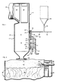
- Fig. 1 is a vertical sectional view of an embodiment of an apparatus employed in accordance with the present invention; and
- Fig. 2 is an enlarged, fragmentary view of a portion of the apparatus shown in Fig. 1.
- Referring initially to Fig. 1, indicated generally at 10 is an embodiment of a boiler for combusting fuel to heat water to generate steam. The embodiment illustrated in Fig. 1 is vertically disposed. Boiler 10 comprises a combustion chamber indicated generally at 11 having first and
second combustion zones heat exchange walls 24 on the opposite side of which water is flowed, in a conventional manner, for absorbing heat from combustion chamber 11 generated therein by a combustion reaction. For example,heat exchange walls 24 can be a ring of vertical tubes through which water is flowed. - Communicating with
first combustion zone 12 are a plurality of vertically spacednozzle first combustion zone 12. Aline 15 communicates with each ofnozzles respective branch lines adjacent nozzles respective ports pressurized wind box 19 in turn communicating with the upstream end of aconduit 20 for introducing preheated air intowind box 19. - Communicating with an upstream end of
wind box 19 is aconduit 25 for conducting preheated air into awind box extension 26 communicating with a series of peripherally spacedtubular ports 27 for introducing tertiary air intosecond combustion zone 13. Only oneport 27 is shown in Fig. 1, but there are typically six such ports at the same vertical level.Second combustion zone 13 andtubular port 27 are spaced above all of the nozzles 16-18 and are relatively remote therefrom in a downstream direction. - Disposed substantially coaxially within
tubular port 27 is apipe 28 terminating at an opendownstream end 29.Pipe 28 is employed to inject limestone particles into the stream of tertiary air as the stream enterssecond combustion zone 13. There is no premixing of the limestone particles inpipe 28 with tertiary air before the particles entersecond combustion zone 13 atpipe end 29. - In a typical embodiment employing six peripherally spaced tertiary air por
ts 27, apipe 28 may be associated with four of the six ports. Introducing the limestone particles through four peripherally spacedports 27 assists in the widespread horizontal distribution of limestone particles insecond zone 13 compared to introduction through only one or two ports. - The limestone particles are stored in a
hopper 30 which feeds into aconduit 31 extending downwardly fromhopper 30 toline 28. Communicating withpipe 28 is aconduit 32 through which flows a transport gas for transporting the limestone particles fromhopper 30 throughpipe 28. - Limestone particles are the preferred material for producing lime particles by calcination in the combustion chamber. Other finely divided materials, which form lime particles upon exposure to the heat in the second combustion zone, may be employed. These include calcium hydroxide, Ca(OH)₂, and dolomite, CaMg(CO₃)₂, which calcines to produce a reaction product which is about 80 wt.% lime and 20 wt.% MgO. The MgO does not usually participate in SO₂ removal to any substantial degree in the method of the present invention.
- Combustion reaction gases are generated in combustion chamber 11 and flow upwardly (downstream) past primary and
secondary superheaters conduit 37 which communicates with conventional apparatus (not shown) for removing particulates from the flue gas and with conventional heat exchange apparatus (not shown) for preheating the air which is eventually flowed throughconduit 20 andline 15. Eventually, the cooled, cleaned flue gases are exhausted into the atmosphere through a stack (not shown). - Located at the bottom of boiler 10 is an
opening 38 for removing ash particles generated during the combustion reaction within chamber 11. - In accordance with the present invention, a mixture of primary air and a sulfur-containing fuel are flowed through
line 15 into nozzles 16-18. The sulfur- containing fuel may be coal, fuel oil, or coke oven gas, for example. The total amount of primary, secondary and tertiary air is in excess of the stochiometric amount required to combust the fuel introduced through nozzles 16-18. Typically, there is enough air to provide an oxygen content about 3% greater than the stoichiometric quantity required to combust all the fuel. - A major portion of the combustion air is introduced into
first combustion zone 12, through nozzles 16-18 and ports 21-23, together with or closely adjacent the fuel to at least partially combust the fuel. A second portion of air, constituting the remainder of the air or tertiary air, is introduced as overfire air into the combustion chamber atsecond zone 13 throughport 27. - At least some combustion occurs in
first zone 12, and the contents of the first zone including the combustion reaction products as well as uncombusted fuel, if any, flow downstream fromfirst zone 12 throughsecond zone 13. - Flames generated in
first combustion zone 12 extend downstream towardssecond combustion zone 13 as a flame front which is not uniform, containing peak flame temperatures which are higher than other temperatures across the flame front. - In order to buffer the peak flame temperatures and provide a relatively uniform flame front in
second combustion zone 13, the second portion of air is introduced at a location (port 27) and with a velocity (e.g 5000 ft/min.) (1,524 m/min.) for accomplishing these purposes. The resulting uniform flame front, in which peak flame temperatures have been buffered, is indicated at 42 in Fig. 2. The minimum velocity of the second portion of air should be about 2,500 ft/min. (762 m/min.) in order to produce these results. - The gases moving through
second combustion zone 13 include sulfur dioxide. In order to convert the sulfur dioxide to calcium sulfate, f inely divided limestone particles are introduced intosecond zone 13 together with and under the urging of the second portion of air. As shown in Fig. 2, a stream oflimestone particles 33 enterssecond combustion zone 13 at the downstreamopen end 29 ofpipe 28. The second portion of air enteringsecond combustion zone 13 atport 27 distributes the limestone particles throughout the gases flowing downstream through the second zone. The limestone particles entering the second zone are flash calcined downstream offirst zone 12 to produce particles of lime which reacts with at least part of any sulfur dioxide present, in the presence of oxygen from that part of the air which is in excess of that stochiometrically required to react with the fuel, to produce calcium sulfate. - The contents of
second combustion zone 13 are flowed downstream away from the first andsecond combustion zones - The average temperature in
first combustion zone 12 exceeds the sintering temperature of the limestone and lime particles (1316°C or 2400°F). The location and velocity of the second portion of air is such as to provide an average processing temperature range, downstream offirst combustion zone 12 which is below the sintering temperature for the limestone and lime particles as well as being below the temperature at which calcium sulfate decomposes into lime and gaseous oxides of sulfur (1349°C or 2460°F). Sintering is undesirable because it decreases the surface area of the resulting lime particles which reduces the reactivity thereof. Therefore, the temperature insecond zone 13 and downstream from there is high enough for flash calcination of the finely divided limestone particles but low enough to avoid sintering of the resulting lime particles. - The average processing temperature range is about 1600°-2400°F (871°-1316°C). This is high enough and prevails long enough for the lime, produced downstream of
first combustion zone 12, to react with a desired amount of sulfur dioxide gas during the time in which the lime and the sulfur dioxide gas are subjected to that temperature range. The lime and sulfur dioxide gas are subjected to the average processing temperature range for more than 0.5 seconds, preferably at least 1.5 seconds. The limestone particles are flash calcined to particles of lime in less than 0.1 second, so that the rest of the time during which the particles are subjected to the temperature range 1600°-2400°F (871°-1316°C) is time in which a reaction with sulfur dioxide can occur. Below 1600°F (871°C) the reactions which convert sulfur dioxide to calcium sulfate are too slow to be practicable. The length of time in which sulfur dioxide and lime are subjected to the desired average processing temperature range of 1600°-2400°F (871°-1316°C) can be increased by reducing the amount of excess air (e.g. from 3% to 1.5%), by reducing the rate at which steam is generated (i.e. the rate at which heat is exchanged through thewalls 24 ofcombustion chamber 12 or superheaters 35 and 36), by reducing the velocity of the gases flowing downstream from the combusiton chamber, etc. - As noted above, the limestone particles introduced into
second combustion zone 13 are transported up to the combustion zone by the transport gas fromconduit 32. Before enteringsecond combustion zone 13, the limestone particles have imparted thereto by the transport gas a velocity sufficient to carry the limestone particles up to the second zone but intentionally insufficient to distribute the limestone particles across the second zone. This minimizes the amount of air introduced intopipe 28 and thereby the amount of extraneous air introduced into the combustion chamber, an advantage which will be discussed more fully below. - Distribution of the limestone particles across the second zone is accomplished by the high velocity air introduced at
port 27. This air has a velocity which not only buffers the flames fromfirst combustion zone 12 but also aspirates the lim estone particles into, and distributes them across, the second zone. Referring to Fig. 2, distribution is enhanced by theturbulence 43 caused at least in part when the high velocity second portion of air is directed laterally across the second zone. - In a preferred embodiment, the limestone particles are carried up to
second zone 13, i.e. up to openend 29 inpipe 28, under dense phase transport. This is accomplished by mixing the limestoneparticles entering pipe 28 fromconduit 31 with transporting air in an amount which imparts dense phase transport. The minimum solids to gas ratio for dense phase transport is about 20 to 1, and a typical ratio employed in accordance with the present invention is about 90 to 1. The minimum velocity required to provide a dense phase transport of limestone particles having a maximum particle size of minus 100 mesh on a wet screen basis is about 300 ft/min. (91 m/min.). A typical gas pressure inconduit 32 is 15-30 psig (103.5-207 kPa). - The term "wet screen basis" reflects the fact that the limestone particles have been subjected to water before screening, and this enables the screening out of particles which have undergone agglomeration as a result of being subjected to water.
- The velocity with which the limestone particles are conveyed thorugh
pipe 28 to openpipe end 29 can vary over a wide range, e.g. 300 ft/min (91 m/min.) to 10,000 ft/min. (3,048 m/min.), with little effect on the limestone particle distribution inzone 13. This is because the tertiary air introduced atport 27, typically at a velocity of 5,000 ft/min (1524 m/min.), performs the totality of the limestone particles distribution function inzone 13, and this is so even when the velocity inpipe 28 is 10,000 ft/min. (3,048 m/min.). The velocity of the particles inpipe 28 plays virtually no role in the distribution of limestone particles inzone 13. The relative volume of air moving throughpipe 28 is insubstantial compared to the volume of tertiaryair entering zone 13 atport 27, no matter the velocity inpipe 28. Although not apparent from the drawing, in which the diameter ofpipe 28 is exaggerated for illustrative purposes, the cross-sectional area of elements 25-27, through which the tertiary air is transported, is very much greater than that ofpipe 28. Typically, there are sixtertiary air ports 27 each having a diameter of about 9 inches (229 cm) while there are only fourpipes 28 each having a diameter of 1.5 inches (38 cm). The total cross-sectional area of the latter is less than 2% of the total cross-sectional area of the former. Accordingly, one may employ a velocity in pipe 28 a low as possible, e.g. merely enough to provide dense phase transport, and it will make essentially no difference from the standpoint of particle distribution inzone 13, compared to the distribution obtained when employing a greater velocity inpipe 28. - Substantially no extraneous air is employed for introducing and distributing the limestone particles into the combustion chamber. This is because the second portion of air, which performs the limestone-introduction and distribution functions at
port 27 was normally employed for combustion purposes in the absence of limestone injection. As used herein, "extraneous" air refers to air in additon to that normally employed for combustion purposes. The amount of air used for dense phase transport of the limestone particles inpipe 28 is insignificant compared to the combined major and second air portions introduced at nozzles 16-18, ports 21-23 andport 27. Because essentially all the air introduced into the combustion chamber is no more than just that amount of air which is normally introduced for combustion purposes, there is a minimization, if not a total elimination of any adverse effect the introduction of the limestone particles under the urging of air could have on the steam generating capabilities of the fuel and combustion air, a drawback which could occur if extraneous air were used. - As noted above, there is no premixing of the limestone particles with the second portion of combustion air before they enter
second combustion zone 13 at 27 and 29 respectively. Therefore, the second portion of combustion air may be introduced intosecond zone 13 at whatever high velocity is necessary to provide the desired buffering, turbulence and particle mixing and distributing effects. There are no erosion or plugging problems inconduit 25,extension 26 orports 27 because no limestone particles flow therethrough. The velocity and volume of combustion air introduced atports 27 is undicated by limestone transporting considerations. - The limestone particles move through
conduit 28 in dense phase transport at a relatively very slow speed, e.g. about 360 ft/min. (110 m/min.), for example. At such low speeds, there is relatively no erosion inpipe 28, and the likelihood of plugging inpipe 28 is reduced substantially. The likelihood of plugging increases with the speed of particle travel. The velocity of the second air portion is 2500-5,000 ft/min. (762-1524 m/min), so that the speed of particle travel inconduit 25 would be much faster than inpipe 28, thereby substantially increasing the likelihood of pluggage if there were premixing. - When the limestone particles move in dense phase transport, e.g. at a ratio of solids to gas of 90-100 to 1 or higher, the stream of limestone particles may be very accurately divided into substreams merely by controlling the cross-sectional area of the substream conduits. For example, a stream in dense phase transport may be divided into two equal substreams by providing the two substream conduits with equal cross-sectional areas. This feature is not available with dilute phase transport.
- As noted above, a factor which effects the conversion of sulfur dioxide to calcium sulfate is the reactivity of the lime particles. The greater the surface area of lime, the greater the reactivity. In accordance with the present invention, the desired amount of surface area is provided by supplying limestone particles smaller than 100 mesh (less than 150 microns) on a wet screen basis. Preferably, the limestone particles have a size, in the range between about 5 microns and minus 100 mesh, on a wet screen basis, sufficient to provide the reaction required to eliminate the sulfur dioxide gas to the extent required. Typically, the limestone particles comprise about 70% smaller than 200 mesh (less than 75 microns), on a wet screen basis.
- If sufficient reactivity is not obtained for a given limestone particle size, reactivity may be increased by reducing the particle size, all other factors being constant. Reducing the particle size increases the surface area of the lime and results in a better distribution of the particles, but it also increases the expense. Typically, one employs the coarsest particle size, in the range of about 5 microns to minus 100 mesh, that will give the desired amount of SO₂ removal.
- The amount of limestone injected depends upon the amount of sulfur dioxide which has to be converted to calcium sulfate and this depends upon the initial and final desired sulfur dioxide contents of the flue gases. Generally speaking, an increase in the calcium to sulfur ratio increases the sulfur dioxide removal efficiency, although not on a linear basis.
- Although the second portion of air entering
second combustion zone 13 atport 27 has been preheated, it is relatively cool compared to the temperatures of thegas entering zone 13 fromzone 12. The limestone particles enter the second zone within the stream of air constituting the second air portion. - As previously noted, there are peak temperatures, in the contents of the first zone flowing downstream toward the second zone, which are high enough to cause sintering of the limestone particles. The second portion of air, entering through
port 27, cushions the limestone particles from the peak temperatures described in t he preceding sentence to prevent sintering of the limestone particles. - There are other advantages to injecting limestone into the combustion chamber of the boiler, in addition to those described above. During operation of a boiler, deposits of soot, etc. normally form on the inside surface of the boiler walls, e.g. at
second combustion zone 13. It is conventional practice to remove these deposits by employing a procedure known as soot blowing wherein steam is blow through the boiler, and this cleans off the deposits. This procedure is employed peridically during operation of the boiler (e.g. for one-half to one hour, three to six times per day). When limestone is injected intozone 13 at 27, some of the lime formed inzone 13 is unavoidably incorporated into the deposits. Lime makes the deposits more friable and easier to clean off. - Moreover, as the deposits are being removed from the boiler walls by soot blowing, lime is being introduced from the deposits, into
second combustion zone 13 and above, resulting in a lowering of the SO₂ content because of the reaction between the SO₂ and the lime from the cleaned-off deposits. SO₂ removal is increased by 5-10% (on a 100% basis) during soot blowing. In other words, if the SO₂ is 40% removed before soot blowing, then it will be 45-50% removed during soot blowing. This enables one to reduce the limestone injected at 29 during the soot blowing period without a corresponding reduction in SO₂ removal. - Furthermore, during periods when limestone injection at 29 is temporarily suspended, SO₂ removal will continue because of the lime content of the deposits on the inside surface of the boiler walls. More particularly, SO₂ is absorbed into the deposits and reacts with the lime therein to form calcium sulfate (CaSO₄) there. This can continue for up to 3 days, with decreasing SO₂ removal, starting at about 5-7% SO₂ removal at the beginning of the shut down period for limestone injection. Therefore, should there be a need to shut down the limestone injecting apparatus, e.g. for maintenance, servicing or the like, SO₂ removal will continue for awhile, at least to some extent.
- One should control soot blowing during the period when limestone injection is shut down, to retain the deposits or parts thereof, and their SO₂-absorbing function, during that period. For example, after SO₂ absorption into a deposit has occurred for awhile, there will be a buildup of calcium sulfate in an outer layer of the deposit. Soot blowing of reduced longevity, sufficient to remove only this outer layer and expose a fresh outer layer devoid of calcium sulfate would then be desirable. It would be undesirable to remove the entire deposit in one soot blowing operation. When the SO₂-absorbing properties of the innermost layer of the deposits has been depleted, removal of the deposits can be completed, with soot blowing.
- Another advantage arising from limestone injection is the elimination of acids from the entire boiler system, both the combustion chamber and downstream components. Acids can form as a result of the combustion reaction. These acids include primarily sulfuric acid but also hydrochloric and nitric acids. Acids are undesirable because, if they precipitate out of the flue gases somewhere in the system, they can severely corrode the system's components, among other things. It has been conventional in the past to operate the boiler system in such a manner as to produce a flue gas exhaust temperature above the dew point of the acids, e.g. a stack exhaust temperature in the range 300°-350°F (148°-177°C). This prevents the acids from precipitating out of the flue gases anywhere in the system, but it is accomplished at the expense of heat utilization elsewhere, e.g. for generating steam.
- Limestone injection forms lime which neutralizes the acids. Therefore, acid precipitation from the flue gases is not a problem, and one need not maintain the fl ue gases at an exhaust temperature above the dew point of the acids. As a result, the system can be operated with a lower stack exhaust temperature, e.g. 110°-250°F (43°-121°C), and more heat can be extracted from the flue gases to generate steam.
- The foregoing detailed description has been given for clearness of understanding only, and no unnecessary limitations should be understood therefrom, as modifications will be obvious to those skilled in the art.
Claims (31)
introducing a sulfur-containing fuel into a first zone in an enclosed combustion chamber;
introducing a first portion of air into said first zone at least closely adjacent said fuel to at least partially combust said fuel and produce combustion reaction gases containing sulfur dioxide;
introducing a second portion of air into said combustion chamber at a second zone spaced relatively remotely from said first zone;
flowing the contents of said first zone downstream through said second zone;
controlling the location at which said second portion of air is introduced, and the velocity thereof, to buffer the peak flame temperature and provide a relatively uniform flame front in said second zone;
providing finely divided particles of a material which forms lime upon exposure to the heat in said second zone;
introducing said particles into said second zone together with and under the urging of said second portion of air, without premixing said particles and said second portion of air before they enter said second zone;
and employing said second portion of air to distribute said particles throughout the gases flowing downstream through the second zone.
flowing the contents of said second zone in a downstream direction away from said first and second zones;
and flash calcining said particles of material downstream of said first zone to produce particles of lime (CaO) which reacts with at least part of any SO₂ present to produce calcium sulfate (CaSO₄) in said combustion chamber.
the average temperature in said first zone exceeds the sintering temperature of lime; and
said controlling step provides an average processing temperature range, downstream of said first zone, which is below the sintering temperature for said lime particles and below the temperature at which said calcium sulfate decomposes into lime and gaseous oxides of sulfur;
said average processing temperature range being high enough and prevailing long enough to react the lime produced downstream of said first zone with the desired amount of SO₂ gas during the time in which said lime and said SO₂ gas are subjected to said average processing temperature.
said average processing temperature range is about 1600°-2400°F (871-1316°C).
said lime and said SO₂ gas are subjected to said average processing temperature range for more than 0.5 second.
said lime and said SO₂ gas are subjected to said average processing temperature range for at least about 1.5 seconds.
said sulfer-containing fuel is at least one of the group comprising finely divided coal particles, coke oven gas and fuel oil.
transporting said particles of material up to said second zone;
and aspirating said particles of material into said s econd zone by the action of the second portion of air as the latter is introduced into the second zone.
imparting to said particles of material, before the second zone, a velocity sufficient to flow the particles of material up to the second zone but insufficient to distribute the particles across the second zone.
flowing the particles of material up to said second zone under dense phase transport.
mixing said particles of material with transporting air in an amount which will provide dense phase transport.
said particles of material have a flow velocity up to said second zone of at least about 300 ft/min. (91 m/min).
said second portion of air is introduced into said second zone at a veloctiy of at least about 2,500 ft/min (1762 m/min.) so as to aspirate the particles of material into the second zone.
causing tubulence by the introduction of said second portion of air into the second zone to aid in the distribution of the particles of material throughout the second zone.
the velocity of the second portion of air as it enters the second zone is at least about 2,500 ft/min. (762 m/min.);
and said particles of material are introduced into the second zone without the use of extraneous air.
said particles of material are smaller than 100 mesh on a wet screen basis.
said particles of material have a size, in the range between about 5 microns and minus 100 mesh, on a wet screen basis, sufficient to provide the reaction required to eliminate SO₂ gas to the extent desired.
said fuel is particulate coal;
said first portion of air is divided into two parts, one of which is mixed with said coal for injection with the coal into said first zone:
the other of said two parts of air being injected into said first zone alongside said mixture of particulate coal and the one part of air;
and said method comprises preheating essentially all of said air entering said combustion chamber.
said second portion of air enters said second zone initially as a stream of air which is relatively cool compared to the temperature in said second zone;
and said particles of material enter said second zone within said stream of air constituting said second portion.
there are peak temperatures, in the contents of said first zone flowing downstream through said second sone, which are high enough to cause sintering of said particles;
and said second portion of air cushions said particles from said peak temperature to prevent sintering of the particles.
said combustion chamber has inside wall surfaces, deposits form on said inside wall surfaces in said second zone during the combustion operation, lime formed from said particles of material is incorporated into said deposits, soot blowing is employed to remove said deposits, and lime from said deposits is introduced into said combustion chamber as a result of said soot blowing:
said method comprising the step of reducing the amount of said lime-forming material introduced into said second zone, during said soot blowing step, without reducing substantially the decrease, in sulphur dioxide content, obtained before the soot blowing step.
said combustion chamber is part of a combustion system.
acids are formed in said combustion system as a result of the comusting of said fuel;
said acids are neutralised by said lime;
and said combustion reaction gases are exhausted from the combustion system at a temperature below the dew point of said acids.
said fuel gases are exhausted from the combustion system at a temperature below 250°F (121° C).
said combustion chamber has inside wall surfaces, deposits form on said inside wall surfaces in said second zone during the combustion operation, and lime formed from said particles of material is incorporated into said deposits;
said step of introducing said lime forming material is temporarily suspended for a period of time, after it has been performed for awhile;
at least some of said SO₂ is absorbed by the lime in said deposits during at least the early part of said temporary suspension period;
and soot blowing is deferred while said SO₂ is being absorbed into said deposits.
after deferring said soot blowing for a period of time, soot blowing is then only partially performed, to remove only an outer layer of said deposits and expose a new deposit outer layer for absorption of SO₂.
combusting a sulfur-containing fuel with air in a combustion chamber, having inside wall surfaces, to produce combustion reaction gases containing sulfur dioxide (SO₂);
introducing, into said combustion chamber, finely divided particles of a material which forms lime upon exposure to the heat in said combustion chamber;
reacting said lime with said sulfur dioxide in the combustion reaction gases, in said combustion chamber, to decrease the sulfur dioxide content of said gases;
forming deposits on the inside wall surfaces of said combustion chamber during the combustion operation;
incorporating lime from said particles of material into said deposits;
soot blowing, after there has been an accumulation of said deposits, to remove said deposits from said inside wall surfaces;
and reducing the amount of said lime-forming material introduced into the combustion chamber, during said soot blowing step, without reducing substantially the decrease in sulfur dioxide content obtained before the soot blowing step.
combusting a sulfur-containing fuel with air in said combustion chamber to produce combustion reaction gases containing sulfur dioxide (SO₂);
introducing, into said combustion chamber, finely divided particles of a material which forms lime upon exposure to the heat in said combustion chamber;
forming acids in said combustion system as a result of said combusting step;
neutralizing said acids with said lime;
and exhausting said combustion reaction gases from said combustion system at a temperature below the dew point of said acids.
said flue gases are exhausted from the combustion system at a temperature below 250°F (121°C).
combusting a sulfur-containing fuel with air in a combustion chamber, having inside wall surfaces, to produce combustion reaction gases containing sulfur dioxide;
introducing, into said combustion chamber, finely divided particles of a material which forms lime upon exposure to the heat in said combustion chamber;
forming deposits on the inside wall surfaces of said combustion chamber during the combustion operation;
incorporating lime from said particles of material into said deposits;
temporarily suspending said introducing step for a period of time, after it has been performed for awhile;
absorbing at least some of said SO₂ by the lime in said deposits during at least the early part of said temporary suspension period;
and deferring soot blowing while said SO₂ is being absorbed into said deposits.
after deferring said soot blowing for a period of time, soot blowing is then only partially performed, to remove only an outer layer of said deposits and expose a new deposit outer layer for absorption of SO₂.
a nozzle for introducing fuel and primary air into said chamber;
means for introducing fuel into said nozzle;
means for introducing primary air into said nozzle;
means, located adjacent said fuel nozzle, for introducing secondary air into said chamber;
tubular means for introducing a stream of tertiary air into said chamber at a location spaced relatively remotely from said nozzle;
and pipe means for injecting finely divided particles of material into said stream of tertiary air as the stream enters said chamber, without premixing said particles and said stream before they enter said chamber;
said pipe means being disposed substantially coaxially within said tubular means and terminating at an open downstream end, there being no communication between said pipe means and said tubular means upstream of said open downstream end.
Priority Applications (2)
| Application Number | Priority Date | Filing Date | Title |
|---|---|---|---|
| EP91112744A EP0461678B1 (en) | 1986-07-14 | 1987-07-10 | Method and apparatus for reducing sulphur dioxide content in flue gases |
| GR960401580T GR3020405T3 (en) | 1986-07-14 | 1996-06-12 | Method and apparatus for reducing sulphur dioxide content in flue gases |
Applications Claiming Priority (4)
| Application Number | Priority Date | Filing Date | Title |
|---|---|---|---|
| US88546386A | 1986-07-14 | 1986-07-14 | |
| US885463 | 1986-07-14 | ||
| US464487A | 1987-01-20 | 1987-01-20 | |
| US4644 | 1987-01-20 |
Related Child Applications (1)
| Application Number | Title | Priority Date | Filing Date |
|---|---|---|---|
| EP91112744.7 Division-Into | 1987-07-10 |
Publications (3)
| Publication Number | Publication Date |
|---|---|
| EP0253324A2 true EP0253324A2 (en) | 1988-01-20 |
| EP0253324A3 EP0253324A3 (en) | 1988-05-18 |
| EP0253324B1 EP0253324B1 (en) | 1996-03-13 |
Family
ID=26673281
Family Applications (2)
| Application Number | Title | Priority Date | Filing Date |
|---|---|---|---|
| EP87109975A Expired - Lifetime EP0253324B1 (en) | 1986-07-14 | 1987-07-10 | Method and apparatus for reducing sulphur dioxide content in flue gases |
| EP91112744A Expired - Lifetime EP0461678B1 (en) | 1986-07-14 | 1987-07-10 | Method and apparatus for reducing sulphur dioxide content in flue gases |
Family Applications After (1)
| Application Number | Title | Priority Date | Filing Date |
|---|---|---|---|
| EP91112744A Expired - Lifetime EP0461678B1 (en) | 1986-07-14 | 1987-07-10 | Method and apparatus for reducing sulphur dioxide content in flue gases |
Country Status (9)
| Country | Link |
|---|---|
| EP (2) | EP0253324B1 (en) |
| JP (1) | JPH0743094B2 (en) |
| AT (2) | ATE138284T1 (en) |
| AU (2) | AU603366B2 (en) |
| CA (2) | CA1309571C (en) |
| DE (2) | DE3751817T2 (en) |
| ES (2) | ES2083948T3 (en) |
| GR (2) | GR3019674T3 (en) |
| NO (2) | NO301807B1 (en) |
Cited By (7)
| Publication number | Priority date | Publication date | Assignee | Title |
|---|---|---|---|---|
| WO1990003837A1 (en) * | 1988-10-14 | 1990-04-19 | Oy Finnpulva Ab | Method for binding of the sulfur compounds formed in a pulverized-coal boiler |
| EP0430144A1 (en) * | 1989-11-27 | 1991-06-05 | MARTIN GmbH für Umwelt- und Energietechnik | Method and apparatus for reducing the concentration of nitrogen oxides in waste gases of combustion processes |
| WO1992003211A1 (en) * | 1990-08-17 | 1992-03-05 | Fritz Schoppe | Process and device for complete, dry desulphuration of combustion waste gases containing so2 and dust |
| US20100209858A1 (en) * | 2006-01-26 | 2010-08-19 | Frenette Henry E | Combustion system for atomizing fuel mixture in burner box |
| US9657938B2 (en) | 2014-02-07 | 2017-05-23 | Eugene R. Frenette | Fuel combustion system |
| US9874349B2 (en) | 2015-04-03 | 2018-01-23 | Eugene R. Frenette | Fuel combustion system |
| CN110715287A (en) * | 2019-10-29 | 2020-01-21 | 辽宁绿源能源环保科技集团有限责任公司 | Layer-combustion boiler structure and boiler desulfurization and denitrification method |
Families Citing this family (4)
| Publication number | Priority date | Publication date | Assignee | Title |
|---|---|---|---|---|
| JPH03161016A (en) * | 1989-11-20 | 1991-07-11 | Hitachi Zosen Corp | Apparatus for mixing fine powder with combustion gas in dispersed state |
| JP5456226B2 (en) * | 2005-07-14 | 2014-03-26 | 出光興産株式会社 | Methods for controlling the elution of harmful trace elements |
| JP2008169338A (en) * | 2007-01-12 | 2008-07-24 | Chugoku Electric Power Co Inc:The | Method of reducing unburned coal |
| CN111054091B (en) * | 2019-12-31 | 2022-01-04 | 宁夏丰华生物科技有限公司 | Gas-liquid separation device for processing thionyl chloride rectification |
Citations (8)
| Publication number | Priority date | Publication date | Assignee | Title |
|---|---|---|---|---|
| US3481289A (en) * | 1968-05-13 | 1969-12-02 | Central Res Inst Elect | Method for removing sulfur dioxide from flue gases of a combustion furnace |
| DE3206409A1 (en) * | 1982-02-23 | 1983-09-01 | Rudolf Dr. 6800 Mannheim Wieser | Water-tube boiler having flue gas desulphurisation |
| DE3428502A1 (en) * | 1983-08-16 | 1985-03-07 | Gernot Prof. Dipl.-Ing. Dr. Graz Staudinger | METHOD AND DEVICE FOR DRY DESULFURING EXHAUST GAS |
| EP0134040A1 (en) * | 1983-08-26 | 1985-03-13 | STEIN INDUSTRIE Société Anonyme dite: | Method for the injection of a pulverulent material into a combustion chamber of a boiler, and device for carrying out this method |
| EP0156784A2 (en) * | 1984-03-30 | 1985-10-02 | Norrköpings Kraft AB | A method of reducing sulphur-oxide and nitrogen-oxide emission when burning solid fuel on travelling grates |
| GB2157192A (en) * | 1984-04-10 | 1985-10-23 | Hitachi Shipbuilding Eng Co | Method of purifying exhaust gas |
| DE3441726A1 (en) * | 1984-11-15 | 1986-05-22 | L. & C. Steinmüller GmbH, 5270 Gummersbach | METHOD FOR MIXING INTENSIVE MIXTURES OF ADDITIVES INTO THE FIREPLACE TO BIND THE SULFUR |
| US4655148A (en) * | 1985-10-29 | 1987-04-07 | Combustion Engineering, Inc. | Method of introducing dry sulfur oxide absorbent material into a furnace |
Family Cites Families (2)
| Publication number | Priority date | Publication date | Assignee | Title |
|---|---|---|---|---|
| JPS58156104A (en) * | 1982-03-10 | 1983-09-17 | Hitachi Zosen Corp | Desulfurizing method for inside of furnace in solid combustion furnace |
| US4602573A (en) * | 1985-02-22 | 1986-07-29 | Combustion Engineering, Inc. | Integrated process for gasifying and combusting a carbonaceous fuel |
-
1987
- 1987-06-19 CA CA000540139A patent/CA1309571C/en not_active Expired - Fee Related
- 1987-07-09 AU AU75382/87A patent/AU603366B2/en not_active Ceased
- 1987-07-10 EP EP87109975A patent/EP0253324B1/en not_active Expired - Lifetime
- 1987-07-10 ES ES87109975T patent/ES2083948T3/en not_active Expired - Lifetime
- 1987-07-10 DE DE3751817T patent/DE3751817T2/en not_active Expired - Fee Related
- 1987-07-10 EP EP91112744A patent/EP0461678B1/en not_active Expired - Lifetime
- 1987-07-10 ES ES91112744T patent/ES2086440T3/en not_active Expired - Lifetime
- 1987-07-10 AT AT91112744T patent/ATE138284T1/en active
- 1987-07-10 AT AT87109975T patent/ATE135252T1/en not_active IP Right Cessation
- 1987-07-10 DE DE3751733T patent/DE3751733T2/en not_active Expired - Fee Related
- 1987-07-13 NO NO872908A patent/NO301807B1/en not_active IP Right Cessation
- 1987-07-14 JP JP62175805A patent/JPH0743094B2/en not_active Expired - Lifetime
-
1992
- 1992-05-25 CA CA000616387A patent/CA1321464C/en not_active Expired - Fee Related
- 1992-11-16 AU AU28424/92A patent/AU640577B2/en not_active Ceased
-
1996
- 1996-04-19 GR GR960401051T patent/GR3019674T3/en unknown
- 1996-06-12 GR GR960401580T patent/GR3020405T3/en unknown
-
1997
- 1997-09-05 NO NO974087A patent/NO303269B1/en not_active IP Right Cessation
Patent Citations (8)
| Publication number | Priority date | Publication date | Assignee | Title |
|---|---|---|---|---|
| US3481289A (en) * | 1968-05-13 | 1969-12-02 | Central Res Inst Elect | Method for removing sulfur dioxide from flue gases of a combustion furnace |
| DE3206409A1 (en) * | 1982-02-23 | 1983-09-01 | Rudolf Dr. 6800 Mannheim Wieser | Water-tube boiler having flue gas desulphurisation |
| DE3428502A1 (en) * | 1983-08-16 | 1985-03-07 | Gernot Prof. Dipl.-Ing. Dr. Graz Staudinger | METHOD AND DEVICE FOR DRY DESULFURING EXHAUST GAS |
| EP0134040A1 (en) * | 1983-08-26 | 1985-03-13 | STEIN INDUSTRIE Société Anonyme dite: | Method for the injection of a pulverulent material into a combustion chamber of a boiler, and device for carrying out this method |
| EP0156784A2 (en) * | 1984-03-30 | 1985-10-02 | Norrköpings Kraft AB | A method of reducing sulphur-oxide and nitrogen-oxide emission when burning solid fuel on travelling grates |
| GB2157192A (en) * | 1984-04-10 | 1985-10-23 | Hitachi Shipbuilding Eng Co | Method of purifying exhaust gas |
| DE3441726A1 (en) * | 1984-11-15 | 1986-05-22 | L. & C. Steinmüller GmbH, 5270 Gummersbach | METHOD FOR MIXING INTENSIVE MIXTURES OF ADDITIVES INTO THE FIREPLACE TO BIND THE SULFUR |
| US4655148A (en) * | 1985-10-29 | 1987-04-07 | Combustion Engineering, Inc. | Method of introducing dry sulfur oxide absorbent material into a furnace |
Non-Patent Citations (1)
| Title |
|---|
| Perry's Chemical Engineers Handbook, 5th Edition, McGraw Hill, New York, 1973 pages 5-46, 5-47 * |
Cited By (10)
| Publication number | Priority date | Publication date | Assignee | Title |
|---|---|---|---|---|
| WO1990003837A1 (en) * | 1988-10-14 | 1990-04-19 | Oy Finnpulva Ab | Method for binding of the sulfur compounds formed in a pulverized-coal boiler |
| EP0430144A1 (en) * | 1989-11-27 | 1991-06-05 | MARTIN GmbH für Umwelt- und Energietechnik | Method and apparatus for reducing the concentration of nitrogen oxides in waste gases of combustion processes |
| WO1992003211A1 (en) * | 1990-08-17 | 1992-03-05 | Fritz Schoppe | Process and device for complete, dry desulphuration of combustion waste gases containing so2 and dust |
| CN1034788C (en) * | 1990-08-17 | 1997-05-07 | 弗里兹·司克普 | Process and apparatus for removal of sulfur from dust-containing flue gas |
| US20100209858A1 (en) * | 2006-01-26 | 2010-08-19 | Frenette Henry E | Combustion system for atomizing fuel mixture in burner box |
| US9657938B2 (en) | 2014-02-07 | 2017-05-23 | Eugene R. Frenette | Fuel combustion system |
| US9874349B2 (en) | 2015-04-03 | 2018-01-23 | Eugene R. Frenette | Fuel combustion system |
| CN110715287A (en) * | 2019-10-29 | 2020-01-21 | 辽宁绿源能源环保科技集团有限责任公司 | Layer-combustion boiler structure and boiler desulfurization and denitrification method |
| CN112460586A (en) * | 2019-10-29 | 2021-03-09 | 辽宁绿源能源环保科技集团有限责任公司 | Desulfurization and denitrification method for layer-combustion boiler |
| CN112460586B (en) * | 2019-10-29 | 2022-12-13 | 绿源能源环境科技集团有限公司 | Desulfurization and denitrification method for layer-combustion boiler |
Also Published As
| Publication number | Publication date |
|---|---|
| CA1309571C (en) | 1992-11-03 |
| NO303269B1 (en) | 1998-06-22 |
| ES2083948T3 (en) | 1996-05-01 |
| GR3020405T3 (en) | 1996-09-30 |
| ATE135252T1 (en) | 1996-03-15 |
| AU603366B2 (en) | 1990-11-15 |
| DE3751817T2 (en) | 1996-09-26 |
| EP0461678B1 (en) | 1996-05-22 |
| JPS6325403A (en) | 1988-02-02 |
| NO301807B1 (en) | 1997-12-15 |
| CA1321464C (en) | 1993-08-24 |
| NO872908D0 (en) | 1987-07-13 |
| GR3019674T3 (en) | 1996-07-31 |
| NO872908L (en) | 1988-01-15 |
| DE3751733D1 (en) | 1996-04-18 |
| EP0461678A1 (en) | 1991-12-18 |
| NO974087L (en) | 1997-09-05 |
| ES2086440T3 (en) | 1996-07-01 |
| NO974087D0 (en) | 1997-09-05 |
| DE3751817D1 (en) | 1996-06-27 |
| AU640577B2 (en) | 1993-08-26 |
| AU2842492A (en) | 1993-01-14 |
| EP0253324A3 (en) | 1988-05-18 |
| EP0253324B1 (en) | 1996-03-13 |
| JPH0743094B2 (en) | 1995-05-15 |
| ATE138284T1 (en) | 1996-06-15 |
| AU7538287A (en) | 1988-01-21 |
| DE3751733T2 (en) | 1996-08-08 |
Similar Documents
| Publication | Publication Date | Title |
|---|---|---|
| US5048431A (en) | Method and apparatus for reducing sulfur dioxide content in flue gases | |
| US4555996A (en) | Method for reduction of sulfur products in the exhaust gases of a combustion chamber | |
| CA2133638C (en) | Desulphurization of carbonaceous fuel | |
| EP0461678B1 (en) | Method and apparatus for reducing sulphur dioxide content in flue gases | |
| US20100263577A1 (en) | Pollution abatement process for fossil fuel-fired boilers | |
| US5027723A (en) | Method and apparatus for reducing sulfur dioxide content in flue gases | |
| US5246364A (en) | Method and apparatus for reducing sulfur dioxide content in flue gases | |
| US4788047A (en) | Process for causing the gaseous sulfur compounds of flue gases to react to form solid compounds which can be separated from the flue gases | |
| US8695516B2 (en) | Pollution abatement process for fossil fuel-fired boilers | |
| CA1224015A (en) | Flue gas desulfurization | |
| AU750705B2 (en) | Process for producing highly reactive lime in a furnace | |
| US5084256A (en) | Method for reduction of sulfur products for gases by injection of powdered alkali sorbent at intermediate temperatures | |
| CA1169710A (en) | Apparatus and method for reduction of no.sub.x emissions from a fluid bed combustion system through staged combustion | |
| EP0225178A1 (en) | A process for purification, in particular desulphurization, of flue gas | |
| US4226831A (en) | Apparatus for removal of sulfur from gas | |
| US5230871A (en) | Method for generating heat, comprising desulphurization of effluent with fine particles of absorbent in a entrained bed | |
| EP0156784B1 (en) | A method of reducing sulphur-oxide and nitrogen-oxide emission when burning solid fuel on travelling grates | |
| EP0250878B1 (en) | Method for reduction of sulfur products from flue gases by injection of powdered alkali sorbent at intermediate temperatures and apparatus therefor | |
| EP1076595B1 (en) | A method of producing so2 sorbent and thereafter utilizing such so2 sorbent to desulfurize combustion gases | |
| JPH06205931A (en) | Combustion equipment and flue gas desulfurization method | |
| EP1076594B1 (en) | A method of producing so2 sorbent that is suitable for use to desulfurize combustion gases | |
| JPH03129201A (en) | Method of reducing nitrogen oxide during combustion at fluidized bed | |
| JPH04300626A (en) | Device for desulfurizing flue gas and its operating method | |
| HU207667B (en) | Method decreasing sulfur-dioxide emission for pulverized-coal fired boilers with the insertion of lime burner jointed to the furnace chamber |
Legal Events
| Date | Code | Title | Description |
|---|---|---|---|
| PUAI | Public reference made under article 153(3) epc to a published international application that has entered the european phase |
Free format text: ORIGINAL CODE: 0009012 |
|
| AK | Designated contracting states |
Kind code of ref document: A2 Designated state(s): AT BE CH DE ES FR GB GR IT LI LU NL SE |
|
| PUAL | Search report despatched |
Free format text: ORIGINAL CODE: 0009013 |
|
| AK | Designated contracting states |
Kind code of ref document: A3 Designated state(s): AT BE CH DE ES FR GB GR IT LI LU NL SE |
|
| 17P | Request for examination filed |
Effective date: 19881028 |
|
| 17Q | First examination report despatched |
Effective date: 19900305 |
|
| GRAA | (expected) grant |
Free format text: ORIGINAL CODE: 0009210 |
|
| AK | Designated contracting states |
Kind code of ref document: B1 Designated state(s): AT BE CH DE ES FR GB GR IT LI LU NL SE |
|
| REF | Corresponds to: |
Ref document number: 135252 Country of ref document: AT Date of ref document: 19960315 Kind code of ref document: T |
|
| XX | Miscellaneous (additional remarks) |
Free format text: TEILANMELDUNG 91112744.7 EINGEREICHT AM 10/07/87. |
|
| REG | Reference to a national code |
Ref country code: CH Ref legal event code: NV Representative=s name: ISLER & PEDRAZZINI AG PATENTANWAELTE |
|
| ITF | It: translation for a ep patent filed |
Owner name: JACOBACCI & PERANI S.P.A. |
|
| REF | Corresponds to: |
Ref document number: 3751733 Country of ref document: DE Date of ref document: 19960418 |
|
| REG | Reference to a national code |
Ref country code: ES Ref legal event code: FG2A Ref document number: 2083948 Country of ref document: ES Kind code of ref document: T3 |
|
| ET | Fr: translation filed | ||
| REG | Reference to a national code |
Ref country code: GR Ref legal event code: FG4A Free format text: 3019674 |
|
| PLBE | No opposition filed within time limit |
Free format text: ORIGINAL CODE: 0009261 |
|
| STAA | Information on the status of an ep patent application or granted ep patent |
Free format text: STATUS: NO OPPOSITION FILED WITHIN TIME LIMIT |
|
| 26N | No opposition filed | ||
| PGFP | Annual fee paid to national office [announced via postgrant information from national office to epo] |
Ref country code: GB Payment date: 20000605 Year of fee payment: 14 |
|
| PGFP | Annual fee paid to national office [announced via postgrant information from national office to epo] |
Ref country code: FR Payment date: 20000624 Year of fee payment: 14 |
|
| PGFP | Annual fee paid to national office [announced via postgrant information from national office to epo] |
Ref country code: SE Payment date: 20000629 Year of fee payment: 14 Ref country code: GR Payment date: 20000629 Year of fee payment: 14 |
|
| PGFP | Annual fee paid to national office [announced via postgrant information from national office to epo] |
Ref country code: NL Payment date: 20000630 Year of fee payment: 14 Ref country code: CH Payment date: 20000630 Year of fee payment: 14 |
|
| PGFP | Annual fee paid to national office [announced via postgrant information from national office to epo] |
Ref country code: DE Payment date: 20000704 Year of fee payment: 14 |
|
| PGFP | Annual fee paid to national office [announced via postgrant information from national office to epo] |
Ref country code: LU Payment date: 20000707 Year of fee payment: 14 |
|
| PGFP | Annual fee paid to national office [announced via postgrant information from national office to epo] |
Ref country code: AT Payment date: 20000712 Year of fee payment: 14 |
|
| PGFP | Annual fee paid to national office [announced via postgrant information from national office to epo] |
Ref country code: ES Payment date: 20000714 Year of fee payment: 14 |
|
| PGFP | Annual fee paid to national office [announced via postgrant information from national office to epo] |
Ref country code: BE Payment date: 20000817 Year of fee payment: 14 |
|
| PG25 | Lapsed in a contracting state [announced via postgrant information from national office to epo] |
Ref country code: LU Free format text: LAPSE BECAUSE OF NON-PAYMENT OF DUE FEES Effective date: 20010710 Ref country code: GB Free format text: LAPSE BECAUSE OF NON-PAYMENT OF DUE FEES Effective date: 20010710 Ref country code: AT Free format text: LAPSE BECAUSE OF NON-PAYMENT OF DUE FEES Effective date: 20010710 |
|
| PG25 | Lapsed in a contracting state [announced via postgrant information from national office to epo] |
Ref country code: SE Free format text: LAPSE BECAUSE OF NON-PAYMENT OF DUE FEES Effective date: 20010711 Ref country code: ES Free format text: LAPSE BECAUSE OF NON-PAYMENT OF DUE FEES Effective date: 20010711 |
|
| PG25 | Lapsed in a contracting state [announced via postgrant information from national office to epo] |
Ref country code: LI Free format text: LAPSE BECAUSE OF NON-PAYMENT OF DUE FEES Effective date: 20010731 Ref country code: GR Free format text: LAPSE BECAUSE OF NON-PAYMENT OF DUE FEES Effective date: 20010731 Ref country code: CH Free format text: LAPSE BECAUSE OF NON-PAYMENT OF DUE FEES Effective date: 20010731 Ref country code: BE Free format text: LAPSE BECAUSE OF NON-PAYMENT OF DUE FEES Effective date: 20010731 |
|
| BERE | Be: lapsed |
Owner name: INLAND STEEL CY Effective date: 20010731 |
|
| PG25 | Lapsed in a contracting state [announced via postgrant information from national office to epo] |
Ref country code: NL Free format text: LAPSE BECAUSE OF NON-PAYMENT OF DUE FEES Effective date: 20020201 |
|
| GBPC | Gb: european patent ceased through non-payment of renewal fee |
Effective date: 20010710 |
|
| EUG | Se: european patent has lapsed |
Ref document number: 87109975.0 |
|
| REG | Reference to a national code |
Ref country code: CH Ref legal event code: PL |
|
| PG25 | Lapsed in a contracting state [announced via postgrant information from national office to epo] |
Ref country code: FR Free format text: LAPSE BECAUSE OF NON-PAYMENT OF DUE FEES Effective date: 20020329 |
|
| NLV4 | Nl: lapsed or anulled due to non-payment of the annual fee |
Effective date: 20020201 |
|
| PG25 | Lapsed in a contracting state [announced via postgrant information from national office to epo] |
Ref country code: DE Free format text: LAPSE BECAUSE OF NON-PAYMENT OF DUE FEES Effective date: 20020501 |
|
| REG | Reference to a national code |
Ref country code: FR Ref legal event code: ST |
|
| REG | Reference to a national code |
Ref country code: ES Ref legal event code: FD2A Effective date: 20020810 |
|
| PG25 | Lapsed in a contracting state [announced via postgrant information from national office to epo] |
Ref country code: IT Free format text: LAPSE BECAUSE OF NON-PAYMENT OF DUE FEES Effective date: 20050710 |
|
| APAH | Appeal reference modified |
Free format text: ORIGINAL CODE: EPIDOSCREFNO |