EP0253215B1 - Method and apparatus for processing pulses of a signal which is distorted during transmission - Google Patents
Method and apparatus for processing pulses of a signal which is distorted during transmission Download PDFInfo
- Publication number
- EP0253215B1 EP0253215B1 EP87109510A EP87109510A EP0253215B1 EP 0253215 B1 EP0253215 B1 EP 0253215B1 EP 87109510 A EP87109510 A EP 87109510A EP 87109510 A EP87109510 A EP 87109510A EP 0253215 B1 EP0253215 B1 EP 0253215B1
- Authority
- EP
- European Patent Office
- Prior art keywords
- running
- lengths
- measured
- threshold values
- running lengths
- Prior art date
- Legal status (The legal status is an assumption and is not a legal conclusion. Google has not performed a legal analysis and makes no representation as to the accuracy of the status listed.)
- Expired - Lifetime
Links
- 238000012545 processing Methods 0.000 title claims description 26
- 238000000034 method Methods 0.000 title claims description 19
- 230000005540 biological transmission Effects 0.000 title description 4
- 238000012937 correction Methods 0.000 claims description 16
- 238000009826 distribution Methods 0.000 claims description 9
- 230000006978 adaptation Effects 0.000 claims description 5
- 238000012546 transfer Methods 0.000 claims description 3
- 230000015654 memory Effects 0.000 description 39
- 230000003321 amplification Effects 0.000 description 7
- 238000003199 nucleic acid amplification method Methods 0.000 description 7
- 230000008569 process Effects 0.000 description 4
- 238000010972 statistical evaluation Methods 0.000 description 4
- 238000011156 evaluation Methods 0.000 description 3
- 230000008859 change Effects 0.000 description 2
- 230000001934 delay Effects 0.000 description 2
- 238000010586 diagram Methods 0.000 description 2
- 230000000694 effects Effects 0.000 description 2
- 230000006870 function Effects 0.000 description 2
- 238000011144 upstream manufacturing Methods 0.000 description 2
- 230000003044 adaptive effect Effects 0.000 description 1
- 230000015572 biosynthetic process Effects 0.000 description 1
- 238000010276 construction Methods 0.000 description 1
- 230000008878 coupling Effects 0.000 description 1
- 238000010168 coupling process Methods 0.000 description 1
- 238000005859 coupling reaction Methods 0.000 description 1
- 230000003247 decreasing effect Effects 0.000 description 1
- 238000013461 design Methods 0.000 description 1
- 238000005259 measurement Methods 0.000 description 1
- 238000002360 preparation method Methods 0.000 description 1
- 108090000623 proteins and genes Proteins 0.000 description 1
- 230000004044 response Effects 0.000 description 1
- 230000000717 retained effect Effects 0.000 description 1
- 230000005236 sound signal Effects 0.000 description 1
- 230000001131 transforming effect Effects 0.000 description 1
Images


Classifications
-
- G—PHYSICS
- G01—MEASURING; TESTING
- G01R—MEASURING ELECTRIC VARIABLES; MEASURING MAGNETIC VARIABLES
- G01R29/00—Arrangements for measuring or indicating electric quantities not covered by groups G01R19/00 - G01R27/00
- G01R29/02—Measuring characteristics of individual pulses, e.g. deviation from pulse flatness, rise time or duration
- G01R29/027—Indicating that a pulse characteristic is either above or below a predetermined value or within or beyond a predetermined range of values
- G01R29/0273—Indicating that a pulse characteristic is either above or below a predetermined value or within or beyond a predetermined range of values the pulse characteristic being duration, i.e. width (indicating that frequency of pulses is above or below a certain limit)
-
- G—PHYSICS
- G11—INFORMATION STORAGE
- G11B—INFORMATION STORAGE BASED ON RELATIVE MOVEMENT BETWEEN RECORD CARRIER AND TRANSDUCER
- G11B20/00—Signal processing not specific to the method of recording or reproducing; Circuits therefor
- G11B20/10—Digital recording or reproducing
- G11B20/10009—Improvement or modification of read or write signals
Definitions
- the invention relates to a method and a device for processing pulses of a signal, which is distorted by previous transmission, wherein the run lengths of the individual pulses are measured, several threshold values for the run lengths are specified, the threshold values defining run length ranges, the classes for the measured run lengths form and the classes indicate the original length of the undistorted impulses.
- a method and a device of a similar type are known from "RADIO TELEVISION ELECTRONICS" Volume 32, No. 8, August 1983, pages 539 to 54O, East Berlin.
- the pulse counting and sorting circuit described is capable of counting pulses in a sequence and sorting them according to their duration into previously determinable classes.
- a circuit for processing and in particular for transforming pulses is also known from European patent application No. 0 147 550.
- deformed impulses or distorted impulses can be changed in such a way that they correspond better to the form originally intended for them, for example after recording on a magnetic tape.
- the time interval between two successive pulses representing the data is recorded and measured. This time interval gives an indication of the size of the distortion of the pulses.
- a correction signal is generated, according to which the incoming pulses are deformed.
- circuit according to patent application No. 0 148 413 must first be prepared by filling up memory with the signal deviations, the circuit according to patent application No. 0 147 550 can be used immediately without preparation, because it fits continuously to the incoming signals.
- the invention as characterized in independent claims 1 and 8 solves the problem of creating a method and a device with which the actual or original run lengths of the pulses of a signal can be determined adaptively.
- the advantages achieved by the invention can be seen in particular in the fact that suitable signals can be generated directly for the subsequent digital processing. Accordingly, fast-working components can also be used for digital signal processing. Furthermore, the device according to the invention can adjust itself automatically to changed parameters. The information carried by a signal can still be read even if the signal cannot be completely equalized analog.
- the type of adaptive processing according to the invention is particularly advantageous because the recording and reproducing heads used do not always have an identical characteristic. Furthermore, the recording medium used also have different characteristics. The tape speed and the recording current can also vary. The effects of all of these undesired deviations cannot have their negative effect through the proposed processing. This does not apply even if these deviations change over time.
- Figure 1a shows a signal 1, which is composed of a sequence of positive and negative pulses 2, 3, 4, 5 and 6. These pulses 2 to 6 are delimited from one another by pulse edges 7, 8, 9 and 10. Passage points 11, 12, 13 and 14 of these pulse edges 7 to 10 through a zero line 15 define run lengths 16, 17 and 18 of the pulses 3, 4 and 5.
- Figure 1b shows the signal 1a with pulses 2a, 3a, 4a, 5a and 6a, the pulses 2 to 6 of the signal 1 in an ideal form represent with infinitely steep pulse edges 7a to 10a.
- Figure 1c shows a signal 19, which consists only of short positive pulses 20, 21, 22 and 23, which indicate the start of a new run length.
- FIG. 1d shows a clock signal 24 with pulses 25, with which the running lengths 16 to 18 can be measured, for example.
- Figure 2a shows a frequency distribution of measured run lengths. Values for the running lengths are plotted on the horizontal axis 26. Values for the frequency with which certain run lengths appear in a signal over a longer period of time are plotted on the vertical axis 27. The frequency distribution is represented by a line 28. Vertical lines 29 to 35 indicate threshold values for the run lengths. It can be seen that the frequency of running lengths in the range of the threshold values is relatively low, but is significantly higher between the threshold values. Measured frequencies for individual runs are designated 36, 37 and 38. The threshold values divide the area of the possible run lengths into classes or run length ranges 61 to 66. Run lengths in a class originally or ideally have the same run length.
- FIG. 2b shows the corresponding running lengths 39, 40 and 41 for the measured frequencies 36, 37 and 38 according to FIG. 2a.
- FIG. 2c again shows a horizontal axis 45 with values for running lengths and a vertical axis 46 with values for the frequency of the occurrence of individual running lengths in a signal.
- the frequency distribution is represented by a line 47. It has been measured on the assumption that the measured run lengths are always from a previous run length with the same value (or length) and from a subsequent run length with a different one is always framed with the same value.
- 51 is the run length that occurs most frequently between the threshold values 33 and 34.
- the running length that occurs most frequently between the threshold values 34 and 35 is denoted by 52.
- 53 denotes a new threshold value which is derived from the most common running lengths 51 and 52. It has the same distances 48 and 49 to the most common lengths 51 and 52.
- FIG. 2a it can be seen that, due to the changed boundary conditions, almost no run lengths are measured for the frequency distribution 47 in the range of the threshold values.
- FIG. 3 again shows a frequency distribution as represented by a curve 54.
- Threshold values 55a and 55b are determined in such a way that a positive distance 56 and a negative distance 57 can be provided, which result in running lengths 50, 58 and 59, 60, which preferably occur with the same frequency.
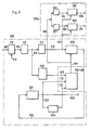
- FIG. 4 shows a runtime processing unit 100 which is capable of converting pulses of an electrical signal, for example, arriving via a line 101, into a sequence of run lengths, which emerge via a bus 102 and which appears as a sequence of numbers, each number of which is a run length expresses.
- the runlength processing unit 100 classifies the incoming impulses according to their runlengths with the aid of threshold values.
- the threshold values are stored in a threshold value memory 103 and can be made available to the runway processing unit 100 for processing the run lengths via a bus 104.
- the measured pulse lengths and classified with the threshold values are also fed via a bus 105 to a statistical evaluation unit 106.
- the threshold value memory 103 With the help of a statistic created therein about the frequency of the individual measured run lengths, it continuously adjusts the threshold values in the threshold value memory 103 in such a way that the threshold values for the greatest possible number of measured run lengths enable a clear classification. That's why a bus 107 is provided between the threshold value memory 103 and the evaluation unit 106.
- the output threshold values are also fed to the evaluation unit 106 via a bus 108.
- the current run length as well as the run length preceding the current run length and the subsequent run length are transmitted to the threshold value memory 103 via buses 109, 110, which allows threshold values for a measured run length to be output also as a function of the surrounding run lengths.
- the mode of operation of the device according to FIG. 4 can be better understood from the figures described below.
- FIG. 5 and FIG. 6 together show an exemplary embodiment of the device according to the invention according to FIG. 4. Those elements that already appear in FIG. 4 are provided with the same reference numerals.
- the threshold value generator 103 + 106 from FIG. 5 includes the threshold value memory 103 and the statistical evaluation unit 106 according to FIG. 4. This in turn consists of two parts 106a and 106b, one of which appears in FIG. 5 and the other in FIG. 6.
- These are simplified schematic representations in which, for example, no devices for the time control of the processes are shown. Such devices can, however, be created by the suitable specialist without effort on the basis of the information given below regarding the chronological sequence of these processes.
- Run lengths are distances between successive edges of a pulse in a signal. In this example, they can have values between "3" and “9", with a very fine gradation.
- the run lengths should be divided into classes or run length ranges by means of threshold values. In our case, such threshold values are the values "3, 4, 5, 6, 7, 8 and 9".
- the run lengths are named after the next smaller threshold. Thus at for example, run lengths in a class with values between "4" and "5" referred to as run length "4" etc.
- the signal to be processed arrives via line 101 in FIG. It consists of a sequence of pulses, as shown in FIG. 1a, which are separated by edges and merge into one another, as is known for digital signals. However, the signal to be processed can also appear converted into a signal according to one of FIGS. 1b or 1c.
- a counter 112 which receives a high-frequency clock signal according to FIG. 1d via a line 113, the length of the pulses between the edges is measured. This is called the impulse's length.
- the measured run length is fed via a bus 114 to a memory 115 or register, which stores it until a new run length is counted.
- the run lengths are now expressed by a number, which is forwarded in parallel with a 7-bit word, for example.
- a bus 116 connects the memory 115 to a further memory or register 117 and a run length generator 118, both of which are connected in parallel.
- the run length generator 118 which is designed as a ROM, for example, makes a first rough decision. This consists in having the value of LC Compare the values in the tables stored in it and LC assigns one of the run lengths "3, 4, 5, 6, 7, 8 or 9". All that is needed is a 3-bit word that is output to a bus 109.
- the run length LA which was first treated in this run length processing unit 100, is at this time on the bus 111 and is therefore applied to the threshold value generator 103 + 106.
- the running length LC is also created there, if only with an approximate value, in the bus 109. Now the length LB has to be determined. Since successive run lengths influence one another, several sequences of threshold values are stored in the threshold value generator 103 + 106. Each of these sequences is intended for a specific combination of the run lengths preceding and following the run length to be measured.
- the threshold value generator 103 + 106 can determine the suitable sequence of threshold values and, depending on the provisional value entered for LB (which is generated as described below), via bus 104 to the Submit comparator 120 where the barrel length LB has just been created.
- a hypothesis generator 121 Upstream of the threshold value generator 103 + 106 via the bus 110 is a hypothesis generator 121, which in turn is connected to the comparator 120 via a bus 122.
- the hypothesis generator 121 outputs preliminary values for the run length LB to be determined, which leads the threshold value generator 103 + 106 to output a corresponding threshold value to the comparator 120.
- the hypothesis generator 121 is designed, for example, as a sequencer which is activated by a newly arriving current run length and works on the principle of successive approximation. This means that he first outputs an average value for a run length, eg the value "6".
- the threshold value generator 103 + 106 outputs the "6" as a threshold value via the bus 104.
- the comparator 120 determines whether the measured value of the run length LB is larger or smaller than "6".
- the hypothesis generator 121 is informed of this finding via the bus 122 and makes a new choice. If the comparison has shown that, for example, the new threshold value is less than "6", the hypothesis generator 121 selects the "4" as the new preliminary run length. This in turn causes the threshold value generator 103 + 106 to output the "4" to the comparator 120 as a new threshold value. There, for example, it is found that LB is larger than "4". Thus the hypothesis generator 121 now selects the "5" as the last threshold value and the comparator 120 determines, for example, that LB is smaller.
- a first cycle which is used to determine a running length, has thus been completed.
- a second cycle follows in which the threshold values are better adapted to the run lengths measured so far.
- the threshold values are stored in the threshold value memory 103 (FIGS. 4, 6). This consists of a RAM memory 125 with values that are continuously adapted, as well as a ROM memory 126 with predefined values. Both are connected via a bus 127 and 128 to a switching element 129, which in turn leads into the bus 104.
- threshold values are output from the memory 126 via the bus 128 to the bus 104 and the bus 149.
- the threshold values from the bus 104 are used in a known manner, while the threshold values from the bus 149 are read into the memory 125 via the sequencer 147.
- the memory 125 has then filled and the switching element 129 goes into the position shown.
- the run lengths created via the buses 109, 110 and 111 reach the memories 125 and 126 via a bus 130, which enables the memories 125 and 126 to output the relevant threshold value via the bus 127 or 128.
- the second cycle begins during the first cycle by using the determined value of the run length LB now determined in order to have the threshold value generator 103 + 106 again read out the upper and lower threshold values for this run length via the bus 104. If the "4" was determined as the run length, then these are the threshold values "4" and "5". These two threshold values are fed to units 131 (FIG. 5) and 132 via a bus 108. In unit 132 the upper threshold is lowered by one (least significant) bit and in unit 131 the lower threshold is increased by one (least significant) bit. 3, run lengths 58 and 59 are thus determined.
- bus 133 and 134 These values are output via a bus 133 and 134 to a comparator 135 and 136, where they are compared with the current measured value of the running length LB, which is fed to the comparators 135 and 136 via a bus 105.
- a signal is emitted via the line 137 or 138 in question and fed to a sequencer 139 (FIG. 6).
- bus 110 has the current but already definitely determined running length LB at memory 141 as the address. This causes numbers stored there to be sent to the sequencer 139 via a bus 142.
- Such numbers indicate, for example, the difference in the number of previously measured run lengths 50 and 58 (FIG. 3) or 59 and 60.
- One of these numbers associated with the lower threshold is now incremented by one if there is a signal on line 137 and the other of these numbers associated with the upper threshold is decreased by one when a signal is on the line 138 is present. That means that for the formation of the named differences, the running lengths 58 and 60 positive, the running lengths 50 and 59 are counted negatively.
- Two such storage locations or a storage location in the memory 141 for each threshold value 55a, 55b are provided for each classified run length.
- the threshold value in question is unfavorable and must be shifted. If this process is completed or if there is a new value for a run length in the bus 110, the numbers from the sequencer 139 are returned to the memory 141 via a bus 140.
- the memory 141 is preferably designed as RAM. If there is another run length in the bus 110, corresponding processes run for other threshold values.
- the memory 141 together with the sequencer 139 counts how often run lengths occur with a given positive and negative deviation (or at a certain distance) from the valid threshold value. If the run lengths with positive or negative deviations predominate by a certain amount within a certain predetermined time, this threshold value must be shifted.
- a signal is transmitted to the sequencer 139 via a line 143, which indicates when and for how long the counting takes place.
- the sequencer 139 is informed via a line 144 when it can emit corresponding signals via lines 145 or 146 in order to shift a threshold value. In one line 145 the signal means that the threshold value is up and in the other line 146 that it is to be shifted down. This can be done in unit steps, for example.
- Lines 145 and 146 lead into a sequencer 147, which is connected via a bus 148 and 149 to memories 125 and 126, respectively.
- the bus 107 additionally connects the sequencer 147 to the memory 125.
- a corresponding threshold value can be exceeded the buses 127 and 148 arrive in the sequencer 147, where they are enlarged or reduced by a unit value and are then returned to the memory 125 via the bus 107.
- the threshold value is only changed if corresponding signals are present in lines 145 or 146.
- the operating state of the switching element 129 and the sequencer 147 can also be determined via a control line 150, which then cooperates with the memory 125 or with the memory 126 in accordance with the position of the switching element 129.
- the exemplary embodiment shown is intended in particular for the processing of digital audio signals. These occur at a frequency of at least 44 kHz. It is therefore conceivable to make certain simplifications for applications in connection with signals of lower frequencies.
- the method according to the invention is particularly suitable for processing digital signals which are coded according to a run length code and which have been changed during the transmission or recording, for example on a magnetic recording medium, in such a way that instead of the originally discrete run lengths, run lengths distributed over an area now occur.
- the aim of this processing is to be able to assign a discrete run length to these run lengths distributed over an area.
- the run lengths of the pulses that make up an input signal are measured.
- threshold values are also specified, which are intended to allow the totality of the run lengths occurring to be classified and to be assigned to some run length ranges or classes. All run lengths in the same class should originally have the same run length, ie before processing, transmission or recording of the input signal.
- the classes and thus the threshold values are determined with the help of a statistical evaluation of the measured runways gene determined. Then the threshold values and the measured run lengths are continuously coordinated so that the ongoing assignment of the run lengths to the classes is improved. This can be done by adapting the threshold values to the measured run lengths, as is done in the method just described. However, this can also be done in that the run lengths to be measured are previously better adapted to the specific threshold values, as is done using the method described below with FIGS. 7 to 11.
- FIG. 7 shows the already known run length processing unit 100, which is preceded by a pulse shaper 152.
- the latter receives the impulses of a signal arriving via a line 101a and changes them in a manner described later and outputs them via line 101 to the runtime processing unit 100.
- the pulses are processed in the manner already described. This is done using the threshold values that are stored in the memory 126.
- the processed run lengths exit via bus 102.
- the runtime processing unit 100 is connected to a statistical evaluation unit 106a + c via buses 105 and 110 and this in turn is connected via lines 145 and 146 to a correction signal generator 151. Lines 153 and 154 are provided for correction signals from the correction signal generator 151 to the pulse shaper 152.
- the run lengths of the pulses are processed in a first cycle and the correction signals for the pulses of the input signal are adapted in a second cycle.
- FIG. 8 shows a resonance amplifier 155 of the type that can be used, for example, as a pulse shaper 152. It consists in particular of an operational amplifier 156 with an output 157 and inputs 158 and 159. An input resistor 160 is connected upstream of the inverting input 158. The entrance 159 is connected to the earth. A feedback 161, which consists of an adjustable resistor 162, is provided on the inverting input 158 Capacity 163 and an adjustable inductor 164 in parallel. The inductance 164 is connected to a line 153 for the adjustment and the resistor to a line 154 for the same purpose. The output 157 is preferably connected to a comparator 185 so that a digital signal can be obtained.
- the structure and the mode of operation of the runlength processing unit 100 also corresponds in this case to that as described in accordance with FIG. 5.
- FIG. 9 shows the design of the threshold value generator 103 + 106 as it is designed for this case.
- the current run length LB is fed to the memory 126 via the bus 110.
- the preceding and the following run lengths are also fed to the memory 126 via further buses 109 and 111.
- This allows memory 126 to output a threshold value to comparator 120 via bus 104. This is repeated until the hypothesis generator 121 delivers a result.
- the last threshold value and the subsequent threshold value reduced by one, which is only of importance for the correction of the pulses, are fed in a known manner to the part 106a of the evaluation unit 106 and processed therein.
- the bus 137 and 138 accordingly emits signals to the sequencer 139, which together with the memory 141 forms part 106c.
- the sequencer 139 and the memory 141 together determine whether the threshold values are correct or unfavorable. If the threshold values are unfavorable, the sequencer 139 emits a signal via line 145, which means whether the threshold value is to be shifted up or down. A command is issued via line 146 as to whether and when the shift in the threshold value is desired. These signals are fed to a counter 165 and a counter 166. Both counters are also connected to the bus 110 and also receive a time signal via a line 167. For the sake of simplicity, only selected run lengths are observed for the assessment of the position of the threshold values.
- Counter 165 For example, only commands the shift of a threshold value from line 145 and 146 if a run length with the value "3" is present in bus 110.
- the counter 166 does the same for run lengths with the value "4".
- Both counters 165 and 166 count only as long as the time signal from line 167 permits this. Then this time signal starts the counter again.
- the count values from counters 165 and 166 are fed via lines 168 and 169 to an addition circuit 170 and added there.
- the result is entered via a line 171 into a memory 172 as the address.
- the memory 172 contains correction signals which are output to registers 175 and 176 via lines 173 and 174. These emit the correction signals whenever a counting period has ended.
- the correction signals can, for example, be determined experimentally beforehand and then read into the memory 172.
- the adjustable resistors 162 and inductances 164 of a resonance amplifier 155 can be adjusted with the correction signals which can be taken from the registers 175 and 176 via the lines 153 and 154. This changes the shape of the pulses in the input signal instead of the threshold values.
- FIG. 11 shows the frequency response of a resonance amplifier, for example the resonance amplifier 155.
- the frequency of a signal is plotted along the horizontal axis 180 and the amplification along the vertical axis 181.
- a curve 177 results with a maximum amplification for signals with a frequency f1.
- a signal consists of pulses of the same length, its frequency is constant and has the value f2, for example.
- a value for the amplification of this signal can be taken from curve 177.
- FIG. 8 Another possibility for the construction of a resonance amplifier is shown in FIG.
- the adjustable inductance 164 in the feedback coupling is replaced by a series connection of an adjustable resistor 182, a reversing amplifier 183 and an integrator 184.
- the output 157 also has a comparator 185.
- the resonance frequency can be changed by adjusting the two resistors 162 and 182.
- a digital signal is then available at the output 186 of the comparator 185.
- the Laplace transfer function A (p) also applies to the circuit according to FIG p is the Laplace operator and G are guide values.
Landscapes
- Physics & Mathematics (AREA)
- General Physics & Mathematics (AREA)
- Engineering & Computer Science (AREA)
- Signal Processing (AREA)
- Manipulation Of Pulses (AREA)
- Measurement Of Length, Angles, Or The Like Using Electric Or Magnetic Means (AREA)
- Compression, Expansion, Code Conversion, And Decoders (AREA)
Description
Die Erfindung betrifft ein Verfahren und eine Vorrichtung zur Verarbeitung von Impulsen eines Signales, das durch vorausgehende Uebertragung verzerrt ist, wobei Lauflaengen der einzelnen Impulse gemessen werden, mehrere Schwellwerte fuer die Lauflaengen vorgegeben werden, wobei die Schwellwerte Lauflaengenbereiche definieren, die Klassen fuer die gemessenen Lauflaengen bilden und die Klassen die urspruengliche Lauflaenge der unverzerrten Impulse angeben.The invention relates to a method and a device for processing pulses of a signal, which is distorted by previous transmission, wherein the run lengths of the individual pulses are measured, several threshold values for the run lengths are specified, the threshold values defining run length ranges, the classes for the measured run lengths form and the classes indicate the original length of the undistorted impulses.
Ein Verfahren und eine Vorrichtung aehnlicher Art ist aus "RADIO FERNSEHEN ELEKTRONIK" Band 32, Nr. 8, August 1983, Seiten 539 bis 54O, Ost-Berlin, bekannt. Die beschriebene Impuls- Zaehl- und Sortierschaltung ist in der Lage Impulse in einer Folge zu zaehlen und sie nach ihrer Dauer in vorher bestimmbare Klassen zu sortieren.A method and a device of a similar type are known from "RADIO TELEVISION ELECTRONICS"
Bei dieser Schaltung werden die Klassen einmal festgelegt und fuer immer so beibehalten. Eine Anpassung an die Art der Verzerrung die die eintreffenden Impulse erfahren haben, findet nachtraeglich nicht mehr statt. Damit sind ausserordentlich hohe Anforderungen bezueglich geschickter Definition der einzelnen Klassen gestellt, die schwer zu erfuellen sind.With this circuit, the classes are defined once and are retained forever. An adaptation to the type of distortion that the incoming impulses have experienced no longer takes place. This places extremely high demands on the skillful definition of the individual classes, which are difficult to meet.
Aus der europaeischen Patentanmeldung Nr 0 148 413 ist weiter ein Verfahren und eine Vorrichtung bekannt, mit der Fehler in Signalen, die in der Form von Impulsen beispielsweise mit einem magnetischen Aufzeichnungstraeger uebertragen werden, korrigiert werden koennen. Dabei werden insbesodere die Lauflaengen, die diese Impulse zwischen aufeinanderfolgenden Impulsflanken aufweisen korrigiert. Dazu werden zuerst Signalabweichungen zu den Lauflaengen ermittelt und gespeichert, dann wird eine direkte Verarbeitung der Eingangssignale zu Ausgangssignalen durchgefuehrt, indem Signalabweichungen mit den Eingangssignalen bzw. deren Lauflaengen kombiniert werden, so dass Ausgangssignale entstehen.From European patent application No. 0 148 413 a method and a device are known with which errors in signals which are transmitted in the form of pulses, for example with a magnetic recording medium, can be corrected. In particular, the run lengths that these pulses have between successive pulse edges are corrected. For this purpose, signal deviations from the run lengths are first determined and stored, then a direct processing of the input signals into output signals is carried out by Signal deviations are combined with the input signals or their run lengths, so that output signals arise.
Aus der europaeischen Patentanmeldung Nr 0 147 550 ist auch eine Schaltung zur Verarbeitung und insbesondere zur Umformung von Impulsen bekannt. Damit koennen verformte Impulse oder verzerrte Impulse so veraendert werden, dass sie der ihnen urspruenglich zugedachten Form, beispielsweise nach einer Aufzeichnung auf einem Magnetband, besser entsprechen. In dieser Schaltung wird der zeitliche Abstand je zweier aufeinanderfolgender Impulse, die die Daten darstellen, erfasst und gemessen. Dieser zeitliche Abstand gibt einen Hinweis auf die Groesse der Verzerrung der Impulse. Aufgrund dieser Messung wird ein Korrektursignal erzeugt, gemaess welchem die eintreffenden Impulse verformt werden.A circuit for processing and in particular for transforming pulses is also known from European patent application No. 0 147 550. In this way, deformed impulses or distorted impulses can be changed in such a way that they correspond better to the form originally intended for them, for example after recording on a magnetic tape. In this circuit, the time interval between two successive pulses representing the data is recorded and measured. This time interval gives an indication of the size of the distortion of the pulses. On the basis of this measurement, a correction signal is generated, according to which the incoming pulses are deformed.
Waehrend die Schaltung gemaess der Patentanmeldung Nr 0 148 413 zuerst vorbereitet werden muss, indem Speicher mit den Signalabweichungen aufgefuellt werden, kann die Schaltung gemaess Patentanmeldung Nr 0 147 550 ohne Vorbereitung sofort zum Einsatz gelangen, denn sie passt sich laufend an die eintreffenden Signale an.While the circuit according to patent application No. 0 148 413 must first be prepared by filling up memory with the signal deviations, the circuit according to patent application No. 0 147 550 can be used immediately without preparation, because it fits continuously to the incoming signals.
Der Nachteil der Schaltung gemaess der europaeischen Patentanmeldung 0 147 550 besteht darin, dass das analoge Eingangssignal auch auf analoge Art und Weise veraendert wird. Es wird damit versucht, das analoge Eingangssignal dem idealen und urspruenglichen analogen Signal anzupassen, was nur in dem Masse gelingen kann, als ein mehr oder weniger verstaerktes Korrektursignal dem Eingangssignal zugefuegt wird. Genuegt dies nicht, so sind die Moeglichkeiten dieser Schaltung ausgeschoepft.The disadvantage of the circuit according to European patent application 0 147 550 is that the analog input signal is also changed in an analog manner. An attempt is made to adapt the analog input signal to the ideal and original analog signal, which can only succeed to the extent that a more or less amplified correction signal is added to the input signal. If this is not enough, the possibilities of this circuit are exhausted.
Der Nachteil der Schaltung gemaess der europaeischen Patentanmeldung 0 148 413 besteht darin, dass die Korrektur der ermittelten Lauflaengen nicht adaptiv erfolgt, d.h. die Korrektur passt sich nicht laufend an die Signale an.The disadvantage of the circuit according to European patent application 0 148 413 is that the determined run lengths are not corrected adaptively, i.e. the correction does not continuously adapt to the signals.
Die Erfindung wie sie in den unabhängigen Anspruechen 1 und 8 gekennzeichnet ist, loest die Aufgabe ein Verfahren und eine Vorrichtung zu schaffen, mit denen die wirklichen oder urspruenglichen Lauflaengen der Impulse eines Signales adaptiv ermittelt werden koennen.The invention as characterized in
Die durch die Erfindung erreichten Vorteile sind insbesondere darin zu sehen, dass dadurch unmittelbar fuer die nachfolgende digitale Verarbeitung geeignete Signale erzeugt werden koennen. Es koennen demnach auch schnell arbeitende Bauelemente fuer die digitale Signalverarbeitung eingesetzt werden. Ferner kann sich die erfindungsgemaesse Vorrichtung selbsttaetig auf veraenderte Parameter einstellen. Die Information, die von einem Signal getragen wird, kann auch dann noch gelesen werden, wenn das Signal analog nicht vollstaendig entzerrt werden kann. Bei der Verarbeitung von Impulsen, die durch vorausgehende Aufzeichnung auf einem magnetischen Aufzeichnungstraeger verzerrt wurden, ist die erfindungsgemaesse Art der adaptiven Verarbeitung besonders vorteilhaft, weil die dabei verwendeten Aufnahme-und Wiedergabekoepfe nicht immer eine identische Charakteristik aufweisen. Ferner kann auch der verwendete Aufzeichnungstraeger abweichende Charakteristiken aufweisen. Ebenso kann die Bandgeschwindigkeit und der Aufnahmestrom variieren. Die Auswirkungen aller dieser unerwuenschten Abweichungen koennen durch die vorgeschlagene Verarbeitung ihre negative Wirkung nicht entfalten. Dies auch dann nicht, wenn diese Abweichungen sich langzeitlich aendern.The advantages achieved by the invention can be seen in particular in the fact that suitable signals can be generated directly for the subsequent digital processing. Accordingly, fast-working components can also be used for digital signal processing. Furthermore, the device according to the invention can adjust itself automatically to changed parameters. The information carried by a signal can still be read even if the signal cannot be completely equalized analog. When processing pulses which have been distorted by previous recording on a magnetic recording medium, the type of adaptive processing according to the invention is particularly advantageous because the recording and reproducing heads used do not always have an identical characteristic. Furthermore, the recording medium used also have different characteristics. The tape speed and the recording current can also vary. The effects of all of these undesired deviations cannot have their negative effect through the proposed processing. This does not apply even if these deviations change over time.
Im folgenden wird die Erfindung anhand von lediglich einen Ausfuehrungsweg darstellenden Zeichnungen naeher erlaeutert. Es zeigt:
Figur 1, a bis d verschiedene Formen digitaler Signale,Figur 2, a bis c Haeufigkeitsverteilungen und Schwellwerte fuer ein Signal,Figur 3 eine Besonderheit im Zusammenhang mit einer Haeufigkeitsverteilung,- Figur 4 ein Blockschema einer erfindungsgemaessen Vorrichtung,
Figuren 5 und 6 eine genauere Darstellung der Vorrichtung gemaess Figur 4,Figur 7 ein Blockschema einer weiteren Ausfuehrung der erfindungsgemaessen Vorrichtung,- Figuren 8, 9 und 10 je eine Ausfuehrung eines Teils der Vorrichtung gemaess
Figur 7 und Figur 11 eine Charakteristik fuer einen Teil gemaess Figur 8 und 10.
- 1, a to d different forms of digital signals,
- FIG. 2, a to c, frequency distributions and threshold values for a signal,
- FIG. 3 shows a special feature in connection with a frequency distribution,
- FIG. 4 shows a block diagram of a device according to the invention,
- FIGS. 5 and 6 show a more detailed illustration of the device according to FIG. 4,
- FIG. 7 shows a block diagram of a further embodiment of the device according to the invention,
- FIGS. 8, 9 and 10 each show an embodiment of part of the device according to FIGS. 7 and
- FIG. 11 shows a characteristic for a part according to FIGS. 8 and 10.
Figur 1a zeigt ein Signal 1, das aus einer Folge von positiven und negativen Impulsen 2, 3, 4, 5 und 6 zusammengesetzt ist. Diese Impulse 2 bis 6 werden durch Impulsflanken 7, 8, 9 und 10 untereinander abgegrenzt. Durchgangspunkte 11, 12, 13 und 14 dieser Impulsflanken 7 bis 10 durch eine Nulllinie 15 definieren Lauflaengen 16, 17 und 18 der Impulse 3, 4 und 5.Figure 1a shows a
Figur 1b zeigt das Signal 1a mit Impulsen 2a, 3a, 4a, 5a und 6a, die die Impulse 2 bis 6 des Signales 1 in idealer Form mit unendlich steilen Impulsflanken 7a bis 10a darstellen.Figure 1b shows the
Figur 1c zeigt ein Signal 19, das nur aus kurzen positiven Impulsen 20, 21, 22 und 23 besteht, die den Beginn einer neuen Lauflaenge anzeigen.Figure 1c shows a
Figur 1d zeigt ein Taktsignal 24, mit Impulsen 25, mit denen beispielsweise die Lauflaengen 16 bis 18 gemessen werden koennen.FIG. 1d shows a
Figur 2a zeigt eine Haeufigkeitsverteilung von gemessenen Lauflaengen. Auf der horizontalen Achse 26 sind Werte fuer die Lauflaengen aufgetragen. Auf der vertikalen Achse 27 sind Werte fuer die Haeufigkeit, mit der bestimmte Lauflaengen in einem Signal ueber laengere Zeit betrachtet auftreten, aufgetragen. Die Haeufigkeitsverteilung wird durch eine Linie 28 dargestellt. Vertikale Linien 29 bis 35 geben Schwellwerte fuer die Lauflaengen an. Man erkennt, dass die Haufigkeit von Lauflaengen im Beriche der Schwellwerte relativ gering, zwischen den Schwellwerten aber wesentlich hoeher ist. Gemessene Haeufigkeiten fuer einzelne Lauflaengen sind mit 36, 37 und 38 bezeichnet. Die Schwellwerte teilen das Gebiet der moeglichen Lauflaengen in Klassen oder Lauflaengenbereiche 61 bis 66 auf. Lauflaengen in einer Klasse weisen urspruenglich oder idealerweise dieselbe Lauflaenge auf.Figure 2a shows a frequency distribution of measured run lengths. Values for the running lengths are plotted on the
Figur 2b zeigt fuer die gemessenen Haeufigkeiten 36, 37 und 38 gemaess Figur 2a die entsprechenden Lauflaengen 39, 40 und 41.FIG. 2b shows the
Figur 2c zeigt wiederum eine horizontale Achse 45 mit Werten fuer Lauflaengen sowie eine vertikale Achse 46 mit Werten fuer die Haeufigkeit des Auftretens einzelner Lauflaengen in einem Signal. Die Haeufigkeitsverteilung ist durch eine Linie 47 dargestellt. Sie ist unter der Voraussetzung gemessen worden, dass die gemessenen Lauflaengen immer von einer vorausgehenden Lauflaenge mit dem gleichen Wert (oder Laenge) und von einer nachfolgenden Lauflaenge mit einem anderen aber immer gleichen Wert eingerahmt ist. Mit 51 ist die Lauflaenge bezeichnet, die zwischen den Schwellwerten 33 und 34 am haeufigsten auftritt. Mit 52 ist die Lauflaenge bezeichnet, die zwischen den Schwellwerten 34 und 35 am haeufigsten auftritt. Mit 53 ist ein neuer Schwellwert bezeichnet, der aus den haeufigsten Lauflaengen 51 und 52 abgeleitet ist. Er weist gleiche Abstaende 48 und 49 zu den haeufigsten Lauflaengen 51 und 52 auf. Im Vergleich zur Figur 2a erkennt man, dass fuer die Haeufigkeitsverteilung 47 wegen den veraenderten Randbedingungen, im Bereiche der Schwellwerte fast keine Lauflaengen gemessen werden.FIG. 2c again shows a
Figur 3 zeigt wiederum eine Haeufigkeitsverteilung, wie sie durch eine Kurve 54 dargestellt ist. Schwellwerte 55a und 55b sind dabei so bestimmt, dass davon ausgehend je ein positiver Abstand 56 und ein negativer Abstand 57 vorgesehen werden koennen, welche Lauflaengen 50, 58 und 59, 60 ergeben, die vorzugsweise mit je gleicher Haeufigkeit auftreten.FIG. 3 again shows a frequency distribution as represented by a
Figur 4 zeigt eine Lauflaengenverarbeitungseinheit 100, die in der Lage ist, ueber eine Leitung 101 eintreffende Impulse eines beispielsweise elektrischen Signales in eine Folge von Lauflaengen umzuwandeln, die ueber einen Bus 102 austreten und die als Folge von Zahlen erscheint, von denen jede Zahl eine Lauflaenge ausdrueckt. Die Lauflaengenverarbeitungseinheit 100 klassiert die eintreffenden Impulse gemaess ihren Lauflaengen mit Hilfe von Schwellwerten. Die Schwellwerte sind in einem Schwellwertspeicher 103 gespeichert und koennen ueber einen Bus 104 der Lauflaengenverarbeitungseinheit 100 fuer die Verarbeitung der Lauflaengen zur Verfuegung gestellt werden. Die gemessenen und mit den Schwellwerten klassierten Lauflaengen der Impulse werden zudem ueber einen Bus 105 einer Statistik-Auswertungseinheit 106 zugefuehrt. Mit Hilfe einer darin erstellten Statistik ueber die Haeufigkeit der einzelnen gemessenen Lauflaengen, passt diese laufend die Schwellwerte im Schwellwertspeicher 103 so an, dass die Schwellwerte fuer die groesstmoegliche Zahl der gemessenen Lauflaengen eine eindeutige Klassierung ermoeglichen. Deshalb ist ein Bus 107 zwischen dem Schwellwertspeicher 103 und der Auswertungseinheit 106 vorgesehen. Ueber einen Bus 108 werden die ausgegebenen Schwellwerte auch der Auswertungseinheit 106 zugefuehrt. Ueber Busse 109, 110 und 111 werden die aktuelle Lauflaenge wie auch die der aktuellen Lauflaenge vorausgehende Lauflaenge und die nachfolgende Lauflaenge dem Schwellwertspeicher 103 uebermittelt, was erlaubt, Schwellwerte fuer eine gemessene Lauflaenge auch in Funktion der umgebenden Lauflaengen auszugeben. Die Wirkungsweise der Vorrichtung gemaess Figur 4 kann anhand der nachfolgend beschriebenen Figuren besser verstanden werden.FIG. 4 shows a
Figur 5 und Figur 6 zeigen zusammen ein Ausfuehrungsbeispiel der erfindungsgemaessen Vorrichtung gemaess Figur 4. Dabei sind jene Elemente, die bereits in der Figur 4 erscheinen mit denselben Bezugszeichen versehen. Man beachte insbesondere, dass der Schwellwertgenerator 103 + 106 aus Figur 5, den Schwellwertspeicher 103 und die Statistik-Auswertungseinheit 106 gemaess Figur 4 umfasst. Diese wiederum besteht aus zwei Teilen 106a und 106b, von denen einer in der Figur 5 und der andere in der Figur 6 erscheint. Es handelt sich dabei um vereinfachte schematische Darstellungen, bei denen beispielsweise keine Vorrichtungen fuer die zeitliche Steuerung der Vorgaenge dargestellt sind. Solche Vorrichtungen koennen von dem geeigneten Fachmann aber ohne Muehe aufgrung der nachfolgend gemachten Angaben ueber den zeitlichen Ablauf dieser Vorgaenge erstellt werden.FIG. 5 and FIG. 6 together show an exemplary embodiment of the device according to the invention according to FIG. 4. Those elements that already appear in FIG. 4 are provided with the same reference numerals. It should be noted in particular that the
Zunaechst sei definiert, was in der nachfolgenden Beschreibung unter den Begriffen "Schwellwert" und "Lauflaenge" zu verstehen ist. Lauflaengen sind Abstaende zwischen aufeinanderfolgenden Flanken eines Impulses in einem Signal. Sie koennen in diesem Beispiel Werte zwischen "3" und "9" aufweisen und zwar mit sehr feiner Abstufung. Die Lauflaengen sollen durch Schwellwerte in Klassen oder Lauflaengenbereiche eingeteilt werden. Solche Schwellwerte sind in unserem Falle die Werte "3, 4, 5, 6, 7, 8 und 9". Die Lauflaengen sind nach dem naechst kleineren Schwellwert benannt. Somit werden bei spielsweise Lauflaengen in einer Klasse mit Werten zwischen "4" und "5" als Lauflaenge "4" bezeichnet usw. Dieser Uebereinkunft liegt die Annahme zugrunde, dass das Signal urspruenglich oder idealerweise nur Lauflaengen mit den Werten "3.5, 4.5, 5.5, 6.5, 7.5, 8.5 und 9.5" aufwies. Die um diese Werte streuenden Lauflaengen seien nun beispielsweise in erster Naeherung durch Schwellwerte "4, 5, 6, 7, 8 und 9" gegeneinander abgegrenzt und eben als Lauflaengen "3, 4, 5, 6, 7, 8 und 9" bezeichnet.First, what is to be understood in the following description under the terms "threshold value" and "running length". Run lengths are distances between successive edges of a pulse in a signal. In this example, they can have values between "3" and "9", with a very fine gradation. The run lengths should be divided into classes or run length ranges by means of threshold values. In our case, such threshold values are the values "3, 4, 5, 6, 7, 8 and 9". The run lengths are named after the next smaller threshold. Thus at for example, run lengths in a class with values between "4" and "5" referred to as run length "4" etc. This agreement is based on the assumption that the signal originally or ideally only run lengths with the values "3.5, 4.5, 5.5, 6.5, 7.5, 8.5 and 9.5 ". The running lengths scattering around these values are now delimited from one another, for example, by threshold values "4, 5, 6, 7, 8 and 9" and are referred to as running lengths "3, 4, 5, 6, 7, 8 and 9".
Ueber Leitung 101 in Figur 5 trifft das zu verarbeitende Signal ein. Es besteht aus einer Folge von Impulsen, wie sie in der Figur 1a gezeigt sind und die durch Flanken abgetrennt, ineinander uebergehen wie das fuer digitale Signale bekannt ist. Das zu verarbeitende Signal kann aber auch zu einem Signal gemaess einer der Figuren 1b oder 1c umgewandelt auftreten. In einem Zaehler 112, der ein hochfrequentes Taktsignal gemaess Figur 1d ueber eine Leitung 113 erhaelt, wird damit die Laenge der Impulse zwischen den Flanken gemessen. Diese wird als Lauflaenge des Impulses bezeichnet. Ueber einen Bus 114 wird die gemessene Lauflaenge einem Speicher 115 oder Register zugefuehrt, der diese solange speichert, bis eine neue Lauflaenge gezaehlt ist. Die Lauflaengen sind nun durch eine Zahl ausgedrueckt, welche beispielsweise mit einem 7-Bit-Wort parallel weitergeleitet wird. Ein Bus 116 verbindet den Speicher 115 mit einem weiteren Speicher oder Register 117 und einem Lauflaengengenerator 118, welche beide parellel geschaltet sind.The signal to be processed arrives via
Verfolgen wir nun, was mit drei aufeinanderfolgenden Lauflaengen LA, LB und LC geschieht. Von diesen tritt LC zuletzt auf und wird im Speicher 117 und im Lauflaengengenerator 118 eingelesen. Der Speicher 117 verzoegert jede Lauflaenge um die Zeit einer Lauflaenge. Wenn LC dort eintrifft, wird LB somit ausgelesen und ueber einen Bus 119 einem Vergleicher 120 zugefuehrt. Der Lauflaengengenerator 118, der beispielsweise als ROM ausgebildet ist, trifft eine erste grobe Entscheidung. Diese besteht darin, dass er den Wert von LC mit Werten der in ihm gespeicherten Tabellen vergleicht und LC eine der Lauflaengen "3, 4, 5, 6, 7, 8 oder 9" zuordnet. Dazu braucht es nur ein 3-Bit-Wort, das an einen Bus 109 abgegeben wird.Now let's see what happens to three consecutive runs LA, LB and LC. LC occurs last of these and is read into the
Die Lauflaenge LA, die zuerst in dieser Lauflaengenverarbeitungseinheit 100 behandelt wurde, befindet sich zu dieser Zeit im Bus 111 und ist somit an den Schwellwertgenerator 103+106 angelegt. Die Lauflaenge LC ist, wenn auch nur mit einem Naeherungswert, im Bus 109 ebenfalls dort angelegt. Zu bestimmen ist nun die Lauflaenge LB. Da aufeinanderfolgende Lauflaengen einander beeinflussen, sind im Schwellwertgenerator 103+106 mehrere Folgen von Schwellwerten gespeichert. Jede dieser Folgen ist fuer eine bestimmte Kombination von, der zu messenden Lauflaenge vorausgehenden und nachfolgenden Lauflaengen bestimmt. Da nun die vorausgehende Lauflaenge LA und die nachfolgende Lauflaenge LC bekannt sind, kann der Schwellwertgenerator 103+106 die geeignete Folge von Schwellwerten ermitteln und diese je nach dem eingegebenen vorlaeufigen Wert fuer LB (der wie nachfolgend beschrieben erzeugt wird) ueber den Bus 104 an den Vergleicher 120 abgeben, wo gerade die Lauflaenge LB angelegt ist.The run length LA, which was first treated in this run
Dem Schwellwertgenerator 103+106 ueber den Bus 110 vorgeschaltet, ist ein Hypothesengenerator 121, welcher wiederum ueber einen Bus 122 mit dem Vergleicher 120 verbunden ist. Der Hypothesengenerator 121 gibt ueber den Bus 110 angenommene vorlaeufige Werte fuer die zu bestimmende Lauflaenge LB ab, was den Schwellwertgenerator 103+106 jeweils dazu veranlasst, einen entsprechenden Schwellwert an den Vergleicher 120 abzugeben. Der Hypothesengenerator 121 ist beispielsweise als Sequenzer ausgebildet, der durch eine neueintreffende aktuelle Lauflaenge aktiviert wird und arbeitet nach dem Prinzip der sukzessiven Approximation. Das bedeutet, dass er zuerst einen mittleren Wert fuer eine Lauflaenge ausgibt, z.B. den Wert "6". Somit gibt der Schwellwertgenerator 103+106 als Schwellwert die "6" ueber den Bus 104 heraus. Der Vergleicher 120 stellt fest ob der gemessene Wert der Lauf laenge LB groesser oder kleiner als "6" ist. Diese Feststellung wird dem Hypothesengenerator 121 ueber den Bus 122 mitgeteilt und er trifft eine neue Wahl. Hat der Vergleich ergeben, dass z.B. der neue Schwellwert kleiner ist als "6", so waehlt der Hypothesengenerator 121 als neue vorlaeufige Lauflaenge die "4". Das veranlasst wiederum auf bekannte Weise den Schwellwertgenerator 103+106 als neuen Schwellwert die "4" an den Vergleicher 120 abzugeben. Dort wird beispielsweise festgestellt, dass LB groesser ist als "4". Somit waehlt nun der Hypothesengenerator 121 als letzten Schwellwert die "5" und der Vergleicher 120 stellt beispielsweise fest, dass LB kleiner ist. Dies wird wieder dem Hypothesengenerator 121 gemeldet und der schliesst nun aus dem Geschehen, dass die Lauflaenge LB einen Wert zwischen "4" und "5" hat und somit als "4" bezeichnet wird. Dieser wird einerseits ueber einen Bus 123 an ein Register 124 und andererseits ueber den Bus 102 als Resultat zur Weiterverarbeitung abgegeben. Das Register 124 verzoegert den Wert von LB um die Zeit einer Lauflaenge und gibt ihn dann an den Bus 111 ab. Dabei wird aus LB nun LA die aelteste Lauflaenge.Upstream of the
Ein erster Zyklus, der der Ermittlung einer Lauflaenge dient, ist somit abgeschlossen. Es folgt ein zweiter Zyklus, in dem die Schwellwerte an die bisher gemessenen Lauflaengen besser angepasst werden.A first cycle, which is used to determine a running length, has thus been completed. A second cycle follows in which the threshold values are better adapted to the run lengths measured so far.
Die Schwellwerte sind im Schwellwertspeicher 103 (Fig. 4, 6) gespeichert. Dieser besteht aus einem RAM-Speicher 125 mit Werten die laufend angepasst werden, sowie aus einem ROM-Speicher 126 mit fest vorgegebenen Werten. Beide sind ueber je einen Bus 127 und 128 mit einem Schaltelement 129 verbunden, das wiederum in den Bus 104 muendet. Wird die Vorrichtung in Betrieb genommen, so werden Schwellwerte aus dem Speicher 126 ueber den Bus 128 an den Bus 104 und den Bus 149 abgegeben. Die Schwellwerte aus dem Bus 104 werden in bekannter Weise verwendet, waehrend die Schwellwerte aus dem Bus 149 ueber den Sequenzer 147 in den Speicher 125 eingelesen werden. Nach einiger Zeit hat sich dann der Speicher 125 gefuellt und das Schaltelement 129 geht in die gezeigte Stellung ueber. Die ueber die Busse 109, 110 und 111 angelegten Lauflaengen erreichen die Speicher 125 und 126 ueber einen Bus 130, was jeweils die Speicher 125 und 126 befaehigt den betreffenden Schwellwert ueber den Bus 127 oder 128 auszugeben.The threshold values are stored in the threshold value memory 103 (FIGS. 4, 6). This consists of a
Der zweite Zyklus beginnt schon wahrend dem ersten Zyklus, indem der ermittelte Wert der nun bestimmten Lauflaenge LB dazu verwendet wird, um den Schwellwertgenerator 103+106 nochmals den oberen und unteren Schwellwert zu dieser Lauflaenge ueber den Bus 104 auslesen zu lassen. Wurde als Lauflaenge die "4" ermittelt, so sind dies die Schwellwerte "4" und "5". Ueber einen Bus 108 werden diese beiden Schwellwerte Einheiten 131 (Fig. 5) und 132 zugefuehrt. In der Einheit 132 wird der obere Schwellwert um ein (kleinstwertiges) Bit erniedrigt und in der Einheit 131 wird der untere Schwellwert um ein (kleinstwertiges) Bit erhoeht. In der Darstellung gemaess Figur 3, sind somit Lauflaengen 58 und 59 bestimmt. Diese Werte werden ueber je einen Bus 133 und 134 an je einen Vergleicher 135 und 136 abgegeben, wo sie mit dem aktuellen gemessenen Wert der Lauflaenge LB, die ueber einen Bus 105 den Vergleichern 135 und 136 zugefuehrt wird, verglichen werden. Immer dann wenn ein Wert (58, 59) in einem Bus 133 oder 134 mit LB aus dem Bus 105 uebereinstimmt, wird ein Signal ueber die betreffende Leitung 137 oder 138 abgegeben und einem Sequenzer 139 (Fig. 6) zugefuehrt. Zu dieser Zeit liegt im Bus 110 die aktuelle aber bereits definitiv ermittelte Lauflaenge LB am Speicher 141 als Adresse an. Dies bewirkt, dass dort gespeicherte Zahlen ueber einen Bus 142 an den Sequenzer 139 abgegeben wird. Solche Zahlen geben beispielsweise die Differenz der Anzahl bisher gemessener Lauflaengen 50 und 58 (Fig. 3) oder 59 und 60 an. Die eine dieser Zahlen, welche dem unteren Schwellwert zugeordnet ist, wird nun um Eins erhoeht, falls ein Signal in der Leitung 137 anliegt und die andere dieser Zahlen, die dem oberen Schwellwert zugeordnet ist, wird um Eins erniedrigt, wenn ein Signal in der Leitung 138 anliegt. Das bedeutet, dass fuer die Bildung genannter Differenzen, die Lauflaengen 58 und 60 positiv, die Lauflaengen 50 und 59 aber negativ gezaehlt werden. Fuer jede klassierte Lauflaenge sind zwei solcher Speicherplaetze oder fuer jeden Schwellwert 55a, 55b ein Speicherplatz im Speicher 141 vorgesehen. Sammeln sich in diesem Speicherplatz nach einer gewissen, ueber ein Signal in der Leitung 143 zugefuehrten, Zeit zu hohe Zaehlwerte, so liegt der betreffende Schwellwert unguenstig und muss verschoben werden. Ist dieser Vorgang abgeschlossen oder liegt ein neuer Wert fuer eine Lauflaenge im Bus 110 an, so werden die Zahlen aus dem Sequenzer 139 ueber einen Bus 140 wieder in den Speicher 141 zurueckgegeben. Der Speicher 141 ist vorzugsweise als RAM ausgebildet. Liegt im Bus 110 eine andere Lauflaenge an, so laufen entsprechende Vorgaenge fuer andere Schwellwerte ab.The second cycle begins during the first cycle by using the determined value of the run length LB now determined in order to have the
Mit anderen Worten zaehlt der Speicher 141 zusammen mit dem Sequenzer 139 wie haeufig Lauflaengen mit einer gegebenen positiven und negativen Abweichung (oder in einem bestimmten Abstand) vom gueltigen Schwellwert auftreten. Ueberwiegen die Lauflaengen mit positiven oder mit negativen Abweichungen innerhalb einer gewissen vorgegebenen Zeit um ein gewisses Mass, so muss dieser Schwellwert verschoben werden. Ueber eine Leitung 143 wird dem Sequenzer 139 ein Signal uebermittelt, das angibt, wann und wie lange gezaehlt wird. Ueber eine Leitung 144 wird dem Sequenzer 139 mitgeteilt wann er, um einen Schwellwert zu verschieben, entsprechende Signale ueber Leitungen 145 oder 146 abgeben kann. In der einen Leitung 145 bedeutet das Signal, dass der Schwellwert nach oben und in der anderen Leitung 146, dass er nach unten verschoben werden soll. Dies kann beispielsweise in Einheitsschritten erfolgen.In other words, the
Die Leitungen 145 und 146 muenden in einen Sequenzer 147, der ueber je einen Bus 148 und 149 mit den Speichern 125 und 126 verbunden ist. Der Bus 107 verbindet zusaetzlich den Sequenzer 147 mit dem Speicher 125. Immer wenn eine Lauflaenge LB im Bus 130 anliegt kann ein entsprechender Schwellwert ueber den Bus 127 und 148 in den Sequenzer 147 gelangen und dort um einen Einheitswert vergroessert oder verkleinert werden und anschliessend ueber den Bus 107 wieder in den Speicher 125 zurueckgegeben werden. Die Veraenderung des Schwellwertes findet aber nur dann statt, wenn in den Leitungen 145 oder 146 entsprechende Signale anliegen.
Ueber eine Steuerleitung 150 kann ferner der Betriebszustand des Schaltelementes 129 und des Sequenzers 147 bestimmt werden, der dann entsprechend der Stellung des Schaltelementes 129 mit dem Speicher 125 oder mit dem Speicher 126 zusammenarbeitet.The operating state of the
Das gezeigte Ausfuehrungsbeispiel ist insbesondere fuer die Verarbeitung von digitalen Audiosignalen vorgesehen. Diese fallen mit einer Frequenz von mindestens 44 kHz an. Es ist somit denkbar, fuer Anwendungen im Zusammenhang mit Signalen tieferer Frequenzen gewisse Vereinfachungen vorzunehmen.The exemplary embodiment shown is intended in particular for the processing of digital audio signals. These occur at a frequency of at least 44 kHz. It is therefore conceivable to make certain simplifications for applications in connection with signals of lower frequencies.
Das erfindungsgemaesse Verfahren eignet sich insbesondere zur Verarbeitung digitaler Signale, die gemaess einem Lauflaengencode codiert sind und welche waehrend der Uebertragung oder Aufzeichnung, beispielsweise auf einem magnetischen Aufzeichnungstraeger, so veraendert worden sind, dass statt den urspruenglich diskreten Lauflaengen nun ueber einen Bereich verteilte Lauflaengen auftreten. Ziel dieser Verarbeitung ist es, diesen ueber einen Bereich verteilten Lauflaengen wieder eine diskrete Lauflaenge zuordnen zu koennen. Dazu werden in einem ersten Schritt die Lauflaengen der Impulse, aus denen ein Eingangssignal besteht, gemessen. Parallel dazu werden auch Schwellwerte vorgegeben, die es gestatten sollen, die Gesamtheit der auftretenden Lauflaengen zu klassieren und einigen Lauflaengenbereichen oder Klassen zuzuordnen. Dabei sollen alle Lauflaengen in der gleichen Klasse urspruenglich, d.h. vor der Verarbeitung, Uebertragung oder Aufzeichnung des Eingangssignales, auch die gleiche Lauflaenge aufgewiesen haben. Die Klassen und somit die Schwellwerte werden mit Hilfe einer statistischen Auswertung der gemessenen Lauflaen gen ermittelt. Dann werden laufend auch die Schwellwerte und die gemessenen Lauflaengen so aufeinander abgestimmt, dass die laufende Zuordnung der Lauflaengen zu den Klassen verbessert wird. Dies kann dadurch geschehen, dass die Schwellwerte an die gemessenen Lauflaengen angepasst werden, wie dies in dem eben beschriebenen Verfahren geschieht. Dies kann aber auch dadurch geschehen, dass die zu messenden Lauflaengen vorgaengig an die bestimmten Schwellwerte besser angepasst werden, wie dies anhand des nachfolgend mit den Figuren 7 bis 11 beschriebenen Verfahrens geschieht.The method according to the invention is particularly suitable for processing digital signals which are coded according to a run length code and which have been changed during the transmission or recording, for example on a magnetic recording medium, in such a way that instead of the originally discrete run lengths, run lengths distributed over an area now occur. The aim of this processing is to be able to assign a discrete run length to these run lengths distributed over an area. In a first step, the run lengths of the pulses that make up an input signal are measured. At the same time, threshold values are also specified, which are intended to allow the totality of the run lengths occurring to be classified and to be assigned to some run length ranges or classes. All run lengths in the same class should originally have the same run length, ie before processing, transmission or recording of the input signal. The classes and thus the threshold values are determined with the help of a statistical evaluation of the measured runways gene determined. Then the threshold values and the measured run lengths are continuously coordinated so that the ongoing assignment of the run lengths to the classes is improved. This can be done by adapting the threshold values to the measured run lengths, as is done in the method just described. However, this can also be done in that the run lengths to be measured are previously better adapted to the specific threshold values, as is done using the method described below with FIGS. 7 to 11.
Figur 7 zeigt die bereits bekannte Lauflaengenverarbeitungseinheit 100, der ein Impulsformer 152 vorgeschaltet ist. Dieser erhaelt die ueber eine Leitung 101a eintreffenden Impulse eines Signales und veraendert sie in spaeter beschriebener Weise und gibt sie uber die Leitung 101 an die Lauflaengenverarbeitungseinheit 100 ab. Darin werden die Impulse auf die bereits beschriebene Weise verarbeitet. Dies geschieht mit Hilfe der Schwellwerte die im Speicher 126 gespeichert sind. Die verarbeiteten Lauflaengen treten ueber den Bus 102 aus. Ueber Busse 105 und 110 ist die Lauflaengenverarbeitungseinheit 100 an eine Statistik-Auswertungseinheit 106a+c und diese wiederum ist ueber Leitungen 145 und 146 an einen Korrektursignalgenerator 151 angeschlossen. Leitungen 153 und 154 sind fuer Korrektursignale aus dem Korrektursignalgenerator 151 an den Impulsformer 152 vorgesehen. Auch hier werden in einem ersten Zyklus die Lauflaengen der Impulse verarbeitet und in einem zweiten Zyklus werden die Korrektursignale fuer die Impulse des Eingangssignales angepasst.FIG. 7 shows the already known run
Figur 8 zeigt einen Resonanzverstaerker 155 wie er beispielsweise als Impulsformer 152 verwendet werden kann. Er besteht insbesondere aus einem Operationsverstaerker 156 mit einem Ausgang 157 und Eingaengen 158 und 159. Dem invertierenden Eingang 158 ist ein Eingangswiderstand 160 vorgeschaltet. Der Eingang 159 ist mit der Erde verbunden. Auf den invertierenden Eingang 158 ist eine Rueckkopplung 161 vorgesehen, die aus einem verstellbaren Widerstand 162, einer Kapazitaet 163 und einer verstellbaren Induktivitaet 164 in Paralellschaltung besteht. Die Induktivitaet 164 ist fuer die Verstellung an eine Leitung 153 und der Widerstand zum selben Zweck an eine Leitung 154 angeschlossen. Vorzugsweise ist der Ausgang 157 an einen Komparator 185 angeschlossen, so dass ein digitales Signal abgenommen werden kann.FIG. 8 shows a
Der Aufbau und die Funktionsweise der Lauflaengenverarbeitungseinheit 100 entspricht auch fuer diesen Fall demjenigen wie er gemaess Figur 5 beschrieben ist.The structure and the mode of operation of the
Figur 9 zeigt die Ausbildung des Schwellwertgenerators 103+106 wie er fuer diesen Fall ausgebildet ist. Ueber den Bus 110 wird die aktuelle Lauflaenge LB dem Speicher 126 zugefuehrt. Ueber weitere Busse 109 und 111 wird die vorausgehende und die nachfolgende Lauflaenge dem Speicher 126 ebenfalls zugefuehrt. Dies erlaubt dem Speicher 126 einen Schwellwert ueber den Bus 104 an den Vergleicher 120 abzugeben. Dies wiederholt sich so oft, bis der Hypothesengenerator 121 ein Resultat abgibt. Der letzte Schwellwert und der um Eins erniedrigte folgende Schwellwert, der nur fuer die Korrektur der Impulse eine Bedeutung hat, werden in bekannter Weise dem Teil 106a der Auswertungseinheit 106 zugefuehrt und darin verarbeitet. Der Bus 137 und 138 gibt dementsprechend Signale an den Sequenzer 139 ab, der zusammen mit dem Speicher 141 den Teil 106c bildet. In bekannter Weise wird im Sequenzer 139 und im Speicher 141 zusammen ermittelt, ob die Schwellwerte richtig oder unguenstig liegen. Falls die Schwellwerte unguenstig liegen, gibt der Sequenzer 139 ueber die Leitung 145 ein Signal ab, das bedeutet ob der Schwellwert nach oben oder nach unten zu verschieben ist. Ueber die Leitung 146 wird ein Befehl erteilt ob und wann die Verschiebung des Schwellwertes erwuenscht ist. Diese Signale werden einem Zaehler 165 und einem Zaehler 166 zugefuehrt. Beide Zaehler sind auch an den Bus 110 angeschlossen und erhalten zudem ueber eine Leitung 167 ein Zeitsignal. Fuer die Beurteilung der Lage der Schwellwerte werden einfachheitshalber nur ausgewaehlte Lauflaengen beobachtet. Deshalb zaehlt der Zaehler 165 beispielsweise nur dann die Befehle zur Verschiebung eines Schwellwertes aus der Leitung 145 und 146, wenn eine Lauflaenge mit dem Wert "3" im Bus 110 anliegt. Der Zaehler 166 tut dasselbe fuer Lauflaengen mit dem Wert "4". Beide Zaehler 165 und 166 zaehlen aber nur solange das Zeitsignal aus der Leitung 167 dies zulaesst. Dann startet dieses Zeitsignal die Zaehler wieder. Die Zaehlwerte aus den Zaehlern 165 und 166 werden ueber Leitungen 168 und 169 einer Additionsschaltung 170 zugefuehrt und dort addiert. Das Resultat wird ueber eine Leitung 171 einem Speicher 172 als Adresse eingegeben. Der Speicher 172 enthaelt Korrektursignale, die ueber Leitungen 173 und 174 an Register 175 und 176 abgegeben werden. Diese geben die Korrektursignale immer dann ab, wenn eine Zaehlperiode zu Ende ist. Die Korrektursignale koennen beispielsweise vorausgehend experimentell ermittelt und dann in den Speicher 172 eingelesen werden.FIG. 9 shows the design of the
Mit den Korrektursignalen, die ueber die Leitungen 153 und 154 aus den Registern 175 und 176 entnommen werden koennen, lassen sich die verstellbaren Widerstaende 162 und Induktivitaeten 164 eines Resonanzverstaerkers 155 verstellen. Damit wird die Form der Impulse im Eingangssignal anstatt der Schwellwerte veraendert.The
Figur 11 zeigt den Frequenzgang eines Resonanzverstaerkers, beispielsweise des Resonanzverstaerkers 155. Dabei ist laengs der horizontalen Achse 180 die Frequenz eines Signales und laengs der vertikalen Achse 181 die Verstaerkung aufgetragen. Je nach Einstellung des Widerstandes 162 und der Induktivitaet 164 ergibt sich eine Kurve 177 mit einer maximalen Verstaerkung fuer Signale mit einer Frequenz f1. Besteht ein Signal beispielsweise nur aus gleich langen Impulsen, so ist seine Frequenz konstant und hat beispielsweise den Wert f2. Dabei kann aus der Kurve 177 ein Wert fuer die Verstaerkung dieses Signales entnommen werden. Durch Veraendern der Verstaerkung fuer dieses Signal, kann die Form der Impulse und auch der Ort der Nulldurchgaenge der Flanken dieser Impulse veraendert werden. Dies ist beispielsweise erwuenscht, um die Signale und deren Lauflaengen besser an die vorhandenen Schwellwerte anzupassen. Um also die Verstaerkung bei einer bestimmten Frequenz zu veraendern, wird im Resonanzverstaerker der Widerstand und die Induktivitaet veraendert. Dies ergibt in der Figur 11 beispielsweise eine andere Kurve 178 mit maximaler Verstaerkung bei einer Frequenz f3. Fuer die Frequenz f2 ergibt sich eine um den Betrag 179 erhoehte Verstaerkung. Diese wird somit durch die Korrektursignale in den Leitungen 153 und 154 (Figur 9) bewirkt.FIG. 11 shows the frequency response of a resonance amplifier, for example the
Eine weitere Moeglichkeit fuer den Aufbau eines Resonanzverstaerkers ist in der Figur 10 gezeigt. Neben den bereits aus der Figur 8 bekannten Elementen, ist in der Ruekkopplung die verstellbare Induktivitaet 164 durch eine Serieschaltung eines verstellbaren Widerstandes 182, eines Umkehrverstaerkers 183 und eines Integrierers 184 ersetzt. Der Ausgang 157 weist auch noch einen Komparator 185 auf. Bei diesem Resonanzverstaerker kann die Resonanzfrequenz durch Verstellen der beiden Widerstaende 162 und 182 veraendert werden. Am Ausgang 186 des Komparators 185 ist dann ein digitales Signal erhaeltlich. Fuer die Schaltung gemaess Figur 10 gilt die Laplace-Uebertragungsfunktion A (p) mit
Claims (10)
Applications Claiming Priority (2)
| Application Number | Priority Date | Filing Date | Title |
|---|---|---|---|
| CH2772/86 | 1986-07-10 | ||
| CH277286 | 1986-07-10 |
Publications (2)
| Publication Number | Publication Date |
|---|---|
| EP0253215A1 EP0253215A1 (en) | 1988-01-20 |
| EP0253215B1 true EP0253215B1 (en) | 1991-01-02 |
Family
ID=4241263
Family Applications (1)
| Application Number | Title | Priority Date | Filing Date |
|---|---|---|---|
| EP87109510A Expired - Lifetime EP0253215B1 (en) | 1986-07-10 | 1987-07-02 | Method and apparatus for processing pulses of a signal which is distorted during transmission |
Country Status (3)
| Country | Link |
|---|---|
| US (1) | US4908771A (en) |
| EP (1) | EP0253215B1 (en) |
| DE (1) | DE3766902D1 (en) |
Families Citing this family (9)
| Publication number | Priority date | Publication date | Assignee | Title |
|---|---|---|---|---|
| FR2628273B1 (en) * | 1988-03-02 | 1994-08-12 | Saleeby Robert | PULSE TRAIN TRANSMITTER |
| FR2662808B1 (en) * | 1990-05-30 | 1992-08-21 | France Etat | METHOD FOR AUTOMATIC SIGNAL ANALYSIS BY SEGMENTATION AND CLASSIFICATION. |
| JPH0528063A (en) * | 1991-07-24 | 1993-02-05 | Nec Corp | Microcomputer |
| US5475312A (en) * | 1994-06-07 | 1995-12-12 | Iris Power Engineering Inc. | Method and device for distinguishing between partial discharge and electrical noise |
| AU2001263428A1 (en) * | 2001-01-09 | 2002-12-03 | Burstein Technologies, Inc. | Methods and apparatus for analyzing operational and nonoperational data acquired from optical discs |
| US7336705B2 (en) * | 2003-03-18 | 2008-02-26 | Microsoft Corporation | Smart receiver for wireless peripherals |
| US6995750B2 (en) * | 2003-03-19 | 2006-02-07 | Microsoft Corporation | RF data compression for a high speed mouse |
| US7158580B1 (en) * | 2003-04-17 | 2007-01-02 | Microsoft Corporation | Data pulse spectrum control |
| TWI241067B (en) * | 2004-06-02 | 2005-10-01 | Realtek Semiconductor Corp | Statistical circuit in an optical storage control chip |
Family Cites Families (11)
| Publication number | Priority date | Publication date | Assignee | Title |
|---|---|---|---|---|
| US3062442A (en) * | 1961-04-17 | 1962-11-06 | Space General Corp | Pulse detector apparatus |
| GB1425033A (en) * | 1972-03-10 | 1976-02-18 | Hendrickson A E | Data signal recogniion apparatus |
| US3790881A (en) * | 1973-03-06 | 1974-02-05 | Us Army | Pulse width selector |
| US3936740A (en) * | 1974-02-13 | 1976-02-03 | Coulter Electronics, Inc. | Method and apparatus for automatically sampling pulses a predetermined average number of times for storage and subsequent reproduction |
| US3956616A (en) * | 1974-05-06 | 1976-05-11 | Knollenberg Robert G | Method and apparatus for generating a statistical basis |
| US3961271A (en) * | 1975-02-07 | 1976-06-01 | International Telephone And Telegraph Corporation | Pulse width and amplitude screening circuit |
| US4162453A (en) * | 1977-07-27 | 1979-07-24 | United States Steel Corporation | Duration range determination of incursions by a variable signal |
| SU869011A1 (en) * | 1980-01-03 | 1981-09-30 | Предприятие П/Я В-2965 | Pulse signal classifier |
| DE3140432C2 (en) * | 1980-10-13 | 1985-10-10 | Hitachi, Ltd., Tokio/Tokyo | Speed control circuit |
| US4562549A (en) * | 1981-10-14 | 1985-12-31 | Hitachi, Ltd. | Digital player using a pulse width detector |
| CU21488A1 (en) * | 1982-07-26 | 1987-06-09 | Inst Central De Investigacion | Logic measurement |
-
1987
- 1987-07-02 EP EP87109510A patent/EP0253215B1/en not_active Expired - Lifetime
- 1987-07-02 DE DE8787109510T patent/DE3766902D1/en not_active Expired - Lifetime
- 1987-07-06 US US07/070,846 patent/US4908771A/en not_active Expired - Fee Related
Also Published As
| Publication number | Publication date |
|---|---|
| EP0253215A1 (en) | 1988-01-20 |
| US4908771A (en) | 1990-03-13 |
| DE3766902D1 (en) | 1991-02-07 |
Similar Documents
| Publication | Publication Date | Title |
|---|---|---|
| EP0517324B1 (en) | Apparatus for controlling the quantifier of a hybrid coder | |
| EP0253215B1 (en) | Method and apparatus for processing pulses of a signal which is distorted during transmission | |
| DE68909374T2 (en) | Method and device for restoring a data signal. | |
| DE69310946T2 (en) | Method and means for detecting a routing loop in a telecommunications network | |
| DE19703965C1 (en) | Process for transforming a fuzzy logic used to simulate a technical process into a neural network | |
| DE3247778A1 (en) | ARRANGEMENT FOR CONTROLLING THE AMPLIFICATION OF DIGITALIZED SIGNALS | |
| EP0845921A1 (en) | Method and circuit for regulating the volume in digital hearing aids | |
| EP0449370B1 (en) | Circuit arrangement for steepening signal edges | |
| EP0813986B1 (en) | Method for distance control in a vehicle | |
| EP0027233A1 (en) | Coding method for analog signals | |
| EP0889655B1 (en) | Digital data encoder and method for encoding data | |
| EP0905954A2 (en) | Telephone answering machine and method for recording a digital audio signal | |
| DE19624614C2 (en) | Process for designing or adapting a fuzzy controller or a system of linked fuzzy controllers | |
| EP3396919A1 (en) | Method for transferring data from one device to a data processing means, transmission unit, device and system | |
| DE836045C (en) | System for the transmission of electrical signals with recurring fixed level or reference values | |
| DE3240175A1 (en) | ADAPTIVE ANALOG / DIGITAL CONVERTER SYSTEM | |
| EP0512365A1 (en) | Apparatus for aurally compensated volume regulation | |
| EP0406741B1 (en) | Quasi-synchronous decision method for channel changing | |
| EP1751871B1 (en) | Method and device for the automatic definition of value range limits that are associated with code words for sampling values | |
| DE1287114B (en) | Method and arrangement for reducing statistical disturbances in a television picture | |
| DE3443616C2 (en) | ||
| WO1990009711A1 (en) | A device for shortening a distributed queue | |
| DE2619712A1 (en) | CIRCUIT ARRANGEMENT FOR AUTOMATIC ADJUSTMENT OF A TWO WIRE FULL DUPLEX DATA TRANSFER SYSTEM | |
| EP0384920B1 (en) | Circuit for digitally adjusting the gain of a digitally adjustable receiver amplifier | |
| DE69021951T2 (en) | Method for generating a masking bit during a dynamic comparison of a serial data stream with a reference. |
Legal Events
| Date | Code | Title | Description |
|---|---|---|---|
| PUAI | Public reference made under article 153(3) epc to a published international application that has entered the european phase |
Free format text: ORIGINAL CODE: 0009012 |
|
| AK | Designated contracting states |
Kind code of ref document: A1 Designated state(s): CH DE FR GB IT LI |
|
| 17P | Request for examination filed |
Effective date: 19880707 |
|
| 17Q | First examination report despatched |
Effective date: 19891116 |
|
| GRAA | (expected) grant |
Free format text: ORIGINAL CODE: 0009210 |
|
| AK | Designated contracting states |
Kind code of ref document: B1 Designated state(s): CH DE FR GB IT LI |
|
| ITF | It: translation for a ep patent filed | ||
| REF | Corresponds to: |
Ref document number: 3766902 Country of ref document: DE Date of ref document: 19910207 |
|
| ET | Fr: translation filed | ||
| GBT | Gb: translation of ep patent filed (gb section 77(6)(a)/1977) | ||
| PG25 | Lapsed in a contracting state [announced via postgrant information from national office to epo] |
Ref country code: GB Effective date: 19910702 |
|
| PG25 | Lapsed in a contracting state [announced via postgrant information from national office to epo] |
Ref country code: DE Effective date: 19910705 |
|
| PG25 | Lapsed in a contracting state [announced via postgrant information from national office to epo] |
Ref country code: LI Effective date: 19910731 Ref country code: CH Effective date: 19910731 |
|
| RAP2 | Party data changed (patent owner data changed or rights of a patent transferred) |
Owner name: STUDER REVOX AG |
|
| PLBE | No opposition filed within time limit |
Free format text: ORIGINAL CODE: 0009261 |
|
| STAA | Information on the status of an ep patent application or granted ep patent |
Free format text: STATUS: NO OPPOSITION FILED WITHIN TIME LIMIT |
|
| 26N | No opposition filed | ||
| GBPC | Gb: european patent ceased through non-payment of renewal fee | ||
| PG25 | Lapsed in a contracting state [announced via postgrant information from national office to epo] |
Ref country code: FR Effective date: 19920331 |
|
| REG | Reference to a national code |
Ref country code: CH Ref legal event code: PL |
|
| REG | Reference to a national code |
Ref country code: FR Ref legal event code: ST |
|
| PG25 | Lapsed in a contracting state [announced via postgrant information from national office to epo] |
Ref country code: IT Free format text: LAPSE BECAUSE OF NON-PAYMENT OF DUE FEES;WARNING: LAPSES OF ITALIAN PATENTS WITH EFFECTIVE DATE BEFORE 2007 MAY HAVE OCCURRED AT ANY TIME BEFORE 2007. THE CORRECT EFFECTIVE DATE MAY BE DIFFERENT FROM THE ONE RECORDED. Effective date: 20050702 |