EP0252681B1 - Improvements to a product display and dispensing unit - Google Patents
Improvements to a product display and dispensing unit Download PDFInfo
- Publication number
- EP0252681B1 EP0252681B1 EP87305842A EP87305842A EP0252681B1 EP 0252681 B1 EP0252681 B1 EP 0252681B1 EP 87305842 A EP87305842 A EP 87305842A EP 87305842 A EP87305842 A EP 87305842A EP 0252681 B1 EP0252681 B1 EP 0252681B1
- Authority
- EP
- European Patent Office
- Prior art keywords
- compartment
- lid
- dispensing unit
- compartments
- product display
- Prior art date
- Legal status (The legal status is an assumption and is not a legal conclusion. Google has not performed a legal analysis and makes no representation as to the accuracy of the status listed.)
- Expired - Lifetime
Links
- 230000000295 complement effect Effects 0.000 claims abstract description 10
- 239000000463 material Substances 0.000 claims description 11
- 238000004140 cleaning Methods 0.000 claims description 3
- 239000004033 plastic Substances 0.000 claims description 3
- 229920003023 plastic Polymers 0.000 claims description 3
- 230000013011 mating Effects 0.000 claims 1
- 230000000063 preceeding effect Effects 0.000 claims 1
- 235000013305 food Nutrition 0.000 description 6
- 229920002972 Acrylic fiber Polymers 0.000 description 4
- NIXOWILDQLNWCW-UHFFFAOYSA-N acrylic acid group Chemical group C(C=C)(=O)O NIXOWILDQLNWCW-UHFFFAOYSA-N 0.000 description 2
- 235000009508 confectionery Nutrition 0.000 description 2
- 238000011109 contamination Methods 0.000 description 2
- 235000011869 dried fruits Nutrition 0.000 description 1
- 230000009977 dual effect Effects 0.000 description 1
- 235000013402 health food Nutrition 0.000 description 1
- 235000014571 nuts Nutrition 0.000 description 1
- 239000004417 polycarbonate Substances 0.000 description 1
- 229920000515 polycarbonate Polymers 0.000 description 1
- 239000004800 polyvinyl chloride Substances 0.000 description 1
- 229920000915 polyvinyl chloride Polymers 0.000 description 1
- 235000010604 prepared salads Nutrition 0.000 description 1
- 230000000717 retained effect Effects 0.000 description 1
- 238000007789 sealing Methods 0.000 description 1
- 210000002105 tongue Anatomy 0.000 description 1
- 239000002699 waste material Substances 0.000 description 1
Images




Classifications
-
- A—HUMAN NECESSITIES
- A47—FURNITURE; DOMESTIC ARTICLES OR APPLIANCES; COFFEE MILLS; SPICE MILLS; SUCTION CLEANERS IN GENERAL
- A47F—SPECIAL FURNITURE, FITTINGS, OR ACCESSORIES FOR SHOPS, STOREHOUSES, BARS, RESTAURANTS OR THE LIKE; PAYING COUNTERS
- A47F5/00—Show stands, hangers, or shelves characterised by their constructional features
- A47F5/0018—Display racks with shelves or receptables
- A47F5/0025—Display racks with shelves or receptables having separate display containers or trays on shelves or on racks
-
- A—HUMAN NECESSITIES
- A47—FURNITURE; DOMESTIC ARTICLES OR APPLIANCES; COFFEE MILLS; SPICE MILLS; SUCTION CLEANERS IN GENERAL
- A47F—SPECIAL FURNITURE, FITTINGS, OR ACCESSORIES FOR SHOPS, STOREHOUSES, BARS, RESTAURANTS OR THE LIKE; PAYING COUNTERS
- A47F5/00—Show stands, hangers, or shelves characterised by their constructional features
- A47F5/0018—Display racks with shelves or receptables
Definitions
- the present invention relates to improvements to product display and dispensing units.
- Display and dispensing units In retail outlets it is customary to have display and dispensing units for use in selling loose confectionery, dried fruit and nuts and various food products on a self service basis. Each unit has a number of compartments each containing a different variety of confectionery or food. The customer selects the required amount from each compartment, using a scoop or other handling device. Display and dispensing units may also be termed as merchandising units.
- the prior art units are manufactured from sheets of a plastics material such as acrylic which are glued together to form the structure. Each compartment is provided with a hinged lid.
- each compartment be cleaned regularly. As the compartments are glued together, however, it is not possible to clean them thoroughly, particularly the corners. Also, the hinge of the lid may corrode after a short period of time and thus provides a possible source of contamination.
- a second major disadvantage associated with prior art units is that as each unit may have four or six individual compartments, if one compartment is damaged or broken, then it is usually necessary to discard the entire unit.
- a further disadvantage associated with prior art units is the waste of material. As each unit is normally two compartments wide, a plurality of units located side by side will have a number of juxtaposed side walls.
- French Patent Specification No. 2064531 discloses a storage bin comprising a frame formed as a front, base and rear and two side panels.
- the frame and side panels are provided with matching locking components which enable these elements to be interconnected.
- the flexible frame is retained in its bin shape upon assembly with the rigid side panels.
- US-A-2368909 discloses a merchandise display stand having a pair of side members supporting a tiered merchandise shelving arrangement.
- the shelving is provided with tongues for engagement with lips provided on the inner surfaces of the side members.
- the object of the invention is to alleviate the above disadvantages of the prior art units.
- the present invention provides a product display and dispensing unit comprising a pair of side panels and at least one compartment for loose products arranged between the side panels, each compartment including a body member, and pairs of complementary engageable and disengageable means for connecting the body member to the side panels, each of the pairs of complementary engageable and disengageable means comprising a key having an open ended notch and a complementary slot in a side panel, and each body member having a plurality of said keys, characterised in that at least two compartments are juxtaposed and the corresponding keys of the body members of any two juxtaposed compartments are engageable in a single slot in a common side panel located between the juxtaposed compartments.
- At least one of the juxtaposed compartments comprises one of a column of compartments and each compartment of the or each column is arranged between a single pair of side panels.
- the body member is formed from a sheet of plastics material of uniform thickness.
- each compartment is provided with a lid which is freely supported at one end, whereby the lid may be pivoted about that end and moved into the body of the compartment to allow access thereto or may be removed for cleaning purposes.
- each compartment is provided with a lid which is pivotally and removably attached to the body with closing means being provided for gradually closing the lid whereby when the lid is opened to allow access to the compartment the lid closes gradually so as to cover the product contained within the compartment.
- the invention also provides a product display and dispensing unit in which each compartment is provided with a filling and stacking chute by means of which the compartment may be stocked with product.
- a gasket seal is provided between the edges of the body member and the side panels.
- a seal may also be provided between the edges of the lid and the side panels.
- each display and dispensing unit comprises a plurality of juxtaposed compartments 10 each of which comprises a body member 12, a portion of side panels 14 and an unhinged lid 16.
- Each body member 12 is formed from a sheet of transparent acrylic plastics material and comprises a front lip 20, a base 21, a sloped and vertical rear wall 22 and a roof member 23.
- a pair of keys 25 is provided on the front lip 20 and the rear wall 22.
- Each of the keys 25 engages a complementary slot 26 in the side panels 14 which provides side walls for the compartments 10 and the unit as a whole.
- Each slot 26 accommodates two keys 25, one key of a compartment 10 located at either side of a panel 14.
- the lid 16 comprises a plate member 30 having an upper lip 31 and a handle 32. As best shown in Figure 2 the upper lid 31 engages with dowels 35 in the side panels 14. The lid 16 may be pivoted about the dowels 35 until it is in a horizontal position when it is pushed into the compartment 10 underneath the roof 23 until the handle 32 contacts the front edge of the roof member 23.
- the units of the invention may be arranged in any desired number of compartments high and wide to suit the space available and range of products on sale. This arrangement may be achieved by selecting the appropriate size panels 14.
- the units may be readily disassembled by disengaging the keys 25 from the slots 26 and readily reassembled when required.
- One compartment 410 of a unit is shown and it also comprises a body member 412, a side panel 414 and a lid 416. Keys 425 are provided on the body members 412 and engage complementary slots 426 in the side panels 414.
- the main additional feature associated with the second embodiment is the provision of a filling and stacking chute 417 which is accessed by removing cover 418.
- the filling of the chute 417 with product achieves two main functions. Firstly, as product is removed, the product in the chute 417 gravitates downwards thus replacing the product. Secondly, as the walls of the chute 417 are manufactured from a clear acrylic plastics material, the chute 417 provides a very effective display of the product being sold.
- a unit comprising these compartments 510 would be placed at a lower level than the units of the first and second embodiments.
- the display and dispensing compartments 510 function as dip bins and each unit comprises a body member 512 and side panels 514. No lid is provided and thus these compartments would be used for merchandise which is wrapped.
- Each body member 512 is formed from a sheet of transparent acrylic plastics material and comprises a front wall 520, a short base 521, an inner wall 522, a main base 523 and a rear wall 524.
- the space between the front wall 520 and the inner wall 522 is chiefly for display of the product being sold.
- the main dispensing region of the compartment is that region defined between the front wall 520, the main base 523 and the rear wall 524.
- the body member 512 is provided with three sets of keys 525 which engage in slots 526 on the side panels 514 as in the first embodiment.
- FIG. 7 to 9 illustrate the fourth embodiment.
- a unit of this embodiment comprises a number of compartments 710 which differ from the compartments 10 of the units of the first embodiment in that a gasket or sealing element 711 is provided between the body member 712 and engaged side panels 714.
- Each body member 712 is formed from a sheet of transparent acrylic plastics material and comprises a front lip 720, a base 721, a sloped and vertical rear wall 722 and a roof 723.
- a gasket 711 which in the fourth embodiment is a dual rigid/soft extruded polyvinylchloride material.
- the rigid part 711a of the gasket 711 is fitted over the edge of the body member 712 and the soft part 711b seals against the side panel 714.
- a pair of cranked keys 725 are attached to the front lip 720 and the rear wall 722.
- the keys 725 which are of a polycarbonate or a high impact acrylic material, are cranked to allow for the gasket 711 and are attached to the body member 712 by being surface glued and fillet welded.
- a unit of the fourth embodiment can be used to accommodate fine grain material, such as various health foods.
- the fifth embodiment of the invention is described with reference to Figures 10 and 11 of the drawings.
- the unit shown is mounted in a freezer display cabinet A and has three compartments 910. Trays 911 containing prepared food are contained within each compartment 910 and the food is removed by retail customers as required on a self-service basis.
- Each compartment 910 comprises a body member 912, the body member being supported by side panels 914. Keys 925 are provided on the body members 912 and engage complementary slots 926 in its side panels 914. A base 915 is provided in the cabinet A to support the side panels 914.
- Each of the compartments 910 has a lid 916 which is provided with a handle 917 and two arced lugs 918. The lugs 918 engage rubber grommets 919 which allow gradual closing of the lid 916 under its own weight when it has been opened. To remove a lid 916 the lugs 918 are merely removed from the grommets 919.
- An end panel 931 is located adjacent the upper edge of the uppermost lid 916 so as to prevent the lugs 918 from being accidentally removed from the grommets 919 when the lid is being opened.
Landscapes
- Vending Machines For Individual Products (AREA)
- Control Of Vending Devices And Auxiliary Devices For Vending Devices (AREA)
- Cartons (AREA)
- Display Racks (AREA)
- Packaging Of Annular Or Rod-Shaped Articles, Wearing Apparel, Cassettes, Or The Like (AREA)
- Stackable Containers (AREA)
- Packages (AREA)
Abstract
Description
- The present invention relates to improvements to product display and dispensing units.
- In retail outlets it is customary to have display and dispensing units for use in selling loose confectionery, dried fruit and nuts and various food products on a self service basis. Each unit has a number of compartments each containing a different variety of confectionery or food. The customer selects the required amount from each compartment, using a scoop or other handling device. Display and dispensing units may also be termed as merchandising units.
- The prior art units are manufactured from sheets of a plastics material such as acrylic which are glued together to form the structure. Each compartment is provided with a hinged lid.
- There are, however, a number of disadvantages associated with prior art units.
- Firstly, as the vast majority of products sold using these units are unwrapped, it is essential that each compartment be cleaned regularly. As the compartments are glued together, however, it is not possible to clean them thoroughly, particularly the corners. Also, the hinge of the lid may corrode after a short period of time and thus provides a possible source of contamination.
- A second major disadvantage associated with prior art units is that as each unit may have four or six individual compartments, if one compartment is damaged or broken, then it is usually necessary to discard the entire unit.
- Thirdly, when the units are being transported or stored, they use a considerable amount of space, thus adding to transport, storage and handling costs.
- A further disadvantage associated with prior art units is the waste of material. As each unit is normally two compartments wide, a plurality of units located side by side will have a number of juxtaposed side walls.
- Another problem encountered in retail outlets occurs with the sale on a self-service basis of prepared salads and other foods ready for consumption in that these foods are open to contamination.
- French Patent Specification No. 2064531 discloses a storage bin comprising a frame formed as a front, base and rear and two side panels. The frame and side panels are provided with matching locking components which enable these elements to be interconnected. The flexible frame is retained in its bin shape upon assembly with the rigid side panels.
- US-A-2368909 discloses a merchandise display stand having a pair of side members supporting a tiered merchandise shelving arrangement. The shelving is provided with tongues for engagement with lips provided on the inner surfaces of the side members.
- The object of the invention is to alleviate the above disadvantages of the prior art units.
- The present invention provides a product display and dispensing unit comprising a pair of side panels and at least one compartment for loose products arranged between the side panels, each compartment including a body member, and pairs of complementary engageable and disengageable means for connecting the body member to the side panels, each of the pairs of complementary engageable and disengageable means comprising a key having an open ended notch and a complementary slot in a side panel, and each body member having a plurality of said keys, characterised in that at least two compartments are juxtaposed and the corresponding keys of the body members of any two juxtaposed compartments are engageable in a single slot in a common side panel located between the juxtaposed compartments.
- Advantageously, at least one of the juxtaposed compartments comprises one of a column of compartments and each compartment of the or each column is arranged between a single pair of side panels.
- Preferably, the body member is formed from a sheet of plastics material of uniform thickness.
- According to one aspect of the invention, each compartment is provided with a lid which is freely supported at one end, whereby the lid may be pivoted about that end and moved into the body of the compartment to allow access thereto or may be removed for cleaning purposes.
- According to a further aspect of the invention, each compartment is provided with a lid which is pivotally and removably attached to the body with closing means being provided for gradually closing the lid whereby when the lid is opened to allow access to the compartment the lid closes gradually so as to cover the product contained within the compartment.
- The invention also provides a product display and dispensing unit in which each compartment is provided with a filling and stacking chute by means of which the compartment may be stocked with product.
- Also if desired, a gasket seal is provided between the edges of the body member and the side panels. A seal may also be provided between the edges of the lid and the side panels.
- The invention will hereinafter be more particularly described with reference to the accompanying drawings, which show by way of example only, five embodiments according to the invention. In the drawings:
- Figure 1 is a perspective view of a first embodiment of a unit according to the invention. The unit contains four compartments, two columns of two.
- Figure 2 is a cross-sectional side view of the unit as shown in Figure 1; and
- Figure 3 is an exploded perspective view of two of the compartments of the first embodiment;
- Figure 4 is a cross-sectional side view of one compartment of a second embodiment according to the invention;
- Figure 5 is a perspective view of two compartments of a third embodiment according to the invention;
- Figure 6 is an exploded view of one of the compartments of the third embodiment;
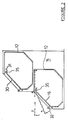
- Figure 7 is a cross sectional plan view of a compartment of a fourth embodiment according to the invention and having a body member and two side panels;
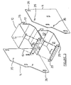
- Figure 8 is a perspective view of the body member of the fourth embodiment;
- Figure 9 is a detail view on a larger scale showing the connection between the body member and a side panel of the fourth embodiment;
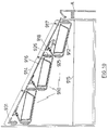
- Figure 10 is a cross-sectional side view of a unit of a fifth embodiment according to the invention and showing three compartments in side view; and
- Figure 11 is a cross-sectional side view of one compartment of the fifth embodiment on a larger scale.
- Referring to the drawings, and initially to Figures 1 to 3, each display and dispensing unit comprises a plurality of juxtaposed
compartments 10 each of which comprises abody member 12, a portion ofside panels 14 and anunhinged lid 16. - Each
body member 12 is formed from a sheet of transparent acrylic plastics material and comprises afront lip 20, abase 21, a sloped and verticalrear wall 22 and aroof member 23. A pair ofkeys 25 is provided on thefront lip 20 and therear wall 22. - Each of the
keys 25 engages acomplementary slot 26 in theside panels 14 which provides side walls for thecompartments 10 and the unit as a whole. Eachslot 26 accommodates twokeys 25, one key of acompartment 10 located at either side of apanel 14. - The
lid 16 comprises aplate member 30 having anupper lip 31 and ahandle 32. As best shown in Figure 2 theupper lid 31 engages withdowels 35 in theside panels 14. Thelid 16 may be pivoted about thedowels 35 until it is in a horizontal position when it is pushed into thecompartment 10 underneath theroof 23 until thehandle 32 contacts the front edge of theroof member 23. - The units of the invention may be arranged in any desired number of compartments high and wide to suit the space available and range of products on sale. This arrangement may be achieved by selecting the
appropriate size panels 14. - For cleaning, or transport or storage purposes, the units may be readily disassembled by disengaging the
keys 25 from theslots 26 and readily reassembled when required. - If part of a unit or compartment is broken then the broken part may be removed from the unit and replaced.
- The second embodiment will now be described with reference to Figure 4. One
compartment 410 of a unit is shown and it also comprises abody member 412, aside panel 414 and alid 416.Keys 425 are provided on thebody members 412 and engagecomplementary slots 426 in theside panels 414. The main additional feature associated with the second embodiment is the provision of a filling andstacking chute 417 which is accessed by removingcover 418. The filling of thechute 417 with product achieves two main functions. Firstly, as product is removed, the product in thechute 417 gravitates downwards thus replacing the product. Secondly, as the walls of thechute 417 are manufactured from a clear acrylic plastics material, thechute 417 provides a very effective display of the product being sold. - The third embodiment of the invention will now be described with reference to Figures 5 and 6. A unit comprising these
compartments 510 would be placed at a lower level than the units of the first and second embodiments. The display and dispensingcompartments 510 function as dip bins and each unit comprises abody member 512 andside panels 514. No lid is provided and thus these compartments would be used for merchandise which is wrapped. - Each
body member 512 is formed from a sheet of transparent acrylic plastics material and comprises afront wall 520, ashort base 521, aninner wall 522, amain base 523 and arear wall 524. The space between thefront wall 520 and theinner wall 522 is chiefly for display of the product being sold. The main dispensing region of the compartment is that region defined between thefront wall 520, themain base 523 and therear wall 524. Thebody member 512 is provided with three sets ofkeys 525 which engage inslots 526 on theside panels 514 as in the first embodiment. - Figures 7 to 9 illustrate the fourth embodiment. A unit of this embodiment comprises a number of
compartments 710 which differ from thecompartments 10 of the units of the first embodiment in that a gasket or sealingelement 711 is provided between thebody member 712 and engagedside panels 714. - Each
body member 712 is formed from a sheet of transparent acrylic plastics material and comprises afront lip 720, abase 721, a sloped and verticalrear wall 722 and aroof 723. Along each of the side edges of thelip 720,base 721,wall 722 androof 723 is provided agasket 711 which in the fourth embodiment is a dual rigid/soft extruded polyvinylchloride material. Therigid part 711a of thegasket 711 is fitted over the edge of thebody member 712 and thesoft part 711b seals against theside panel 714. A pair of crankedkeys 725 are attached to thefront lip 720 and therear wall 722. Thekeys 725, which are of a polycarbonate or a high impact acrylic material, are cranked to allow for thegasket 711 and are attached to thebody member 712 by being surface glued and fillet welded. - A unit of the fourth embodiment can be used to accommodate fine grain material, such as various health foods.
- The fifth embodiment of the invention is described with reference to Figures 10 and 11 of the drawings. The unit shown is mounted in a freezer display cabinet A and has three
compartments 910.Trays 911 containing prepared food are contained within eachcompartment 910 and the food is removed by retail customers as required on a self-service basis. - Each
compartment 910 comprises abody member 912, the body member being supported byside panels 914.Keys 925 are provided on thebody members 912 and engagecomplementary slots 926 in itsside panels 914. Abase 915 is provided in the cabinet A to support theside panels 914. Each of thecompartments 910 has alid 916 which is provided with ahandle 917 and two arcedlugs 918. Thelugs 918 engagerubber grommets 919 which allow gradual closing of thelid 916 under its own weight when it has been opened. To remove alid 916 thelugs 918 are merely removed from thegrommets 919. Anend panel 931 is located adjacent the upper edge of theuppermost lid 916 so as to prevent thelugs 918 from being accidentally removed from thegrommets 919 when the lid is being opened. - Using the units of the five embodiments described it is possible to produce a large combination of display and dispensing units for many types of merchandise.
Claims (7)
- A product display and dispensing unit comprising a pair of side panels (14) and at least one compartment (10) for loose products arranged between the side panels (14), each compartment (10) including a body member (12), and pairs of complementary engageable and disengageable means (25, 26) for connecting the body member (12) to the side panels (14), each of the pairs of complementary engageable and disengageable means (25, 26) comprising a key (25) having an open ended notch and a complementary slot (26) in a side panel (14), and each body member (12) having a plurality of said keys (25), characterised in that at least two compartments (10) are juxtaposed and the corresponding keys (25) of the body members (12) of any two juxtaposed compartments (10) are engageable in a single slot (26) in a common side panel (14) located between the juxtaposed compartments (10).
- A product display and dispensing unit as claimed in Claim 1, characterised in that at least one of the juxtaposed compartments (10) comprises one of a column of compartments (10) and each compartment of the or each column is arranged between a single pair of side panels (14).
- A product display and dispensing unit as claimed in Claim 1 or Claim 2, characterised in that the body member (12) is formed from a sheet of plastics material of uniform thickness.
- A product display and dispensing unit as claimed in any one of the preceeding claims, characterised in that each compartment (10) is provided with a filling and stacking chute (417) by means of which the compartment (10) may be stocked with product.
- A product display and dispensing unit as claimed in any one of the preceding claims, characterised in that a seal (711) is provided between the mating edges of the elements (712, 714) of the unit.
- A product display and dispensing unit as claimed in any one of the preceding claims, characterised in that each compartment (10) is provided with a lid (16), which is freely supported at one end, whereby the lid (16) may be pivoted about that end and moved into the body of the compartment (10) to allow access thereto or may be removed for cleaning purposes.
- A product display and dispensing unit as claimed in any one of Claims 1 to 5, characterised in that each compartment (910) is provided with a lid (916) which is pivotally and removably attached to the body (912) with closing means (918, 919) being provided for gradually closing the lid (916), whereby when the lid (916) is opened to allow access to the compartment (910), the lid (916) closes gradually so as to cover the product contained within the compartment (910).
Priority Applications (1)
| Application Number | Priority Date | Filing Date | Title |
|---|---|---|---|
| AT87305842T ATE89139T1 (en) | 1986-07-02 | 1987-07-01 | PRODUCT DISPLAY AND DISTRIBUTION UNIT. |
Applications Claiming Priority (2)
| Application Number | Priority Date | Filing Date | Title |
|---|---|---|---|
| IE178286 | 1986-07-02 | ||
| IE1782/86A IE57442B1 (en) | 1986-07-02 | 1986-07-02 | Improvements to a product display and dispensing unit |
Publications (3)
| Publication Number | Publication Date |
|---|---|
| EP0252681A2 EP0252681A2 (en) | 1988-01-13 |
| EP0252681A3 EP0252681A3 (en) | 1989-11-23 |
| EP0252681B1 true EP0252681B1 (en) | 1993-05-12 |
Family
ID=11030893
Family Applications (1)
| Application Number | Title | Priority Date | Filing Date |
|---|---|---|---|
| EP87305842A Expired - Lifetime EP0252681B1 (en) | 1986-07-02 | 1987-07-01 | Improvements to a product display and dispensing unit |
Country Status (11)
| Country | Link |
|---|---|
| US (1) | US4874210A (en) |
| EP (1) | EP0252681B1 (en) |
| AT (1) | ATE89139T1 (en) |
| AU (1) | AU601442B2 (en) |
| BE (1) | BE906097A (en) |
| CA (1) | CA1283082C (en) |
| DE (1) | DE3785793T2 (en) |
| DK (1) | DK165043C (en) |
| ES (1) | ES2041685T3 (en) |
| IE (1) | IE57442B1 (en) |
| NZ (1) | NZ220921A (en) |
Families Citing this family (18)
| Publication number | Priority date | Publication date | Assignee | Title |
|---|---|---|---|---|
| US5013105A (en) * | 1990-01-19 | 1991-05-07 | E-Mu Systems, Inc. | Screwless electronic instrument enclosure |
| US5072997A (en) * | 1990-10-09 | 1991-12-17 | The Meyer Company | Dispenser |
| DE9108565U1 (en) * | 1991-07-12 | 1992-08-13 | Gütermann & Co. AG, Zürich | Furniture with product fields for shop design |
| US5124885A (en) * | 1991-08-22 | 1992-06-23 | Enlight Corporation | Personal computer with an upstanding structure |
| IES61377B2 (en) * | 1993-03-23 | 1994-11-02 | Carroll Prod & Designs Ltd | Thin flat panel construction apparatus and method |
| EP0650678A1 (en) * | 1993-10-27 | 1995-05-03 | Vlastuin Intern Transport En Produktverpakkingen B.V. | Rack |
| GB2324295B (en) * | 1997-04-17 | 1998-12-02 | Eml Ltd | A storage unit |
| GB2325614A (en) * | 1997-05-31 | 1998-12-02 | Clayton Paul Byfield | Display unit with alternative configurations |
| GB2327668B (en) * | 1997-07-29 | 2000-10-04 | Stephen William Clarke | Dispensing device |
| GB2332363B (en) * | 1998-09-15 | 1999-12-29 | Middleton Catering Equipment L | Display cabinet |
| US6050657A (en) * | 1999-02-08 | 2000-04-18 | Hiltzman; Jerry R. | Shelf organizer system |
| SE519509C2 (en) * | 2000-06-19 | 2003-03-04 | Fazer Ab Oy Karl | Door Fastener |
| US6820875B1 (en) * | 2000-10-17 | 2004-11-23 | Igt | Modular cabinets and replaceable laminate panels for a gaming device |
| US9211020B2 (en) | 2009-06-10 | 2015-12-15 | Ppg Architectural Finishes, Inc. | Interlocking compartments for display unit |
| CN111374486A (en) * | 2018-12-31 | 2020-07-07 | 深圳市续力高科电子有限公司 | Storage assembly for display and display device using the same |
| US10791850B1 (en) * | 2019-04-10 | 2020-10-06 | Target Brands, Inc. | Retail display unit for multiple shaped products |
| US11617457B2 (en) * | 2020-07-08 | 2023-04-04 | Extang Corporation | Modular countertop shield |
| US12383082B1 (en) * | 2024-07-08 | 2025-08-12 | KynYouBelievelt LLC | Modular customizable retail shelving apparatus |
Family Cites Families (27)
| Publication number | Priority date | Publication date | Assignee | Title |
|---|---|---|---|---|
| US1701806A (en) * | 1929-02-12 | flanagan | ||
| US664864A (en) * | 1900-06-09 | 1901-01-01 | Gunn Furniture Company | Knockdown furniture. |
| FR347138A (en) * | 1903-11-20 | 1905-02-24 | John Minchin | Improvements made to safes for grocery and other food |
| GB191118794A (en) * | 1911-08-21 | 1911-11-02 | Albert Pardey | Improvements relating to Cabinet Show-cases. |
| US1293400A (en) * | 1917-03-16 | 1919-02-04 | Mergott J E Co | Desk-tray. |
| US1471197A (en) * | 1922-09-14 | 1923-10-16 | John H Oxley | Sheet-metal bin |
| US1848214A (en) * | 1931-09-08 | 1932-03-08 | Walter O Brown | Display rack |
| US2350487A (en) * | 1940-12-02 | 1944-06-06 | Lyon Metal Products Inc | Hopper-type bin |
| US2368909A (en) * | 1944-04-27 | 1945-02-06 | Wright James Leslie | Merchandise display stand |
| FR934768A (en) * | 1946-10-14 | 1948-06-01 | Metal locker | |
| CH268467A (en) * | 1948-09-01 | 1950-05-31 | Tueren Und Fensterfabrik Ag | Lock on a locking device for a room opening. |
| FR1226197A (en) * | 1959-06-02 | 1960-07-08 | Improvements to storage lockers and the like | |
| CH412240A (en) * | 1962-10-06 | 1966-04-30 | Wehrle Albert | Goods rack with combinable compartments |
| US3592344A (en) * | 1968-12-26 | 1971-07-13 | Nat Blank Book Co | Collapsible sectional bookcase unit |
| FR2064531A5 (en) * | 1969-09-22 | 1971-07-23 | Grosfillex Sarl | |
| SE359438B (en) * | 1970-09-23 | 1973-09-03 | Electrolux Ab | |
| GB1434359A (en) * | 1972-09-23 | 1976-05-05 | Schreiber V M | Articles of furniture and a method of constructing same |
| IT1005293B (en) * | 1974-02-15 | 1976-08-20 | Artevetrina Srl | CONSTRUCTION SYSTEM OF STRUCTURES COMPOSED IN PARTICULAR STRUCTURES FOR FURNITURE |
| AT348705B (en) * | 1975-08-05 | 1979-02-26 | Herig Willi | COMPONENT SET FOR MANUFACTURING CABINET WALLS OD. DGL. |
| US4311100A (en) * | 1979-10-29 | 1982-01-19 | Container Corporation Of America | Multi-shelf display stand |
| DE2945644C2 (en) * | 1979-11-12 | 1983-06-30 | Rosenthal Ag, 8672 Selb | Variable display and shop shelf unit |
| AU551042B2 (en) * | 1980-08-08 | 1986-04-17 | Rak-A-Van Pty. Ltd. | Racking system |
| GB2081070B (en) * | 1980-08-08 | 1984-07-25 | Anthony Organisation Nottingha | Display stand |
| DE8407450U1 (en) * | 1984-03-10 | 1984-05-24 | Albert Berner GmbH & Co KG, 7118 Künzelsau | Storage box for small parts |
| US4562776A (en) * | 1984-08-22 | 1986-01-07 | Miranda Pedro A | Modular expansible interlocking support structure |
| SE459681B (en) * | 1985-01-07 | 1989-07-24 | Santrade Ltd | DRILLING ELEMENT BEFORE SHOCK DRILLING |
| US4628568A (en) * | 1985-08-01 | 1986-12-16 | General Motors Corporation | Friction type hold open mechanism |
-
1986
- 1986-07-02 IE IE1782/86A patent/IE57442B1/en not_active IP Right Cessation
- 1986-12-30 BE BE0/217640A patent/BE906097A/en not_active IP Right Cessation
-
1987
- 1987-06-30 US US07/068,195 patent/US4874210A/en not_active Expired - Lifetime
- 1987-07-01 AT AT87305842T patent/ATE89139T1/en not_active IP Right Cessation
- 1987-07-01 ES ES198787305842T patent/ES2041685T3/en not_active Expired - Lifetime
- 1987-07-01 EP EP87305842A patent/EP0252681B1/en not_active Expired - Lifetime
- 1987-07-01 NZ NZ220921A patent/NZ220921A/en unknown
- 1987-07-01 DK DK338087A patent/DK165043C/en not_active IP Right Cessation
- 1987-07-01 DE DE8787305842T patent/DE3785793T2/en not_active Expired - Fee Related
- 1987-07-02 AU AU75043/87A patent/AU601442B2/en not_active Ceased
- 1987-07-02 CA CA000541175A patent/CA1283082C/en not_active Expired - Lifetime
Also Published As
| Publication number | Publication date |
|---|---|
| DK338087D0 (en) | 1987-07-01 |
| ATE89139T1 (en) | 1993-05-15 |
| DK338087A (en) | 1988-01-03 |
| EP0252681A3 (en) | 1989-11-23 |
| AU601442B2 (en) | 1990-09-13 |
| DK165043C (en) | 1993-02-22 |
| US4874210A (en) | 1989-10-17 |
| AU7504387A (en) | 1988-01-07 |
| EP0252681A2 (en) | 1988-01-13 |
| NZ220921A (en) | 1990-11-27 |
| BE906097A (en) | 1987-04-16 |
| IE57442B1 (en) | 1992-09-09 |
| DE3785793T2 (en) | 1993-09-02 |
| IE861782L (en) | 1988-01-02 |
| CA1283082C (en) | 1991-04-16 |
| DE3785793D1 (en) | 1993-06-17 |
| ES2041685T3 (en) | 1993-12-01 |
| DK165043B (en) | 1992-10-05 |
Similar Documents
| Publication | Publication Date | Title |
|---|---|---|
| US4874210A (en) | Product display and dispensing unit | |
| US4123128A (en) | Portable pie case | |
| US4907705A (en) | Display case | |
| US4126366A (en) | Rotatable, multiple storage bin assembly | |
| US6565169B1 (en) | Double crisper drawer for a refrigerator | |
| US4192439A (en) | Spice rack for storing and displaying spices | |
| US4903866A (en) | Gravity dispensing bin system | |
| CN1013241B (en) | Storage rack for cylindrical containers | |
| US7066330B1 (en) | Plural container base attaching apparatus | |
| US3044841A (en) | Display and dispensing cabinet | |
| US5007552A (en) | Serving bar and container for food | |
| US4892367A (en) | Storage cabinet with pivoting storage compartments | |
| US3784269A (en) | Display case | |
| US5690400A (en) | Cabinet assembly comprising multiple identical molded cabinet units | |
| US4318577A (en) | Bulk food display bin | |
| US4530549A (en) | Display system | |
| US1102037A (en) | Display-rack. | |
| US5688031A (en) | Storage cabinet assembly having multiple identical cabinet units formed by rotational molding | |
| US1261652A (en) | Store-cabinet. | |
| US536258A (en) | Kitchen-cabinet | |
| US5688032A (en) | Work and storage cabinet assembly having multiple identical cabinet units formed by rotational molding | |
| US5868476A (en) | Self-serve food product dispenser | |
| US1597743A (en) | Display cabinet | |
| US637456A (en) | Kitchen-cabinet. | |
| GB2231323A (en) | Storage bin |
Legal Events
| Date | Code | Title | Description |
|---|---|---|---|
| PUAI | Public reference made under article 153(3) epc to a published international application that has entered the european phase |
Free format text: ORIGINAL CODE: 0009012 |
|
| AK | Designated contracting states |
Kind code of ref document: A2 Designated state(s): AT BE CH DE ES FR GB GR IT LI LU NL SE |
|
| PUAL | Search report despatched |
Free format text: ORIGINAL CODE: 0009013 |
|
| AK | Designated contracting states |
Kind code of ref document: A3 Designated state(s): AT BE CH DE ES FR GB GR IT LI LU NL SE |
|
| 17P | Request for examination filed |
Effective date: 19900507 |
|
| 17Q | First examination report despatched |
Effective date: 19910801 |
|
| RAP1 | Party data changed (applicant data changed or rights of an application transferred) |
Owner name: EOLAS - THE IRISH SCIENCE AND TECHNOLOGY AGENCY |
|
| GRAA | (expected) grant |
Free format text: ORIGINAL CODE: 0009210 |
|
| AK | Designated contracting states |
Kind code of ref document: B1 Designated state(s): AT BE CH DE ES FR GB GR IT LI LU NL SE |
|
| PG25 | Lapsed in a contracting state [announced via postgrant information from national office to epo] |
Ref country code: GR Free format text: LAPSE BECAUSE OF FAILURE TO SUBMIT A TRANSLATION OF THE DESCRIPTION OR TO PAY THE FEE WITHIN THE PRESCRIBED TIME-LIMIT Effective date: 19930512 Ref country code: AT Effective date: 19930512 |
|
| REF | Corresponds to: |
Ref document number: 89139 Country of ref document: AT Date of ref document: 19930515 Kind code of ref document: T |
|
| REF | Corresponds to: |
Ref document number: 3785793 Country of ref document: DE Date of ref document: 19930617 |
|
| ITF | It: translation for a ep patent filed | ||
| ET | Fr: translation filed | ||
| EPTA | Lu: last paid annual fee | ||
| EAL | Se: european patent in force in sweden |
Ref document number: 87305842.4 |
|
| REG | Reference to a national code |
Ref country code: CH Ref legal event code: PUE Owner name: FORFAS |
|
| REG | Reference to a national code |
Ref country code: GB Ref legal event code: 732E |
|
| REG | Reference to a national code |
Ref country code: FR Ref legal event code: TP |
|
| ITPR | It: changes in ownership of a european patent |
Owner name: COSTITUZIONE DI ENTE MEDIANTE CONFERIMENTO;FORFAS |
|
| REG | Reference to a national code |
Ref country code: ES Ref legal event code: PC2A Owner name: FORFAS |
|
| REG | Reference to a national code |
Ref country code: GB Ref legal event code: 732E |
|
| NLS | Nl: assignments of ep-patents |
Owner name: FORFAS |
|
| NLS | Nl: assignments of ep-patents |
Owner name: CAROLL PRODUCTS AND DESIGN LIMITED |
|
| REG | Reference to a national code |
Ref country code: CH Ref legal event code: PUE Owner name: FORFAS TRANSFER- CARROLL PRODUCTS AND DESIGNS LIMI |
|
| REG | Reference to a national code |
Ref country code: FR Ref legal event code: TP |
|
| REG | Reference to a national code |
Ref country code: ES Ref legal event code: PC2A |
|
| PGFP | Annual fee paid to national office [announced via postgrant information from national office to epo] |
Ref country code: LU Payment date: 19990629 Year of fee payment: 13 |
|
| PGFP | Annual fee paid to national office [announced via postgrant information from national office to epo] |
Ref country code: CH Payment date: 19991028 Year of fee payment: 13 |
|
| PG25 | Lapsed in a contracting state [announced via postgrant information from national office to epo] |
Ref country code: LU Free format text: LAPSE BECAUSE OF NON-PAYMENT OF DUE FEES Effective date: 20000701 |
|
| PG25 | Lapsed in a contracting state [announced via postgrant information from national office to epo] |
Ref country code: LI Free format text: LAPSE BECAUSE OF NON-PAYMENT OF DUE FEES Effective date: 20000731 Ref country code: CH Free format text: LAPSE BECAUSE OF NON-PAYMENT OF DUE FEES Effective date: 20000731 |
|
| REG | Reference to a national code |
Ref country code: CH Ref legal event code: PL |
|
| PGFP | Annual fee paid to national office [announced via postgrant information from national office to epo] |
Ref country code: SE Payment date: 20010709 Year of fee payment: 15 Ref country code: ES Payment date: 20010709 Year of fee payment: 15 Ref country code: DE Payment date: 20010709 Year of fee payment: 15 |
|
| PGFP | Annual fee paid to national office [announced via postgrant information from national office to epo] |
Ref country code: BE Payment date: 20010718 Year of fee payment: 15 |
|
| PGFP | Annual fee paid to national office [announced via postgrant information from national office to epo] |
Ref country code: FR Payment date: 20010719 Year of fee payment: 15 |
|
| PGFP | Annual fee paid to national office [announced via postgrant information from national office to epo] |
Ref country code: NL Payment date: 20010731 Year of fee payment: 15 |
|
| REG | Reference to a national code |
Ref country code: GB Ref legal event code: IF02 |
|
| PG25 | Lapsed in a contracting state [announced via postgrant information from national office to epo] |
Ref country code: SE Free format text: LAPSE BECAUSE OF NON-PAYMENT OF DUE FEES Effective date: 20020702 Ref country code: ES Free format text: LAPSE BECAUSE OF NON-PAYMENT OF DUE FEES Effective date: 20020702 |
|
| PG25 | Lapsed in a contracting state [announced via postgrant information from national office to epo] |
Ref country code: BE Free format text: LAPSE BECAUSE OF NON-PAYMENT OF DUE FEES Effective date: 20020731 |
|
| BERE | Be: lapsed |
Owner name: *CARROLL PRODUCTS AND DESIGNS LTD Effective date: 20020731 |
|
| PG25 | Lapsed in a contracting state [announced via postgrant information from national office to epo] |
Ref country code: NL Free format text: LAPSE BECAUSE OF NON-PAYMENT OF DUE FEES Effective date: 20030201 Ref country code: DE Free format text: LAPSE BECAUSE OF NON-PAYMENT OF DUE FEES Effective date: 20030201 |
|
| EUG | Se: european patent has lapsed | ||
| PG25 | Lapsed in a contracting state [announced via postgrant information from national office to epo] |
Ref country code: FR Free format text: LAPSE BECAUSE OF NON-PAYMENT OF DUE FEES Effective date: 20030331 |
|
| NLV4 | Nl: lapsed or anulled due to non-payment of the annual fee |
Effective date: 20030201 |
|
| REG | Reference to a national code |
Ref country code: FR Ref legal event code: ST |
|
| PGFP | Annual fee paid to national office [announced via postgrant information from national office to epo] |
Ref country code: GB Payment date: 20031112 Year of fee payment: 17 |
|
| REG | Reference to a national code |
Ref country code: ES Ref legal event code: FD2A Effective date: 20030811 |
|
| PG25 | Lapsed in a contracting state [announced via postgrant information from national office to epo] |
Ref country code: GB Free format text: LAPSE BECAUSE OF NON-PAYMENT OF DUE FEES Effective date: 20040701 |
|
| GBPC | Gb: european patent ceased through non-payment of renewal fee |
Effective date: 20040701 |
|
| PG25 | Lapsed in a contracting state [announced via postgrant information from national office to epo] |
Ref country code: IT Free format text: LAPSE BECAUSE OF NON-PAYMENT OF DUE FEES;WARNING: LAPSES OF ITALIAN PATENTS WITH EFFECTIVE DATE BEFORE 2007 MAY HAVE OCCURRED AT ANY TIME BEFORE 2007. THE CORRECT EFFECTIVE DATE MAY BE DIFFERENT FROM THE ONE RECORDED. Effective date: 20050701 |
|
| PLBE | No opposition filed within time limit |
Free format text: ORIGINAL CODE: 0009261 |
|
| STAA | Information on the status of an ep patent application or granted ep patent |
Free format text: STATUS: NO OPPOSITION FILED WITHIN TIME LIMIT |