EP0252547B1 - Method for controlling the location of the weft threads in a fabric - Google Patents
Method for controlling the location of the weft threads in a fabric Download PDFInfo
- Publication number
- EP0252547B1 EP0252547B1 EP87201161A EP87201161A EP0252547B1 EP 0252547 B1 EP0252547 B1 EP 0252547B1 EP 87201161 A EP87201161 A EP 87201161A EP 87201161 A EP87201161 A EP 87201161A EP 0252547 B1 EP0252547 B1 EP 0252547B1
- Authority
- EP
- European Patent Office
- Prior art keywords
- fabric
- weft threads
- video camera
- image
- relationship
- Prior art date
- Legal status (The legal status is an assumption and is not a legal conclusion. Google has not performed a legal analysis and makes no representation as to the accuracy of the status listed.)
- Expired - Lifetime
Links
- 239000004744 fabric Substances 0.000 title claims description 57
- 238000000034 method Methods 0.000 title claims description 26
- 238000005259 measurement Methods 0.000 claims description 17
- 238000005286 illumination Methods 0.000 claims description 13
- 239000011159 matrix material Substances 0.000 claims description 10
- 230000007547 defect Effects 0.000 claims description 8
- 230000007704 transition Effects 0.000 claims description 5
- 238000011158 quantitative evaluation Methods 0.000 claims description 4
- 238000009941 weaving Methods 0.000 description 5
- 230000000694 effects Effects 0.000 description 1
- 238000011156 evaluation Methods 0.000 description 1
- 238000004519 manufacturing process Methods 0.000 description 1
- 238000012986 modification Methods 0.000 description 1
- 230000004048 modification Effects 0.000 description 1
- 230000009897 systematic effect Effects 0.000 description 1
Images

Classifications
-
- G—PHYSICS
- G01—MEASURING; TESTING
- G01N—INVESTIGATING OR ANALYSING MATERIALS BY DETERMINING THEIR CHEMICAL OR PHYSICAL PROPERTIES
- G01N21/00—Investigating or analysing materials by the use of optical means, i.e. using sub-millimetre waves, infrared, visible or ultraviolet light
- G01N21/84—Systems specially adapted for particular applications
- G01N21/88—Investigating the presence of flaws or contamination
- G01N21/89—Investigating the presence of flaws or contamination in moving material, e.g. running paper or textiles
- G01N21/892—Investigating the presence of flaws or contamination in moving material, e.g. running paper or textiles characterised by the flaw, defect or object feature examined
- G01N21/898—Irregularities in textured or patterned surfaces, e.g. textiles, wood
- G01N21/8983—Irregularities in textured or patterned surfaces, e.g. textiles, wood for testing textile webs, i.e. woven material
-
- D—TEXTILES; PAPER
- D03—WEAVING
- D03J—AUXILIARY WEAVING APPARATUS; WEAVERS' TOOLS; SHUTTLES
- D03J1/00—Auxiliary apparatus combined with or associated with looms
-
- D—TEXTILES; PAPER
- D03—WEAVING
- D03J—AUXILIARY WEAVING APPARATUS; WEAVERS' TOOLS; SHUTTLES
- D03J1/00—Auxiliary apparatus combined with or associated with looms
- D03J1/20—Measuring length of fabric or number of picks woven
-
- D—TEXTILES; PAPER
- D06—TREATMENT OF TEXTILES OR THE LIKE; LAUNDERING; FLEXIBLE MATERIALS NOT OTHERWISE PROVIDED FOR
- D06H—MARKING, INSPECTING, SEAMING OR SEVERING TEXTILE MATERIALS
- D06H3/00—Inspecting textile materials
- D06H3/12—Detecting or automatically correcting errors in the position of weft threads in woven fabrics
Definitions
- the present invention concerns a method for controlling the location of the weft threads in a fabric. This method can be put into practice in a weaving loom immediately after the manufacture of the fabric or on a special check point independently from the weaving loom.
- the invention concerns a method designed to indicate a numeric value corresponding to the fabric quality and more specially concerning the position of the weft threads.
- the present invention foresees a method for checking the position of the weft threads of a fabric, whereby the aforesaid disadvantage is systematically avoided.
- the invention relates to a method for controlling the location of the weft threads in a fabric, more specifically for determining the quality of the fabric, comprising the steps of generating an image of the fabric by means of a video camera whereby the image quality is improved by means of a contrast improving illumination; automatically treating the image of the video camera by means of a matrix system, whereby the matrix of the system is located in such a way that the columns are corresponding with the directions of the weft threads, whereby the light intensity of all points is counted alterwards, column after column and whereby the distances between the columns showing the successive maximum slopes of the light intensity curves are used as a measure for the check; and determining out of said treatment a quantitative evalution of the fabric quality in relation with the position of the weft threads.
- the invention also relates to a method for controlling the location of the weft threads in a fabric, more specifically for determining the quality of the fabric, comprising the steps of generating an image by means of a video camera, whereby the image quality is improved by means of a contrast improving illumination; treating the image by means of scaler to carry out a check on the deviations; and determining out of said treatment a quantitative evaluation of the fabric quality in relation with the position of the weft threads.
- the contrast improving illumination mainly comprises the illumination of the fabric in angular position along the side where the video camera is mounted.
- the contrast improving illumination is mainly achieved by illumination through the fabric.
- the present invention also foresees a depth measurement, whereby the deviation of the position of the weft threads can be measured and calculated from the relaxation defects.
- the method in accordance with the invention is carried out by illuminating through the fabric 1 to be evaluted, for instance by placing a light source 2 under this fabric, while a video camera 3 is directed to the top side of the fabric 1.
- the signals 4 from the video camera 3 are treated by a manual or automatic treatment unit 5.
- the light source 2 is located above the fabric 1 in such a way that it is illuminated following a well determined angle A. This way, the advantage is obtained that the weft threads 6 are more strongly illuminated along one side, while on the other side a shadow effect is achieved. Quite obviously, this method results into a sharp and very contrasting image as illustrated on figure 3.
- the treatment unit 5 will be mainly composed of a scaler.
- This is a device superimposing two vertical lines and one horizontal reference line onto the image, whereby these three lines can be displaced manually over the image by rotating potentiometers.
- the method used in this way implies that the two vertical lines are put on two sucessive bright-dark contrast transitions and that the distance between the two vertical lines is recorded. This distance can then be recorded on several locations of the fabric in order to determine the average of the deviations of the weft thread positions.
- the lines of the scalers are usually shifted on the transition average.
- a metric system By means of these metric systems the light and dark points of the image of the fabric 1 that has been recorded by means of a macro lens 7 can be digitalized and afterwards read and interpreted according to the desired result.
- the fabric 1 is preferably evaluated in a systematic way. As illustrated on figure 4, several images can be taken and treated on points located near each other. This way, it is possible to compare these images with measurements from a perfect fabric. As a result of the measurements carried out on 8 different locations near each other that are all concerning the same weft threads 6, it is possible to calculate an average from these results in order to get a quantitative evaluation of the fabric quality in relationship with the position of the weft threads.
- the aforesaid matrix system can be for instance a matrix of 512 ⁇ 512 points, corresponding for about 5 weft threads per image, corresponding to a resolution of about 1% for each weft thread.
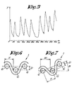
- the matrix system is first of all located in such a way that the matrix columns are parallel to the direction of the weft threads. Afterwards, the 512 values are counted, column after column. This way we get a series of 512 values indicating the total light intensity on each vertical line. These values have a typical pattern illustrated on figure 5, whereby the distance between the successive maximum slopes are corresponding to the distance between the shots.
- the distances between the shots can be automatically determined from the aforesaid values by using a micro-processor. This micro-processor can also attach a numeric value to the checked fabric from the evaluation of these values by using an equation with previously set values.
- the fabric is subdivided in stripes having the thickness of one warp thread. If the method is applied for evaluating the fabric, the odd stripes are for instance treated first and afterwards the even stripes separately.
- a depth measurement is also foreseen.
- the tern "depth measurement” means that the distance where a weft thread 6 is located on a deeper position has a consequence of a relaxation defect by comparison with the normal position of the other weft threads 6.
- the method to be applied is mainly illustrated on figures 6 and 7.
- the depth D is determined by several successive distance measurements. First of all, as illustrated on figure 6, the horizontal distance V is determined. Afterwards the fabric 1 is rotated on an angle B in relationship with the observation direction of the video camera 3. The distance in the present case W is determined again between two successive weft threads 6.
- An angle comprised between 30 and 50 degrees is preferably chosen for B because this value of B generally gives a very contrasting image.
- the depth D will be preferably calculated by taking the average of the results of several measurements which have been carried out with different angles.
Landscapes
- Engineering & Computer Science (AREA)
- Textile Engineering (AREA)
- Chemical & Material Sciences (AREA)
- Life Sciences & Earth Sciences (AREA)
- Biochemistry (AREA)
- Health & Medical Sciences (AREA)
- Physics & Mathematics (AREA)
- Analytical Chemistry (AREA)
- Wood Science & Technology (AREA)
- General Health & Medical Sciences (AREA)
- General Physics & Mathematics (AREA)
- Immunology (AREA)
- Pathology (AREA)
- Materials Engineering (AREA)
- Treatment Of Fiber Materials (AREA)
- Investigating Materials By The Use Of Optical Means Adapted For Particular Applications (AREA)
Description
- The present invention concerns a method for controlling the location of the weft threads in a fabric. This method can be put into practice in a weaving loom immediately after the manufacture of the fabric or on a special check point independently from the weaving loom.
- More particularly, the invention concerns a method designed to indicate a numeric value corresponding to the fabric quality and more specially concerning the position of the weft threads.
- It is already known that a lot of defects can occur in the fabrics as a consequence of a wrong position of the weft threads. Generally speaking, these defects are related to the starting strips which are formed because the fabric is more open or tight at several locations that it should be normally be the case. Further on relaxation and reflection starting strips can also occur if one or several weft threads are located on a too deep position or respectively if one weft thread is inserted into the fabric with an excessive tension.
- It is already known that, in order to track down such defects on the weaving loom and more specially the modifications of the fabric density resulting from such defects, methods can be used that permit to adjust the weaving process. According to the German Patent Application Nr. 3.435.391 this check is carried out on the weaving loom by using a macro lens and a video camera to generate an image of the fabric, whereby this image is digitalized by the use of a matrix and the distances between the weft threads are calculated afterwards.
- This known method has, however, the disadvantage that the fabrics without contrasting aspect cannot be checked by simply using this technique. Indeed, in the case of fabrics with a large fabric density and also in the case of fibrous fabrics, the edges of the weft threads are difficult to distinguish and it is consequently quite impossible to carry out an automatic check in a relatively simple way.
- In order to find a solution to this disadvantage the present invention foresees a method for checking the position of the weft threads of a fabric, whereby the aforesaid disadvantage is systematically avoided.
- To this end the invention relates to a method for controlling the location of the weft threads in a fabric, more specifically for determining the quality of the fabric, comprising the steps of generating an image of the fabric by means of a video camera whereby the image quality is improved by means of a contrast improving illumination; automatically treating the image of the video camera by means of a matrix system, whereby the matrix of the system is located in such a way that the columns are corresponding with the directions of the weft threads, whereby the light intensity of all points is counted alterwards, column after column and whereby the distances between the columns showing the successive maximum slopes of the light intensity curves are used as a measure for the check; and determining out of said treatment a quantitative evalution of the fabric quality in relation with the position of the weft threads.
- The invention also relates to a method for controlling the location of the weft threads in a fabric, more specifically for determining the quality of the fabric, comprising the steps of generating an image by means of a video camera, whereby the image quality is improved by means of a contrast improving illumination; treating the image by means of scaler to carry out a check on the deviations; and determining out of said treatment a quantitative evaluation of the fabric quality in relation with the position of the weft threads.
- According to a first embodiment, the contrast improving illumination mainly comprises the illumination of the fabric in angular position along the side where the video camera is mounted. According to an alternative solution, the contrast improving illumination is mainly achieved by illumination through the fabric.
- According to a special embodiment, the present invention also foresees a depth measurement, whereby the deviation of the position of the weft threads can be measured and calculated from the relaxation defects.
- In order that the characteristics of the invention are better understood, a few preferred layouts will be described hereafter by way of example without any limitative character, whereby use is made of the method of the present invention and with reference to the figures in appendix that represent respectively:
- figure 1 the contrast improving illumination by means of illumination through the fabric, schematically illustrated;
- figure 2 the contrast improving illumination by means of a shew illumination, as schematically illustrated;
- figure 3 the image of the fabric that is seen by the video camera in the case of a shew illumination;
- figure 4 a schematic illustration of the method for checking a complete fabric;
- figure 5 an illustration of the measurement results with use of a metric system;
- figures 6 and 7 illustrations of the method for depth measurements.
- As illustrated on figure 1, the method in accordance with the invention is carried out by illuminating through the
fabric 1 to be evaluted, for instance by placing alight source 2 under this fabric, while avideo camera 3 is directed to the top side of thefabric 1. Thesignals 4 from thevideo camera 3 are treated by a manual orautomatic treatment unit 5. - In the case that the fabric is very tight, preference will be given to the embodiment illustrated on figure 2. In this case, the
light source 2 is located above thefabric 1 in such a way that it is illuminated following a well determined angle A. This way, the advantage is obtained that theweft threads 6 are more strongly illuminated along one side, while on the other side a shadow effect is achieved. Quite obviously, this method results into a sharp and very contrasting image as illustrated on figure 3. - In the case of manual treatment of the image, the
treatment unit 5 will be mainly composed of a scaler. This is a device superimposing two vertical lines and one horizontal reference line onto the image, whereby these three lines can be displaced manually over the image by rotating potentiometers. The method used in this way implies that the two vertical lines are put on two sucessive bright-dark contrast transitions and that the distance between the two vertical lines is recorded. This distance can then be recorded on several locations of the fabric in order to determine the average of the deviations of the weft thread positions. In the case of unlinear contrast transitions, the lines of the scalers are usually shifted on the transition average. - In the case of automatic checking of the location of the
weft threads 6, choice will be preferably made of atreatment unit 5 that is equipped of a metric system. By means of these metric systems the light and dark points of the image of thefabric 1 that has been recorded by means of amacro lens 7 can be digitalized and afterwards read and interpreted according to the desired result. Thefabric 1 is preferably evaluated in a systematic way. As illustrated on figure 4, several images can be taken and treated on points located near each other. This way, it is possible to compare these images with measurements from a perfect fabric. As a result of the measurements carried out on 8 different locations near each other that are all concerning thesame weft threads 6, it is possible to calculate an average from these results in order to get a quantitative evaluation of the fabric quality in relationship with the position of the weft threads. - The aforesaid matrix system can be for instance a matrix of 512 × 512 points, corresponding for about 5 weft threads per image, corresponding to a resolution of about 1% for each weft thread. In order to obtain very quickly reliable results use shall be made of the following algorithm in accordance with the invention. The matrix system is first of all located in such a way that the matrix columns are parallel to the direction of the weft threads. Afterwards, the 512 values are counted, column after column. This way we get a series of 512 values indicating the total light intensity on each vertical line. These values have a typical pattern illustrated on figure 5, whereby the distance between the successive maximum slopes are corresponding to the distance between the shots. The distances between the shots can be automatically determined from the aforesaid values by using a micro-processor. This micro-processor can also attach a numeric value to the checked fabric from the evaluation of these values by using an equation with previously set values.
- In the case of noise rich images, for instance when the assembly is strongly intricated, the determination of the aforesaid maximum slopes may be somewhat difficult because the maxima of the curves are not clearly determined. This trouble can be avoided by replacing each value on each point of the matrix by the average of the value itself and of the value of the adjacent points, whereby, according to the present invention, only the adjacent points located on the same vertical line are preferably taken into account. This counting following vertical lines followed by the determination of the average has an advantage by comparison with the usual points suppressing filter, whereby each point is replaced by the average of its 8 adjacent points because it runs 10 times faster.
- In the case of a fabric with glittering warp threads the fabric is subdivided in stripes having the thickness of one warp thread. If the method is applied for evaluating the fabric, the odd stripes are for instance treated first and afterwards the even stripes separately.
- According to a special aspect of the invention, a depth measurement is also foreseen. The tern "depth measurement" means that the distance where a
weft thread 6 is located on a deeper position has a consequence of a relaxation defect by comparison with the normal position of theother weft threads 6. The method to be applied is mainly illustrated on figures 6 and 7. In this case, the depth D is determined by several successive distance measurements. First of all, as illustrated on figure 6, the horizontal distance V is determined. Afterwards thefabric 1 is rotated on an angle B in relationship with the observation direction of thevideo camera 3. The distance in the present case W is determined again between twosuccessive weft threads 6. The value of D can be calculated from the mathematical equation:

- An angle comprised between 30 and 50 degrees is preferably chosen for B because this value of B generally gives a very contrasting image. The depth D will be preferably calculated by taking the average of the results of several measurements which have been carried out with different angles.
- The present invention is by no means limited to the layouts described by way of examples and illustrated in the figures in appendix but this method for checking the position of the weft thread of a fabric can be put into practice according to different alternative solutions without departing from the scope of the present invention.
Claims (6)
Applications Claiming Priority (2)
| Application Number | Priority Date | Filing Date | Title |
|---|---|---|---|
| NL8601818 | 1986-07-11 | ||
| NL8601818A NL8601818A (en) | 1986-07-11 | 1986-07-11 | METHOD FOR CHECKING THE POSITION OF THE TISSUE THREADS OF A TISSUE |
Publications (2)
| Publication Number | Publication Date |
|---|---|
| EP0252547A1 EP0252547A1 (en) | 1988-01-13 |
| EP0252547B1 true EP0252547B1 (en) | 1991-04-10 |
Family
ID=19848305
Family Applications (1)
| Application Number | Title | Priority Date | Filing Date |
|---|---|---|---|
| EP87201161A Expired - Lifetime EP0252547B1 (en) | 1986-07-11 | 1987-06-17 | Method for controlling the location of the weft threads in a fabric |
Country Status (5)
| Country | Link |
|---|---|
| US (1) | US4791481A (en) |
| EP (1) | EP0252547B1 (en) |
| DE (1) | DE3769215D1 (en) |
| ES (1) | ES2021344B3 (en) |
| NL (1) | NL8601818A (en) |
Families Citing this family (14)
| Publication number | Priority date | Publication date | Assignee | Title |
|---|---|---|---|---|
| DE4142356A1 (en) * | 1990-12-28 | 1992-07-02 | Nissan Motor | WOMB MONITORING SYSTEM FOR A WEAVING MACHINE |
| US5097516A (en) * | 1991-02-28 | 1992-03-17 | At&T Bell Laboratories | Technique for illuminating a surface with a gradient intensity line of light to achieve enhanced two-dimensional imaging |
| US5349385A (en) * | 1992-08-06 | 1994-09-20 | Florida Atlantic University | Adaptive scan converter |
| US5781655A (en) * | 1995-12-15 | 1998-07-14 | Macmillan Bloedel Limited | Strand dimension sensing |
| US5936665A (en) * | 1996-05-22 | 1999-08-10 | Georgia Tech Research Corporation | Automated apparatus for counting pillings in textile fabrics |
| US6738504B1 (en) * | 1999-08-27 | 2004-05-18 | Shinko Electric Industries Co., Ltd | Inspection apparatus for semiconductor device and parts mounter using same |
| BE1014133A3 (en) * | 2001-04-20 | 2003-05-06 | Picanol Nv | Method for optimizing a textile production and establishments to apply this procedure. |
| US6728593B2 (en) * | 2002-06-06 | 2004-04-27 | The Hong Kong Polytechnic University | System for analysis of fabric surface |
| WO2005050194A1 (en) * | 2003-11-21 | 2005-06-02 | Ralph Gregory Burke | A device for inspecting and controlling the density of a moving web of cloth in a production line |
| CN1715551B (en) * | 2004-06-28 | 2010-08-04 | 宫元九 | Method for detecting weft skew of textiles |
| US7755770B2 (en) * | 2006-03-24 | 2010-07-13 | Schlumberger Technology Corporation | Method for mapping geometrical features with opto-electronic arrays |
| JP2020007683A (en) * | 2018-07-12 | 2020-01-16 | 株式会社豊田自動織機 | Woven-fabric inspection apparatus for loom |
| JP2020007682A (en) * | 2018-07-12 | 2020-01-16 | 株式会社豊田自動織機 | Stop-mark inspection apparatus in loom |
| CN112215791B (en) * | 2019-07-12 | 2025-01-24 | 宝洁公司 | A system and method for providing and visualizing textile information |
Family Cites Families (6)
| Publication number | Priority date | Publication date | Assignee | Title |
|---|---|---|---|---|
| GB803843A (en) * | 1956-02-27 | 1958-11-05 | Dornier Gmbh Lindauer | Apparatus for observing moving fabrics |
| GB804099A (en) * | 1956-11-20 | 1958-11-05 | Dornier Gmbh Lindauer | Apparatus for observing moving fabrics |
| BE859668A (en) * | 1977-10-13 | 1978-02-01 | Goossens Gebroeders Nv | TUFT ERROR DETECTION DEVICE |
| JPS5596405A (en) * | 1979-01-19 | 1980-07-22 | Hajime Sangyo Kk | Inspection device for moving object |
| FR2548077B1 (en) * | 1983-06-30 | 1987-03-06 | Gerber Scient Inc | APPARATUS FOR HELPING AN OPERATOR TO SOLVE PROBLEMS POSED BY FAULTS OF FABRICS |
| SE448002B (en) * | 1983-10-07 | 1987-01-12 | Asea Ab | OPTICAL UPPER AND MONITORING OF WOVEN PRODUCTS AT MACHINE WEAR |
-
1986
- 1986-07-11 NL NL8601818A patent/NL8601818A/en not_active Application Discontinuation
-
1987
- 1987-06-17 ES ES87201161T patent/ES2021344B3/en not_active Expired - Lifetime
- 1987-06-17 EP EP87201161A patent/EP0252547B1/en not_active Expired - Lifetime
- 1987-06-17 DE DE8787201161T patent/DE3769215D1/en not_active Expired - Lifetime
- 1987-06-18 US US07/063,316 patent/US4791481A/en not_active Expired - Fee Related
Non-Patent Citations (1)
| Title |
|---|
| "La Grande Encyclopedie", Larousse, 1975, vol. 15, pages 9408-9410 * |
Also Published As
| Publication number | Publication date |
|---|---|
| EP0252547A1 (en) | 1988-01-13 |
| US4791481A (en) | 1988-12-13 |
| DE3769215D1 (en) | 1991-05-16 |
| NL8601818A (en) | 1988-02-01 |
| ES2021344B3 (en) | 1991-11-01 |
Similar Documents
| Publication | Publication Date | Title |
|---|---|---|
| EP0252547A1 (en) | Method for controlling the location of the weft threads in a fabric | |
| Huang et al. | Woven fabric analysis by image processing: Part I: Identification of weave patterns | |
| US11427940B2 (en) | Methods and systems for triggered on-loom fabric inspection | |
| Xu | Instrumental evaluation of fabric pilling | |
| KR102445162B1 (en) | Fabric inspection system | |
| CA1226640A (en) | Method and apparatus for the automatic monitoring of textile fabrics, especially woven fabrics | |
| US5125034A (en) | Method and apparatus for analyzing fabric conditions | |
| US20220341069A1 (en) | Methods and systems for multiple image collection in an on-loom fabric inspection system | |
| DE19511534A1 (en) | Detecting 3=D fault locations with automatic monitoring of specimen surfaces using camera | |
| JP2000018932A (en) | Defect inspection method and inspection device for test object | |
| EP3844332A1 (en) | Method and system for line-by-line one dimensional fabric inspection | |
| DE19813073A1 (en) | Method and device for determining the optical quality and for detecting defects in flat glass and other optically transparent materials, in particular drips, threads and lines | |
| KR20230137584A (en) | Vision inspection system for defect detection of fabric | |
| PT741290E (en) | METHOD AND APPARATUS FOR DETERMINING THE MOTION DIALING ANGLES IN MOTION OR SIMILAR APPLICATIONS | |
| CN109632817B (en) | Fabric weaving on-line defect detection method based on collimated laser beam | |
| CA2520444A1 (en) | Method for inspecting the quality criteria of flat textile structures embodied in a multilayer form according to a contour | |
| CN121527080A (en) | A Machine Vision-Based Method for Detecting and Adaptively Compensating for Stitch Defects in Industrial Sewing Machines | |
| EP0275229A1 (en) | Method and device for automatically detecting and measuring the position of the forms or nuances of an image produced by a video camera | |
| US6628807B1 (en) | Method and equipment for testing the color and reflectivity of high-visibility garments | |
| DE10019387C2 (en) | Tire inspection method and apparatus | |
| JPH0540099A (en) | Fluff inspection device | |
| DE19733775A1 (en) | Measuring surface roughness of reflective material, e.g. paper | |
| DE19924840A1 (en) | Apparatus for determining the degree of hairiness of textile products obtains the result with the relative frequency of incidence of hair length classes and the moment of distribution of this frequency taken into account | |
| US6936836B2 (en) | Method and apparatus for examining fiber material traveling in a fiber processing machine | |
| TWI864479B (en) | Cloth surface examination method of dual cameras and device thereof |
Legal Events
| Date | Code | Title | Description |
|---|---|---|---|
| PUAI | Public reference made under article 153(3) epc to a published international application that has entered the european phase |
Free format text: ORIGINAL CODE: 0009012 |
|
| AK | Designated contracting states |
Kind code of ref document: A1 Designated state(s): BE CH DE ES FR GB IT LI LU |
|
| 17P | Request for examination filed |
Effective date: 19880204 |
|
| 17Q | First examination report despatched |
Effective date: 19890824 |
|
| GRAA | (expected) grant |
Free format text: ORIGINAL CODE: 0009210 |
|
| ITF | It: translation for a ep patent filed | ||
| AK | Designated contracting states |
Kind code of ref document: B1 Designated state(s): BE CH DE ES FR GB IT LI LU |
|
| ET | Fr: translation filed | ||
| REF | Corresponds to: |
Ref document number: 3769215 Country of ref document: DE Date of ref document: 19910516 |
|
| PG25 | Lapsed in a contracting state [announced via postgrant information from national office to epo] |
Ref country code: ES Free format text: LAPSE BECAUSE OF THE APPLICANT RENOUNCES Effective date: 19910618 |
|
| PG25 | Lapsed in a contracting state [announced via postgrant information from national office to epo] |
Ref country code: LU Free format text: LAPSE BECAUSE OF NON-PAYMENT OF DUE FEES Effective date: 19910630 Ref country code: LI Effective date: 19910630 Ref country code: CH Effective date: 19910630 Ref country code: BE Effective date: 19910630 |
|
| PG25 | Lapsed in a contracting state [announced via postgrant information from national office to epo] |
Ref country code: GB Effective date: 19910710 |
|
| BERE | Be: lapsed |
Owner name: PICANOL N.V. Effective date: 19910630 |
|
| PLBE | No opposition filed within time limit |
Free format text: ORIGINAL CODE: 0009261 |
|
| STAA | Information on the status of an ep patent application or granted ep patent |
Free format text: STATUS: NO OPPOSITION FILED WITHIN TIME LIMIT |
|
| PG25 | Lapsed in a contracting state [announced via postgrant information from national office to epo] |
Ref country code: FR Effective date: 19920228 |
|
| REG | Reference to a national code |
Ref country code: CH Ref legal event code: PL |
|
| GBPC | Gb: european patent ceased through non-payment of renewal fee | ||
| PG25 | Lapsed in a contracting state [announced via postgrant information from national office to epo] |
Ref country code: DE Effective date: 19920401 |
|
| 26N | No opposition filed | ||
| REG | Reference to a national code |
Ref country code: FR Ref legal event code: ST |
|
| REG | Reference to a national code |
Ref country code: ES Ref legal event code: FD2A Effective date: 19991007 |
|
| PG25 | Lapsed in a contracting state [announced via postgrant information from national office to epo] |
Ref country code: IT Free format text: LAPSE BECAUSE OF NON-PAYMENT OF DUE FEES;WARNING: LAPSES OF ITALIAN PATENTS WITH EFFECTIVE DATE BEFORE 2007 MAY HAVE OCCURRED AT ANY TIME BEFORE 2007. THE CORRECT EFFECTIVE DATE MAY BE DIFFERENT FROM THE ONE RECORDED. Effective date: 20050617 |