US5936665A - Automated apparatus for counting pillings in textile fabrics - Google Patents
Automated apparatus for counting pillings in textile fabrics Download PDFInfo
- Publication number
- US5936665A US5936665A US08/859,443 US85944397A US5936665A US 5936665 A US5936665 A US 5936665A US 85944397 A US85944397 A US 85944397A US 5936665 A US5936665 A US 5936665A
- Authority
- US
- United States
- Prior art keywords
- fabric
- pilling
- pillings
- image
- sample
- Prior art date
- Legal status (The legal status is an assumption and is not a legal conclusion. Google has not performed a legal analysis and makes no representation as to the accuracy of the status listed.)
- Expired - Fee Related
Links
- 239000004744 fabric Substances 0.000 title claims abstract description 100
- 239000004753 textile Substances 0.000 title claims abstract description 11
- 238000000034 method Methods 0.000 claims abstract description 21
- 238000001514 detection method Methods 0.000 claims description 28
- 238000003908 quality control method Methods 0.000 claims description 13
- 238000012545 processing Methods 0.000 claims description 9
- 238000009826 distribution Methods 0.000 claims description 6
- 238000012360 testing method Methods 0.000 claims description 4
- 238000001914 filtration Methods 0.000 claims description 3
- 229910052754 neon Inorganic materials 0.000 claims description 2
- GKAOGPIIYCISHV-UHFFFAOYSA-N neon atom Chemical compound [Ne] GKAOGPIIYCISHV-UHFFFAOYSA-N 0.000 claims description 2
- 230000001131 transforming effect Effects 0.000 claims description 2
- 238000001454 recorded image Methods 0.000 claims 1
- 230000000007 visual effect Effects 0.000 abstract description 2
- 238000007689 inspection Methods 0.000 abstract 1
- 229910052704 radon Inorganic materials 0.000 description 7
- SYUHGPGVQRZVTB-UHFFFAOYSA-N radon atom Chemical compound [Rn] SYUHGPGVQRZVTB-UHFFFAOYSA-N 0.000 description 7
- 238000005286 illumination Methods 0.000 description 4
- 230000000877 morphologic effect Effects 0.000 description 4
- 238000011179 visual inspection Methods 0.000 description 3
- 238000010586 diagram Methods 0.000 description 2
- 238000003384 imaging method Methods 0.000 description 2
- 238000013519 translation Methods 0.000 description 2
- 244000261422 Lysimachia clethroides Species 0.000 description 1
- 230000002745 absorbent Effects 0.000 description 1
- 239000002250 absorbent Substances 0.000 description 1
- 239000003086 colorant Substances 0.000 description 1
- 238000007796 conventional method Methods 0.000 description 1
- 230000010339 dilation Effects 0.000 description 1
- 230000000694 effects Effects 0.000 description 1
- 230000003628 erosive effect Effects 0.000 description 1
- 238000002474 experimental method Methods 0.000 description 1
- 230000010354 integration Effects 0.000 description 1
- 238000004519 manufacturing process Methods 0.000 description 1
- 238000005406 washing Methods 0.000 description 1
Images


Classifications
-
- G—PHYSICS
- G01—MEASURING; TESTING
- G01N—INVESTIGATING OR ANALYSING MATERIALS BY DETERMINING THEIR CHEMICAL OR PHYSICAL PROPERTIES
- G01N21/00—Investigating or analysing materials by the use of optical means, i.e. using sub-millimetre waves, infrared, visible or ultraviolet light
- G01N21/84—Systems specially adapted for particular applications
- G01N21/88—Investigating the presence of flaws or contamination
- G01N21/89—Investigating the presence of flaws or contamination in moving material, e.g. running paper or textiles
- G01N21/8901—Optical details; Scanning details
- G01N21/8903—Optical details; Scanning details using a multiple detector array
-
- G—PHYSICS
- G01—MEASURING; TESTING
- G01N—INVESTIGATING OR ANALYSING MATERIALS BY DETERMINING THEIR CHEMICAL OR PHYSICAL PROPERTIES
- G01N21/00—Investigating or analysing materials by the use of optical means, i.e. using sub-millimetre waves, infrared, visible or ultraviolet light
- G01N21/84—Systems specially adapted for particular applications
- G01N21/88—Investigating the presence of flaws or contamination
- G01N21/89—Investigating the presence of flaws or contamination in moving material, e.g. running paper or textiles
- G01N21/892—Investigating the presence of flaws or contamination in moving material, e.g. running paper or textiles characterised by the flaw, defect or object feature examined
- G01N21/898—Irregularities in textured or patterned surfaces, e.g. textiles, wood
- G01N21/8983—Irregularities in textured or patterned surfaces, e.g. textiles, wood for testing textile webs, i.e. woven material
-
- G—PHYSICS
- G06—COMPUTING; CALCULATING OR COUNTING
- G06M—COUNTING MECHANISMS; COUNTING OF OBJECTS NOT OTHERWISE PROVIDED FOR
- G06M1/00—Design features of general application
- G06M1/08—Design features of general application for actuating the drive
- G06M1/10—Design features of general application for actuating the drive by electric or magnetic means
- G06M1/101—Design features of general application for actuating the drive by electric or magnetic means by electro-optical means
-
- G—PHYSICS
- G06—COMPUTING; CALCULATING OR COUNTING
- G06M—COUNTING MECHANISMS; COUNTING OF OBJECTS NOT OTHERWISE PROVIDED FOR
- G06M11/00—Counting of objects distributed at random, e.g. on a surface
-
- G—PHYSICS
- G06—COMPUTING; CALCULATING OR COUNTING
- G06T—IMAGE DATA PROCESSING OR GENERATION, IN GENERAL
- G06T7/00—Image analysis
- G06T7/0002—Inspection of images, e.g. flaw detection
- G06T7/0004—Industrial image inspection
- G06T7/001—Industrial image inspection using an image reference approach
-
- G—PHYSICS
- G06—COMPUTING; CALCULATING OR COUNTING
- G06T—IMAGE DATA PROCESSING OR GENERATION, IN GENERAL
- G06T2207/00—Indexing scheme for image analysis or image enhancement
- G06T2207/20—Special algorithmic details
- G06T2207/20021—Dividing image into blocks, subimages or windows
-
- G—PHYSICS
- G06—COMPUTING; CALCULATING OR COUNTING
- G06T—IMAGE DATA PROCESSING OR GENERATION, IN GENERAL
- G06T2207/00—Indexing scheme for image analysis or image enhancement
- G06T2207/20—Special algorithmic details
- G06T2207/20048—Transform domain processing
-
- G—PHYSICS
- G06—COMPUTING; CALCULATING OR COUNTING
- G06T—IMAGE DATA PROCESSING OR GENERATION, IN GENERAL
- G06T2207/00—Indexing scheme for image analysis or image enhancement
- G06T2207/30—Subject of image; Context of image processing
- G06T2207/30108—Industrial image inspection
- G06T2207/30124—Fabrics; Textile; Paper
Definitions
- the present invention relates generally to quality control systems and more particularly to new imaging, data processing, signal processing and fuzzy logic-based techniques as applied to an apparatus and method for counting automatically the number of pillings present in fabric samples for quality control purposes.
- Textile fabrics vary widely in thickness, texture and color patterns. To insure the quality of such fabrics, textile manufacturers utilize human inspectors to manually inspect samples of finished bolts of fabric. These inspectors utilize a rating system to classify the samples, with Class 1 rating being the lowest, or poorest quality rating and Class 5 rating being the highest, or best quality rating.
- One of the major areas of concern for textile manufacturers is the number of pillings associated with a particular piece of fabric subsequent to the fabric being subjected to repeated washings. From a quality control standpoint, different types of fabric have different associated acceptable pilling counts. Typically, the more pillings present on the surface of the fabric, the lower the quality of the fabric.
- Inspectors have for years used a subjective visual inspection method of determining the rating of these pieces of fabric. Human error is inherently introduced into such a system, as inspectors must subjectively determine the quality of the fabric through their own visual inspection. As a result, different inspectors may have their own individual idea of what constitutes a Class 1 rating, Class 2 rating, Class 3 rating, Class 4 rating, or Class 5 rating. Therefore, a single piece of fabric may be given a different rating by each of the several inspectors rating that piece of fabric. Inherently, such a rating system tends to produce inconsistent quality control results.
- the present invention overcomes the above-mentioned limitations by providing an apparatus and method for automatically counting the number of pillings on textile fabrics.
- the present invention provides an apparatus and corresponding software with minimal set-ups; an imaging and data processing software procedure for counting the number of pillings; and a methodology for classifying the fabric samples into one of the pre-defined classes with repeatable accuracy while accounting for human judgment by allowing the determination of the degree of confidence assigned to the sample's membership in each class.
- the present invention utilizes a CCD array camera for detecting pillings on a sample bolt of fabric mounted on a fabric sample feeding mechanism and rotated by a driver stepper motor.
- the apparatus employs two possible configurations with the first one using an ultraviolet (UV) light source and dark background for light color samples and the second using a neon light source and white background for dark colored samples.
- Processing software requires as input the relative thickness of the fabric for necessary adjustments of the windowed image.
- the camera captures successive images of the fabric sample as the sample is rotated via the controlled driving mechanism exposing consecutive sections of the fabric samples to the camera's field of view. These images are processed to count the number of pillings on the sample fabric. Counts thus obtained through repeated experiments on a large number of samples are used to develop fuzzy membership functions corresponding to five quality classes accepted as standards in the textile industry. Expert operators (inspectors) are used to classify the test fabric samples into one of five quality classes. A histogram is developed first from this statistical data and converted to fuzzy membership functions. A count obtained for a new sample is fuzzified and represents the membership of the sample to various classes. Thus, through the use of fuzzy logic, the captured image data is processed and compared to historical fuzzy distributions stored as templates in a computer.
- the fuzzy membership function for the sample tested models is compared to the subjective judgment of experienced operators and the fabric is then given a class rating of 1 to 5 based on this fuzzy logic-based comparison. If the fuzzy membership functions of the tested sample overlaps more than one of the five template distributions, then a degree of confidence is assigned to signify the extent of its membership to each overlapping class.
- FIG. 1 illustrates system components in a preferred embodiment of the present invention
- FIG. 2 illustrates a flow diagram illustrating the steps involved in implementing the automatic pilling detection procedure according to a preferred embodiment of the present invention
- FIG. 3 is a graphical representation of the input image captured by the system camera and input into the system processor
- FIG. 4 illustrates a histogram of the input image shown in FIG. 3
- FIG. 5 illustrates a segmented portion of the input image shown in FIG. 3
- FIG. 6 illustrates a radon transform of the segmented image shown in FIG. 5;
- FIG. 7 illustrates the radon transform of FIG. 6 after morphological filtering
- FIG. 8 illustrates a graphical representation of the data in FIG. 7 subsequent to detrending of the data
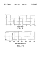
- FIG. 9 illustrates a graphical representation of the detected pillings determined from the input image shown in FIG. 3;
- FIG. 10 illustrates pilling mask for the next image taken by the image camera of the sample fabric
- FIGS. 11a through 11e are histograms of historical occurrences of Class 1-Class 5 ratings, respectively, for pilling counts of the fabric samples as selected by human inspectors and as determined by the present invention.
- FIG. 12 is a representation of fuzzy membership functions.
- the universe of discourse of the memberships is the pilling count.
- the figure illustrates the membership function for the five classes over the universe of discourse.
- FIG. 1 illustrates an automatic pilling detection system generally at 10.
- the system 10 is implemented through both hardware and software to count the number of pillings associated with a sample fabric in a manner that gives consistent results for fabrics of a variety of colors and textures.
- the system 10 thereby gives a high degree of objectivity to a quality control system that has historically been implemented through visual checking of the fabric by human inspectors, and thus which thereby has a very high degree of associated subjectivity.
- the automatic pilling detection system of the present invention involves application and integration of a state of the art machine vision system, automated fabric feed mechanism, and a processor for computation and control purposes, as will now be described in more detail.
- the vision system consists of a Pulnix CCD gray scale camera 12 having a Cannon 16-100 mm variable zoom lens with 1.25 in ⁇ 1.25 in field-of-view and 640 pixel by 480 pixel resolution.
- An ultra-violet (UV) light source 14 is used with the camera for front directional illumination.
- An image grabber 16 with thirty frames/second translation is also implemented with the camera lens.
- the variable zoom lens and camera are used to finalize the field of view, depth of field, and focal length. These parameters may be adjusted once so that the image resolution for pilling detection of a particular type of fabric such as the fabric shown at 18 satisfies a specified lower bound. Flexibility for such parameter adjustment has been provided in the camera and light mounting system. More than one camera may be used to capture a longer image.
- the directional illumination ultra-violet light source 14 was selected after experimentation with different types of light sources including diffused light, goose necks, back-lighting, and front-lighting. UV light provides the best contrast between the image of the fabric 18 and the background. A good reflector 20 for UV light is used as a background for dark colored fabric, and a good absorbent 22 is used for light colored fabric.
- the data translation image grabber 16 is used for on-line capturing of the image. A two dimensional 256 gray scale image of the fabric sample is recorded. A number of image processing steps are performed over the captured image for correct determination of the pilling count as discussed in the software description below.
- the fabric feed mechanism consists of a feed forward/backward stepper motor 26 operatively connected to a rotatable mounting 28 to which the fabric sample is affixed.
- the mounting is controlled by a RS232 compatible position controller.
- the fabric feed mechanism is adjusted so that a correct pilling count is obtained with minimum stepping of the feed mechanism.
- a provision in the control logic is provided for adjustment of the feed step size as it may require changes for various fabric types.
- Another important feature of the control logic is the generation of a mask for each image which prevent pillings to be counted more than once in consecutive images.
- a 90 M Hz pentium machine 30 with 16 MB RAM is preferably used as a platform for image processing, control and coordination of the feed mechanism and vision system. All image processing and control methods are developed in Borland C.
- the front end of the system used by the operator consists of graphical displays indicating different logical steps of the pilling count apparatus and method of the present invention. It also prompts the operator for simple key in operations for one time positioning of the motor, light, and camera at correct locations at the start of the automatic count procedure.
- a two dimensional, 256 gray scale image of the fabric is captured using the CCD camera.
- a sample image is shown in FIG. 3.
- An ultra violet light source is used as front directional illumination.
- a pre-programmed rectangular window is used to select the region of interest in the captured image with the 640 ⁇ 480 pixel resolution camera.
- the window is preferably 640 ⁇ 50 pixels. However, the window dimensions may be varied according to the particular application.
- the selected region of the image called sub-image, is used.
- a histogram analysis such as that represented in FIG. 4, is performed on the sub-image, and a threshold value is determined automatically.
- the threshold value selection accommodates the illumination variations as long as a good contrasted image can be captured.
- the calculated threshold value shown in FIG. 5, is then used to segment the sub-image into the background and the fabric.
- the radon transform converts a two-dimensional image into a one-dimensional signal by taking the integral of the two-dimensional image along a specified direction.
- the radon transform is applied along the vertical direction of the segmented sub-image as shown graphically in FIG. 6.
- a nonlinear morphological filter has been designed. This filter performs a series of erosion and dilation operations on the radon transformed signal. The resulting signal is shown in FIG. 7.
- the structuring element for these morphological operations is designed such that fuzz balls (which are not pillings) are filtered out.
- step 50 sometimes the fabric is not uniform along the full length of the roller. This is common for thick fabrics and may result in an incorrect pilling count.
- detrending is performed to remove the non-uniform mounting effect from the morphologically filtered signal. This is done by subtracting the linear trend from the morphologically filtered signal. A least square estimation is performed to determine the linear trend of the signal.
- pillings are detected by counting the connecting segments of the detrended signal above a pre-determined threshold.
- the value of this threshold depends upon the smallest pilling which must be determined.
- a mask is generated for each sub-image.
- the mask of a sub-image represents the location of the detected pillings. To determine the total number of pillings on the fabric, it is sometimes possible that a pilling be viewed more than once but should be counted only once in total count.
- the mask of the current image is compared with the mask of the previous image. Pillings found at the same location in both images are counted only once. Subsequently, a mask is generated from the next image as indicated at step 56.
- the pilling count is fuzzified to represent the membership of the sample to fabric ratings of 1 to 5.
- FIG. 11 a distribution of actual pilling counts obtained by the present invention for numerous manually classified samples is shown.
- Such ratings data represents the data typically input into and stored by the system database.
- the fuzzy class membership if assigned to a sample piece of fabric according to the pilling count detected and based on the human classification available in the historical database, as will now be described.
- a specific pilling count may historically have been given different ratings for a particular type of fabric sample.
- human inspectors have given a Class 1 rating to fabric samples when a pilling count has ranged from about 25 to almost 80 pillings.
- inspectors have given fabric samples a Class 3 rating when the pilling count has ranged from about 8 to almost 42.
- the system of the present invention assigns a fuzzy membership to the five classes, indicated along the left of the graph in FIG. 12, to each pilling count value indicated along the bottom of the graph.
- a membership of about 0.4 is given to Class 4 rating
- a membership of about 0.4 is given to a Class 3 rating
- a membership of about 0.2 is given to a Class 2 rating.
- a membership of 0.35 is given to a Class 3 rating
- a membership of about 0.9 is given to a Class 2 rating.
- This fuzzy membership value represents the degree of confidence associated with a certain classification.
- the degree of confidence associated with Class 2 is 0.9 while it is only 0.35 for Class 3.
- the degree of confidence for Classes 1, 4 and 5 is zero for this case.
- a look-up table implemented at the system controller is utilized to determine the overall sample class rating given the fuzzy membership values for Classes 1-5 associated with the sample.
- the overall sample class ratings for fabrics of various textures can be programmed into the controller in accordance with particular quality control needs.
Landscapes
- Engineering & Computer Science (AREA)
- Physics & Mathematics (AREA)
- General Physics & Mathematics (AREA)
- Textile Engineering (AREA)
- Theoretical Computer Science (AREA)
- Life Sciences & Earth Sciences (AREA)
- Pathology (AREA)
- General Health & Medical Sciences (AREA)
- Immunology (AREA)
- Health & Medical Sciences (AREA)
- Chemical & Material Sciences (AREA)
- Analytical Chemistry (AREA)
- Biochemistry (AREA)
- Quality & Reliability (AREA)
- Wood Science & Technology (AREA)
- Computer Vision & Pattern Recognition (AREA)
- Treatment Of Fiber Materials (AREA)
- Investigating Materials By The Use Of Optical Means Adapted For Particular Applications (AREA)
Abstract
An automated system and associated method of counting pillings in textile fabrics. Images of consecutive sections of a fabric sample are captured by a CCD camera. A system processor then processes the images to enhance image quality. Pillings on the processed, captured fabric sample images are counted, and the resulting data is fuzzified to determine the membership of the data in one or more of a plurality of fabric classes. The present invention provides an objective rating system and method with repeatable accuracy for fabric samples that eliminates the inherent subjectivity associated with conventional manual visual fabric inspection methods.
Description
This application is based upon and claims priority to United States Provisional Patent Application Ser. No. 60/017,702 filed May 22, 1996, and entitled Automated Apparatus for Counting Pillings in Textile Fabrics, the specification and drawings of which are herein expressly incorporated by reference.
1. Technical Field
The present invention relates generally to quality control systems and more particularly to new imaging, data processing, signal processing and fuzzy logic-based techniques as applied to an apparatus and method for counting automatically the number of pillings present in fabric samples for quality control purposes.
2. Discussion
Textile fabrics vary widely in thickness, texture and color patterns. To insure the quality of such fabrics, textile manufacturers utilize human inspectors to manually inspect samples of finished bolts of fabric. These inspectors utilize a rating system to classify the samples, with Class 1 rating being the lowest, or poorest quality rating and Class 5 rating being the highest, or best quality rating.
One of the major areas of concern for textile manufacturers is the number of pillings associated with a particular piece of fabric subsequent to the fabric being subjected to repeated washings. From a quality control standpoint, different types of fabric have different associated acceptable pilling counts. Typically, the more pillings present on the surface of the fabric, the lower the quality of the fabric.
Inspectors have for years used a subjective visual inspection method of determining the rating of these pieces of fabric. Human error is inherently introduced into such a system, as inspectors must subjectively determine the quality of the fabric through their own visual inspection. As a result, different inspectors may have their own individual idea of what constitutes a Class 1 rating, Class 2 rating, Class 3 rating, Class 4 rating, or Class 5 rating. Therefore, a single piece of fabric may be given a different rating by each of the several inspectors rating that piece of fabric. Inherently, such a rating system tends to produce inconsistent quality control results.
Therefore, what is needed is an apparatus and method for producing a more objective analysis of textile fabrics to ensure more consistent quality control ratings for the fabrics, and therefore a better overall quality control system.
The present invention overcomes the above-mentioned limitations by providing an apparatus and method for automatically counting the number of pillings on textile fabrics. The present invention provides an apparatus and corresponding software with minimal set-ups; an imaging and data processing software procedure for counting the number of pillings; and a methodology for classifying the fabric samples into one of the pre-defined classes with repeatable accuracy while accounting for human judgment by allowing the determination of the degree of confidence assigned to the sample's membership in each class.
The present invention utilizes a CCD array camera for detecting pillings on a sample bolt of fabric mounted on a fabric sample feeding mechanism and rotated by a driver stepper motor. The apparatus employs two possible configurations with the first one using an ultraviolet (UV) light source and dark background for light color samples and the second using a neon light source and white background for dark colored samples. Processing software requires as input the relative thickness of the fabric for necessary adjustments of the windowed image.
The camera captures successive images of the fabric sample as the sample is rotated via the controlled driving mechanism exposing consecutive sections of the fabric samples to the camera's field of view. These images are processed to count the number of pillings on the sample fabric. Counts thus obtained through repeated experiments on a large number of samples are used to develop fuzzy membership functions corresponding to five quality classes accepted as standards in the textile industry. Expert operators (inspectors) are used to classify the test fabric samples into one of five quality classes. A histogram is developed first from this statistical data and converted to fuzzy membership functions. A count obtained for a new sample is fuzzified and represents the membership of the sample to various classes. Thus, through the use of fuzzy logic, the captured image data is processed and compared to historical fuzzy distributions stored as templates in a computer. The fuzzy membership function for the sample tested models is compared to the subjective judgment of experienced operators and the fabric is then given a class rating of 1 to 5 based on this fuzzy logic-based comparison. If the fuzzy membership functions of the tested sample overlaps more than one of the five template distributions, then a degree of confidence is assigned to signify the extent of its membership to each overlapping class.
FIG. 1 illustrates system components in a preferred embodiment of the present invention;
FIG. 2 illustrates a flow diagram illustrating the steps involved in implementing the automatic pilling detection procedure according to a preferred embodiment of the present invention;
FIG. 3 is a graphical representation of the input image captured by the system camera and input into the system processor;
FIG. 4 illustrates a histogram of the input image shown in FIG. 3;
FIG. 5 illustrates a segmented portion of the input image shown in FIG. 3;
FIG. 6 illustrates a radon transform of the segmented image shown in FIG. 5;
FIG. 7 illustrates the radon transform of FIG. 6 after morphological filtering;
FIG. 8 illustrates a graphical representation of the data in FIG. 7 subsequent to detrending of the data;
FIG. 9 illustrates a graphical representation of the detected pillings determined from the input image shown in FIG. 3;
FIG. 10 illustrates pilling mask for the next image taken by the image camera of the sample fabric;
FIGS. 11a through 11e are histograms of historical occurrences of Class 1-Class 5 ratings, respectively, for pilling counts of the fabric samples as selected by human inspectors and as determined by the present invention; and
FIG. 12 is a representation of fuzzy membership functions. The universe of discourse of the memberships is the pilling count. The figure illustrates the membership function for the five classes over the universe of discourse.
Referring now to the drawings, FIG. 1 illustrates an automatic pilling detection system generally at 10. As will be described in detail below, the system 10 is implemented through both hardware and software to count the number of pillings associated with a sample fabric in a manner that gives consistent results for fabrics of a variety of colors and textures. The system 10 thereby gives a high degree of objectivity to a quality control system that has historically been implemented through visual checking of the fabric by human inspectors, and thus which thereby has a very high degree of associated subjectivity.
The automatic pilling detection system of the present invention involves application and integration of a state of the art machine vision system, automated fabric feed mechanism, and a processor for computation and control purposes, as will now be described in more detail.
Vision System
The vision system consists of a Pulnix CCD gray scale camera 12 having a Cannon 16-100 mm variable zoom lens with 1.25 in×1.25 in field-of-view and 640 pixel by 480 pixel resolution. An ultra-violet (UV) light source 14 is used with the camera for front directional illumination. An image grabber 16 with thirty frames/second translation is also implemented with the camera lens. The variable zoom lens and camera are used to finalize the field of view, depth of field, and focal length. These parameters may be adjusted once so that the image resolution for pilling detection of a particular type of fabric such as the fabric shown at 18 satisfies a specified lower bound. Flexibility for such parameter adjustment has been provided in the camera and light mounting system. More than one camera may be used to capture a longer image.
Ultra-Violet Light Source
The directional illumination ultra-violet light source 14 was selected after experimentation with different types of light sources including diffused light, goose necks, back-lighting, and front-lighting. UV light provides the best contrast between the image of the fabric 18 and the background. A good reflector 20 for UV light is used as a background for dark colored fabric, and a good absorbent 22 is used for light colored fabric.
Image Grabber
The data translation image grabber 16 is used for on-line capturing of the image. A two dimensional 256 gray scale image of the fabric sample is recorded. A number of image processing steps are performed over the captured image for correct determination of the pilling count as discussed in the software description below.
Feed Mechanism
The fabric feed mechanism consists of a feed forward/backward stepper motor 26 operatively connected to a rotatable mounting 28 to which the fabric sample is affixed. The mounting is controlled by a RS232 compatible position controller. The fabric feed mechanism is adjusted so that a correct pilling count is obtained with minimum stepping of the feed mechanism. A provision in the control logic is provided for adjustment of the feed step size as it may require changes for various fabric types. Another important feature of the control logic is the generation of a mask for each image which prevent pillings to be counted more than once in consecutive images.
A 90 M Hz pentium machine 30 with 16 MB RAM is preferably used as a platform for image processing, control and coordination of the feed mechanism and vision system. All image processing and control methods are developed in Borland C. The front end of the system used by the operator consists of graphical displays indicating different logical steps of the pilling count apparatus and method of the present invention. It also prompts the operator for simple key in operations for one time positioning of the motor, light, and camera at correct locations at the start of the automatic count procedure.
With reference to the flow diagram 40 in FIG. 2, the various logical steps involved in automatic detection of fabric pillings programmed into the system processor are described below:
Image Capturing
At step 42, a two dimensional, 256 gray scale image of the fabric is captured using the CCD camera. A sample image is shown in FIG. 3. An ultra violet light source is used as front directional illumination.
Windowing
At step 44, a pre-programmed rectangular window is used to select the region of interest in the captured image with the 640×480 pixel resolution camera. The window is preferably 640×50 pixels. However, the window dimensions may be varied according to the particular application. For the rest of the processing steps, the selected region of the image, called sub-image, is used.
Auto-Adaptive Threshholding
Referring to FIGS. 4 and 5, at step 44, a histogram analysis, such as that represented in FIG. 4, is performed on the sub-image, and a threshold value is determined automatically. The threshold value selection accommodates the illumination variations as long as a good contrasted image can be captured. The calculated threshold value, shown in FIG. 5, is then used to segment the sub-image into the background and the fabric.
Radon Transforming
At step 46, the radon transform converts a two-dimensional image into a one-dimensional signal by taking the integral of the two-dimensional image along a specified direction. For pilling detection, the radon transform is applied along the vertical direction of the segmented sub-image as shown graphically in FIG. 6.
Nonlinear Morphological Filtering
At step 48, to filter out the noise from the radon transformed sub-image, a nonlinear morphological filter has been designed. This filter performs a series of erosion and dilation operations on the radon transformed signal. The resulting signal is shown in FIG. 7. The structuring element for these morphological operations is designed such that fuzz balls (which are not pillings) are filtered out.
Detrending
Referring to step 50, sometimes the fabric is not uniform along the full length of the roller. This is common for thick fabrics and may result in an incorrect pilling count. As shown in FIG. 8, detrending is performed to remove the non-uniform mounting effect from the morphologically filtered signal. This is done by subtracting the linear trend from the morphologically filtered signal. A least square estimation is performed to determine the linear trend of the signal.
Pilling Detecting
Referring to FIG. 9 at step 52, pillings are detected by counting the connecting segments of the detrended signal above a pre-determined threshold. The value of this threshold depends upon the smallest pilling which must be determined.
Mask Generating
Referring to FIG. 10, a mask is generated for each sub-image. The mask of a sub-image represents the location of the detected pillings. To determine the total number of pillings on the fabric, it is sometimes possible that a pilling be viewed more than once but should be counted only once in total count. As indicated at step 54, the mask of the current image is compared with the mask of the previous image. Pillings found at the same location in both images are counted only once. Subsequently, a mask is generated from the next image as indicated at step 56.
Once the pilling count has been found after the above-mentioned software steps, the pilling count is fuzzified to represent the membership of the sample to fabric ratings of 1 to 5. Referring to FIG. 11, a distribution of actual pilling counts obtained by the present invention for numerous manually classified samples is shown. Such ratings data represents the data typically input into and stored by the system database. The fuzzy class membership if assigned to a sample piece of fabric according to the pilling count detected and based on the human classification available in the historical database, as will now be described.
As shown in the histogram in FIG. 11, a specific pilling count may historically have been given different ratings for a particular type of fabric sample. For example, referring to the histogram in FIG. 11a, human inspectors have given a Class 1 rating to fabric samples when a pilling count has ranged from about 25 to almost 80 pillings. Referring to the histogram in FIG. 11d, inspectors have given fabric samples a Class 3 rating when the pilling count has ranged from about 8 to almost 42. These histograms thus illustrate the inconsistent results of the conventional method of subjective human visual inspection of fabric samples.
Referring to FIG. 12, the system of the present invention assigns a fuzzy membership to the five classes, indicated along the left of the graph in FIG. 12, to each pilling count value indicated along the bottom of the graph. For example, for a pilling count 15, a membership of about 0.4 is given to Class 4 rating, a membership of about 0.4 is given to a Class 3 rating, and a membership of about 0.2 is given to a Class 2 rating. Similarly, for a pilling count of 30, a membership of 0.35 is given to a Class 3 rating and a membership of about 0.9 is given to a Class 2 rating. This fuzzy membership value represents the degree of confidence associated with a certain classification. Thus, for a pilling count of 30, the degree of confidence associated with Class 2 is 0.9 while it is only 0.35 for Class 3. The degree of confidence for Classes 1, 4 and 5 is zero for this case.
A look-up table implemented at the system controller is utilized to determine the overall sample class rating given the fuzzy membership values for Classes 1-5 associated with the sample. The overall sample class ratings for fabrics of various textures can be programmed into the controller in accordance with particular quality control needs.
While the above description constitutes the preferred embodiment of the present invention, it should be appreciated that the invention may be modified without departing from the proper scope or fair meaning of the invention.
Claims (23)
1. A pilling detection system, comprising:
a pilling detection device that detects pillings which are distributed across a fabric sample;
a feed mechanism that provides the fabric sample to the pilling detection device at a predetermined feed rate; and
a processor that controls the predetermined feed rate of the feed mechanism and that assigns a class rating to the fabric sample based on comparing the number of pillings detected by the pilling detection device to stored historical classification data, said processor being programmed with fuzzy logic to determine said class rating based upon how said pillings are distributed across said fabric sample.
2. The pilling detection system of claim 1, wherein the stored historical classification data comprises a plurality of fuzzy membership values that represents historical classifications for a plurality of fabric samples of like color and texture.
3. The pilling detection system of claim 2, wherein the stored historical classification data further comprises a plurality of histograms programmed into the processor that represent a range of pilling counts associated with the plurality of sets of fuzzy membership values.
4. The pilling detection system of claim 2, further comprising a plurality of sets of fuzzy membership values each representing historical classifications for a plurality of fabric samples of like color and texture.
5. The pilling detection system of claim 4, wherein the stored historical classification data further comprises a plurality of histograms programmed into the processor that represent a range of pilling counts associated with each of the plurality of sets of fuzzy membership values.
6. The pilling detection system of claim 2, further comprising a look-up table programmed into the processor that enables the processor to determine a class rating for the test fabric sample based on a comparison of the fuzzy membership values for the number of pillings detected by the pilling detection device with predetermined quality control requirements.
7. The pilling detection system of claim 1, wherein the pilling detection device comprises a charge coupled device (CCD) array camera.
8. The pilling detection system of claim 7, further comprising a light source associated with the CCD camera that illuminates the test sample fabric for image resolution purposes.
9. The pilling detection system of claim 8, wherein the light source is an ultraviolet light source that illuminates dark-colored fabric samples.
10. The pilling detection system of claim 8, wherein the light source is a neon light source that illuminates light-colored fabric samples.
11. The pilling detection system of claim 1, further comprising an image grabber associated with the processor that records a gray scale image of the test sample fabric for pilling count purposes.
12. The pilling detection system of claim 11, wherein the processor generates a mask for each recorded gray scale image to prevent pillings from being counted more than once in consecutively recorded images.
13. The pilling detection system of claim 11, wherein the feed mechanism is operatively coupled to the image grabber and is adjustable so that a correct pilling count is obtained with minimum stepping of the feed mechanism.
14. The pilling detection system of claim 1, wherein the pilling detection device comprises a camera that has a predetermined field of view and pixel resolution.
15. An automated method for counting fabric pillings, comprising the steps of:
capturing images of consecutive sections of a fabric sample, said pillings being distributed across said fabric sample;
processing the captured images to enhance image quality;
counting pillings on the processed, captured fabric sample images; and
comparing the counted pillings to stored quality control data to provide an objective rating of the fabric sample with repeatable accuracy based upon how said pillings are distributed across said fabric sample.
16. The method of claim 15, wherein the step of comparing the counted pillings to stored quality control data comprises the step of comparing the counted pillings to stored historical pilling count data for a plurality of like fabric samples.
17. The method of claim 16, wherein the step of comparing the counted pillings to stored historical pilling count data comprises the step of:
assigning a fuzzy membership value to the pilling count for each of a plurality of class ratings.
18. The method of claim 15, wherein the step of processing the captured images comprises the steps of:
selecting a sub-image within a region of a captured image;
determining a sub-image threshold value to segment the sub-image into a background two-dimensional sub-image and a fabric two-dimensional sub-image;
transforming the fabric two-dimensional sub-image into a one-dimensional sub-image;
filtering noise from the transformed one-dimensional fabric image; and
detrending the filtered one-dimensional fabric image to account for thickness variations in the fabric sample.
19. The method of claim 18, wherein the step of counting pillings on the processed, captured fabric sample image comprises the step of:
counting the connecting segments of the detrended, filtered one-dimensional image above a pre-determined threshold.
20. The method of claim 19, further comprising the steps of:
generating a mask for the sub-image after the step of counting the connecting segments; and
comparing a mask of a current image with a mask of a previous image to ensure that same location pillings are counted only once.
21. The method of claim 15, wherein the step of comparing the number of pillings counted to stored quality control data comprises the step of implementing fuzzy logic to provide an objective rating of the sample fabric based on historical subjective ratings of like fabric samples.
22. An automated apparatus for counting pillings in textile fabrics, comprising:
a pilling detection device that detects pillings which are distributed across a fabric sample;
a feed mechanism that provides the fabric sample to the pilling detection device at a predetermined feed rate;
a processor programmed with fuzzy logic to compare the detected pilling count as distributed across said fabric sample to historical fuzzy distributions stored in the processor, assign a degree of confidence to signify the extent of membership of the pilling count to any overlapping fuzzy distributions, and assign a class rating to the sample fabric based on the extent of membership of the pilling count to overlapping fuzzy distributions and quality control parameters programmed into the processor.
23. An automated method of counting pillings in textile fabrics, comprising the steps of:
capturing images of consecutive sections of a fabric sample, said pillings being distributed across said fabric sample;
processing the captured images to enhance image quality;
counting pillings on the processed, captured fabric sample images; and
fuzzifying data generated from the step of counting pillings to determine the membership of the data in one or more of a plurality of fabric classes based upon how said pillings are distributed across said fabric sample.
Priority Applications (1)
| Application Number | Priority Date | Filing Date | Title |
|---|---|---|---|
| US08/859,443 US5936665A (en) | 1996-05-22 | 1997-05-20 | Automated apparatus for counting pillings in textile fabrics |
Applications Claiming Priority (2)
| Application Number | Priority Date | Filing Date | Title |
|---|---|---|---|
| US1770296P | 1996-05-22 | 1996-05-22 | |
| US08/859,443 US5936665A (en) | 1996-05-22 | 1997-05-20 | Automated apparatus for counting pillings in textile fabrics |
Publications (1)
| Publication Number | Publication Date |
|---|---|
| US5936665A true US5936665A (en) | 1999-08-10 |
Family
ID=21784091
Family Applications (1)
| Application Number | Title | Priority Date | Filing Date |
|---|---|---|---|
| US08/859,443 Expired - Fee Related US5936665A (en) | 1996-05-22 | 1997-05-20 | Automated apparatus for counting pillings in textile fabrics |
Country Status (3)
| Country | Link |
|---|---|
| US (1) | US5936665A (en) |
| AU (1) | AU3210097A (en) |
| WO (1) | WO1997046969A2 (en) |
Cited By (22)
| Publication number | Priority date | Publication date | Assignee | Title |
|---|---|---|---|---|
| US6344872B1 (en) * | 1999-07-28 | 2002-02-05 | The University Of Tennessee Research Corporation | System for transporting and imaging a textile material |
| WO2002040383A3 (en) * | 2000-10-25 | 2002-09-06 | Linetech Ind Inc | Method and apparatus for the automated inspection of yarn packages |
| WO2003042674A1 (en) * | 2001-11-14 | 2003-05-22 | Texas Tech University | Method for identification of cotton contaminants with x-ray microtomographic image analysis |
| US20030156748A1 (en) * | 2002-02-21 | 2003-08-21 | Tong Fang | Adaptive threshold determination for ball grid array component modeling |
| US20040008870A1 (en) * | 2002-06-24 | 2004-01-15 | Arkady Cherkassky | Electro-optical method and apparatus for evaluating protrusions of fibers from a fabric surface |
| US6728593B2 (en) | 2002-06-06 | 2004-04-27 | The Hong Kong Polytechnic University | System for analysis of fabric surface |
| US20040184639A1 (en) * | 2003-02-19 | 2004-09-23 | Linetech Industries, Inc. | Method and apparatus for the automated inspection and grading of fabrics and fabric samples |
| US20050004956A1 (en) * | 2003-07-02 | 2005-01-06 | North Carolina State University | Optical method for evaluating surface and physical properties of structures made wholly or partially from fibers, films, polymers or a combination thereof |
| US20050033470A1 (en) * | 2002-06-06 | 2005-02-10 | The Hong Kong Polytechnic University | System and method for the three-dimensional analysis and reconstruction of the surface of a thin flexible material |
| US20050094853A1 (en) * | 2003-10-29 | 2005-05-05 | Tae-Jin Kang | Objective evaluation of fabric pilling using stereovision and measuring apparatus |
| US20060033796A1 (en) * | 2003-03-12 | 2006-02-16 | Samii Mohammad M | Unbacked fabric transport and condition system |
| US20070242870A1 (en) * | 2006-04-18 | 2007-10-18 | Nucor Corporation | System And Method For Automatically Counting Bundled Items |
| US20070248246A1 (en) * | 2002-06-24 | 2007-10-25 | Arkady Cherkassky | Electro-optical method and apparatus for evaluating protrusions of fibers from a fabric surface |
| EP1890134A2 (en) | 2006-08-17 | 2008-02-20 | Massen Machine Vision Systems GmbH | Quality surveillance of patterned, in particular spatially curvilinear surfaces |
| CN101419706B (en) * | 2008-12-11 | 2011-01-12 | 天津工业大学 | Pilling rating method for knitted fabrics based on image analysis |
| US20120019649A1 (en) * | 2009-03-20 | 2012-01-26 | Christopher Nixon | Measurement of Textile Fabrics |
| CN104568952A (en) * | 2015-01-15 | 2015-04-29 | 无锡北斗星通信息科技有限公司 | Intelligent fabric weave pattern detection system |
| CN105277560A (en) * | 2015-10-23 | 2016-01-27 | 温州大学 | Fabric pilling grade evaluation and analysis method and device |
| US10671871B2 (en) | 2015-10-23 | 2020-06-02 | Purex Co., Ltd. | Fabric type identifying apparatus |
| US10699402B2 (en) * | 2015-10-23 | 2020-06-30 | Purex Co., Ltd. | Fabric type identifying apparatus and fabric type identifying method |
| CN113567443A (en) * | 2021-06-22 | 2021-10-29 | 浙江大豪科技有限公司 | Control method and device of fabric flaw detection system |
| CN119715087A (en) * | 2025-02-26 | 2025-03-28 | 上海华测品标检测技术有限公司 | Napping degree testing device for napped fabric |
Families Citing this family (3)
| Publication number | Priority date | Publication date | Assignee | Title |
|---|---|---|---|---|
| DE19809790B4 (en) * | 1998-03-09 | 2005-12-22 | Daimlerchrysler Ag | Method for determining a twist structure in the surface of a precision-machined cylindrical workpiece |
| CN104537390B (en) * | 2015-01-15 | 2017-07-07 | 刘宁 | A kind of intelligent fabric tissue type detection method |
| CN108896570B (en) * | 2018-07-06 | 2020-11-24 | 湖南工程学院 | Fabric inspection and control system |
Citations (4)
| Publication number | Priority date | Publication date | Assignee | Title |
|---|---|---|---|---|
| US4791481A (en) * | 1986-07-11 | 1988-12-13 | Picanol N.V. | Method for locating weft thread defects in fabric |
| US5383135A (en) * | 1992-12-31 | 1995-01-17 | Zellweger Uster, Inc. | Acquisition, measurement and control of thin webs on in-process textile materials |
| US5544256A (en) * | 1993-10-22 | 1996-08-06 | International Business Machines Corporation | Automated defect classification system |
| US5751834A (en) * | 1996-02-07 | 1998-05-12 | Basf Corporation | Image analysis method for determining pigment levels in fabric |
-
1997
- 1997-05-20 US US08/859,443 patent/US5936665A/en not_active Expired - Fee Related
- 1997-05-22 AU AU32100/97A patent/AU3210097A/en not_active Withdrawn
- 1997-05-22 WO PCT/US1997/008693 patent/WO1997046969A2/en active Application Filing
Patent Citations (4)
| Publication number | Priority date | Publication date | Assignee | Title |
|---|---|---|---|---|
| US4791481A (en) * | 1986-07-11 | 1988-12-13 | Picanol N.V. | Method for locating weft thread defects in fabric |
| US5383135A (en) * | 1992-12-31 | 1995-01-17 | Zellweger Uster, Inc. | Acquisition, measurement and control of thin webs on in-process textile materials |
| US5544256A (en) * | 1993-10-22 | 1996-08-06 | International Business Machines Corporation | Automated defect classification system |
| US5751834A (en) * | 1996-02-07 | 1998-05-12 | Basf Corporation | Image analysis method for determining pigment levels in fabric |
Cited By (33)
| Publication number | Priority date | Publication date | Assignee | Title |
|---|---|---|---|---|
| US6344872B1 (en) * | 1999-07-28 | 2002-02-05 | The University Of Tennessee Research Corporation | System for transporting and imaging a textile material |
| US6633383B1 (en) * | 1999-10-25 | 2003-10-14 | Linetech Industries, Inc. | Method and apparatus for the automated inspection of yarn packages |
| WO2002040383A3 (en) * | 2000-10-25 | 2002-09-06 | Linetech Ind Inc | Method and apparatus for the automated inspection of yarn packages |
| WO2003042674A1 (en) * | 2001-11-14 | 2003-05-22 | Texas Tech University | Method for identification of cotton contaminants with x-ray microtomographic image analysis |
| US20030123608A1 (en) * | 2001-11-14 | 2003-07-03 | Hamed Sari-Sarraf | Method for identification of cotton contaminants with x-ray microtomographic image analysis |
| US6870897B2 (en) | 2001-11-14 | 2005-03-22 | Texas Tech University System | Method for identification of cotton contaminants with x-ray microtomographic image analysis |
| US20030156748A1 (en) * | 2002-02-21 | 2003-08-21 | Tong Fang | Adaptive threshold determination for ball grid array component modeling |
| US7027637B2 (en) * | 2002-02-21 | 2006-04-11 | Siemens Corporate Research, Inc. | Adaptive threshold determination for ball grid array component modeling |
| US20050033470A1 (en) * | 2002-06-06 | 2005-02-10 | The Hong Kong Polytechnic University | System and method for the three-dimensional analysis and reconstruction of the surface of a thin flexible material |
| US6728593B2 (en) | 2002-06-06 | 2004-04-27 | The Hong Kong Polytechnic University | System for analysis of fabric surface |
| US20040008870A1 (en) * | 2002-06-24 | 2004-01-15 | Arkady Cherkassky | Electro-optical method and apparatus for evaluating protrusions of fibers from a fabric surface |
| US7826642B2 (en) * | 2002-06-24 | 2010-11-02 | Shenkar College Of Engineering And Design | Electro-optical method and apparatus for evaluating protrusions of fibers from a fabric surface |
| US20070248246A1 (en) * | 2002-06-24 | 2007-10-25 | Arkady Cherkassky | Electro-optical method and apparatus for evaluating protrusions of fibers from a fabric surface |
| US20040184639A1 (en) * | 2003-02-19 | 2004-09-23 | Linetech Industries, Inc. | Method and apparatus for the automated inspection and grading of fabrics and fabric samples |
| US20060033796A1 (en) * | 2003-03-12 | 2006-02-16 | Samii Mohammad M | Unbacked fabric transport and condition system |
| US7708483B2 (en) * | 2003-03-12 | 2010-05-04 | Hewlett-Packard Development Company, L.P. | Unbacked fabric transport and condition system |
| US20050004956A1 (en) * | 2003-07-02 | 2005-01-06 | North Carolina State University | Optical method for evaluating surface and physical properties of structures made wholly or partially from fibers, films, polymers or a combination thereof |
| US20080063261A1 (en) * | 2003-10-29 | 2008-03-13 | Seoul National University Industry Foundation | Objective evaluation of fabric pilling using stereovision and measuring apparatus |
| US20050094853A1 (en) * | 2003-10-29 | 2005-05-05 | Tae-Jin Kang | Objective evaluation of fabric pilling using stereovision and measuring apparatus |
| WO2007121470A3 (en) * | 2006-04-18 | 2008-04-17 | Nucor Corp | System and method for automatically counting bundled items |
| US20070242870A1 (en) * | 2006-04-18 | 2007-10-18 | Nucor Corporation | System And Method For Automatically Counting Bundled Items |
| EP1890134A2 (en) | 2006-08-17 | 2008-02-20 | Massen Machine Vision Systems GmbH | Quality surveillance of patterned, in particular spatially curvilinear surfaces |
| EP1890134A3 (en) * | 2006-08-17 | 2008-07-30 | Massen Machine Vision Systems GmbH | Quality surveillance of patterned, in particular spatially curvilinear surfaces |
| CN101419706B (en) * | 2008-12-11 | 2011-01-12 | 天津工业大学 | Pilling rating method for knitted fabrics based on image analysis |
| US20120019649A1 (en) * | 2009-03-20 | 2012-01-26 | Christopher Nixon | Measurement of Textile Fabrics |
| CN104568952A (en) * | 2015-01-15 | 2015-04-29 | 无锡北斗星通信息科技有限公司 | Intelligent fabric weave pattern detection system |
| CN104568952B (en) * | 2015-01-15 | 2017-06-27 | 中山中测纺织产业技术研究中心 | Intelligent fabric tissue typing systems |
| CN105277560A (en) * | 2015-10-23 | 2016-01-27 | 温州大学 | Fabric pilling grade evaluation and analysis method and device |
| CN105277560B (en) * | 2015-10-23 | 2018-09-11 | 温州大学 | A kind of fabric pilling grade evaluation analysis method and device |
| US10671871B2 (en) | 2015-10-23 | 2020-06-02 | Purex Co., Ltd. | Fabric type identifying apparatus |
| US10699402B2 (en) * | 2015-10-23 | 2020-06-30 | Purex Co., Ltd. | Fabric type identifying apparatus and fabric type identifying method |
| CN113567443A (en) * | 2021-06-22 | 2021-10-29 | 浙江大豪科技有限公司 | Control method and device of fabric flaw detection system |
| CN119715087A (en) * | 2025-02-26 | 2025-03-28 | 上海华测品标检测技术有限公司 | Napping degree testing device for napped fabric |
Also Published As
| Publication number | Publication date |
|---|---|
| AU3210097A (en) | 1998-01-05 |
| WO1997046969A2 (en) | 1997-12-11 |
Similar Documents
| Publication | Publication Date | Title |
|---|---|---|
| US5936665A (en) | Automated apparatus for counting pillings in textile fabrics | |
| DE102006040365B4 (en) | System and method for evaluating a machined surface of a metal casting component | |
| EP0574831B1 (en) | Product inspection apparatus | |
| US4923066A (en) | Small arms ammunition inspection system | |
| DE69130236T2 (en) | Authentication system for images | |
| US5068799A (en) | System and method for detecting flaws in continuous web materials | |
| US4882498A (en) | Pulsed-array video inspection lighting system | |
| DE69425822T2 (en) | AUTOMATIC INSPECTION DEVICE | |
| DE69330010T2 (en) | Device and method for coating density analysis using image processing | |
| EP1580691A2 (en) | Automatic adjustment of acquisition of inspection image | |
| EP0728399B1 (en) | Method and apparatus for inspecting printed circuit boards at different magnifications | |
| US6399953B1 (en) | Scanning electronic microscope and method for automatically observing semiconductor wafer | |
| DE102017204115A1 (en) | SYSTEM AND METHOD FOR IMPROVING A VISUAL INSPECTION OF AN OBJECT | |
| EP1158460B1 (en) | Image processing system and method | |
| DE102004052508B4 (en) | System and method for measuring and monitoring the surface of a body | |
| DE69225998T2 (en) | Process for detecting and analyzing defective semiconductor elements | |
| DE69506348T2 (en) | Device for examining cable ends in machines for stripping and crimping cables | |
| CN119756800A (en) | Intelligent detection system adapted to optical lens | |
| US5278411A (en) | Residual ink measurement | |
| Dar et al. | Automated pilling detection and fuzzy classification of textile fabrics | |
| Coulthard | Image processing for automatic surface defect detection | |
| DE782736T1 (en) | METHOD AND APPARATUS FOR DETECTING PATTERNS CREATED BY IMAGE LEVEL MODULATION | |
| DE102008001171B4 (en) | Inspection system and method for the optical examination of object edges, in particular wafer edges | |
| JPH07286954A (en) | Cell automatic classifier | |
| EP1156445B1 (en) | Object recognition method and digital camera using that method |
Legal Events
| Date | Code | Title | Description |
|---|---|---|---|
| AS | Assignment |
Owner name: GEORGIA TECH RESEARCH CORPORATION, GEORGIA Free format text: ASSIGNMENT OF ASSIGNORS INTEREST;ASSIGNORS:VACHTSEVANOS, GEORGE J.;DAR, IQBAL M.;MAHMOOD, WAGAR;REEL/FRAME:008599/0064;SIGNING DATES FROM 19970513 TO 19970515 |
|
| FEPP | Fee payment procedure |
Free format text: PAYOR NUMBER ASSIGNED (ORIGINAL EVENT CODE: ASPN); ENTITY STATUS OF PATENT OWNER: SMALL ENTITY |
|
| FPAY | Fee payment |
Year of fee payment: 4 |
|
| REMI | Maintenance fee reminder mailed | ||
| LAPS | Lapse for failure to pay maintenance fees | ||
| STCH | Information on status: patent discontinuation |
Free format text: PATENT EXPIRED DUE TO NONPAYMENT OF MAINTENANCE FEES UNDER 37 CFR 1.362 |
|
| FP | Lapsed due to failure to pay maintenance fee |
Effective date: 20070810 |