EP0252019A1 - Assemblable modular element heat exchanger - Google Patents
Assemblable modular element heat exchanger Download PDFInfo
- Publication number
- EP0252019A1 EP0252019A1 EP87830182A EP87830182A EP0252019A1 EP 0252019 A1 EP0252019 A1 EP 0252019A1 EP 87830182 A EP87830182 A EP 87830182A EP 87830182 A EP87830182 A EP 87830182A EP 0252019 A1 EP0252019 A1 EP 0252019A1
- Authority
- EP
- European Patent Office
- Prior art keywords
- changer
- element heat
- modular element
- assemblable
- central portion
- Prior art date
- Legal status (The legal status is an assumption and is not a legal conclusion. Google has not performed a legal analysis and makes no representation as to the accuracy of the status listed.)
- Withdrawn
Links
Images

Classifications
-
- H—ELECTRICITY
- H05—ELECTRIC TECHNIQUES NOT OTHERWISE PROVIDED FOR
- H05B—ELECTRIC HEATING; ELECTRIC LIGHT SOURCES NOT OTHERWISE PROVIDED FOR; CIRCUIT ARRANGEMENTS FOR ELECTRIC LIGHT SOURCES, IN GENERAL
- H05B3/00—Ohmic-resistance heating
- H05B3/40—Heating elements having the shape of rods or tubes
- H05B3/42—Heating elements having the shape of rods or tubes non-flexible
- H05B3/48—Heating elements having the shape of rods or tubes non-flexible heating conductor embedded in insulating material
- H05B3/50—Heating elements having the shape of rods or tubes non-flexible heating conductor embedded in insulating material heating conductor arranged in metal tubes, the radiating surface having heat-conducting fins
-
- F—MECHANICAL ENGINEERING; LIGHTING; HEATING; WEAPONS; BLASTING
- F28—HEAT EXCHANGE IN GENERAL
- F28F—DETAILS OF HEAT-EXCHANGE AND HEAT-TRANSFER APPARATUS, OF GENERAL APPLICATION
- F28F1/00—Tubular elements; Assemblies of tubular elements
- F28F1/10—Tubular elements and assemblies thereof with means for increasing heat-transfer area, e.g. with fins, with projections, with recesses
- F28F1/12—Tubular elements and assemblies thereof with means for increasing heat-transfer area, e.g. with fins, with projections, with recesses the means being only outside the tubular element
- F28F1/24—Tubular elements and assemblies thereof with means for increasing heat-transfer area, e.g. with fins, with projections, with recesses the means being only outside the tubular element and extending transversely
- F28F1/30—Tubular elements and assemblies thereof with means for increasing heat-transfer area, e.g. with fins, with projections, with recesses the means being only outside the tubular element and extending transversely the means being attachable to the element
Definitions
- the present invention relates to an assemblable modular element heat exchanger structure.
- the knwon heat exchangers have not been found to be satisfactory both because of a rather complex structure and because they are not able of fully exploiting the heat exchanging capability of the used heating element.
- the task of the present invention is to overcome the above mentioned drawbacks, by providing such an assemblable modular element heat exchanger which affords the possibility of greatly increasing the thermal exchange surface as well increasing the air turbulence to optimize the heat exchanger efficiency.
- Another object of the present invention is to provide such a heat exchanger structure the several elements of which may be simply assembled so as to increase the thermal exchange surfaces without the need of remarkable constructional modifications.
- Yet another object of the present invention is to provide such an assemblable modular element heat exchanger structure which may be easily made starting from easily commercially available elements and which is advantageous from a mere economic standpoint.
- an assemblable modular element heat exchanger structure characterized in that it comprises a central heating element housed in at least a hollow defined in the central portion of a plurality of modular elements adjoining one another.
- a plurality of fins extend which are sub stantially coplanar with said central portion.
- the assemblable modular element heat exchanger structure according to the invention which is generally indicated at the reference number 1, comprises a central heating element, which consists of an electric resistance 2, of substantially U-shape, as is shown in Figures 1 to 3, or which, possibly, may consist of an electric resistance 3 of substantially rectilinear shape and substantially rectangular cross-section.
- the two branches or legs 2a of the electric resistance 2 are housed in hollows 4 defined in the central portion 5 of a modular element 6 which, advantageously,has a substantially plate-like shape.
- the hollows 4 are so designed as to intimately contact the electric resistance 2 so as to provide a very good conduction heat transmission.
- the modular elements 6 which, as mentioned, has a substantially plate-like shape, are adjoined to one another so as to define a modular element pack or set, to provide the heat exchanger with the desired size.
- the modular elements 6 may be made by molding and are preferably made of uminium or copper.
- the central portion 5 as it has been mentioned, has a substantially plate-like shape and, from its edges, fins 7 extend which have preferably a less thickness than that of the central portion 5, so as to define air gaps, spaced from one another, adapted for increasing the thermal exchange surface.
- the fins 7 are substantially coplanar with respect to the plate-like element 5.
- the fins 7 are advantageously provided with throughgoing holes 8, formed through an intermediate portion thereof, which holes act to provide respective passages for the thermal exchange air flow.
- the heat exchanger is provided with a central heating element consisting of a rectilinear heating electric resistance 3; in this case the modular element, also indicated at 6, is provided with a single central hollow housing the rectilinear electric resistance, which resistance is provided with end electrical connection portions 10.
- a heat exchanger has been provided which may be easily made by simply locating in an adjoining relationship specifically shaped modular elements which, in addition to remarkably increasing the thermal exchange surface, also act to facilitate the thermal exchange air convection movements as well as air turbulence at the modular elements thereby preventing air from stagnating to thermally insulate the exchange elements.
- the heat exchanger may be made with any sizes and shapes starting from standardized modular elements which may be coupled in any desired number thereby providing desired size heat exchangers.
- the used mate rials provided that they are compatible to the intended use, as well as the size and specific shapes, may be any according to requirements.
Landscapes
- Physics & Mathematics (AREA)
- Engineering & Computer Science (AREA)
- Geometry (AREA)
- Thermal Sciences (AREA)
- Mechanical Engineering (AREA)
- General Engineering & Computer Science (AREA)
- Air-Conditioning For Vehicles (AREA)
Abstract
There is disclosed an assemblable modular element heat exchanger (1) which comprises a central heating element (2, 3), housed in at least a hollow (4) defined in the central portion (5) of a plurality of modular elements, adjoining one another, from the central portion (5) extending a plurality of fins (7) which are substantially coplanar with the central portion (5).
Description
- The present invention relates to an assemblable modular element heat exchanger structure.
- As is known, in many industrial fields, are presently used heat exchangers the heating source of which generally consists of an electric resistance, immersed in air, which gives the heat produced thereby to the environment.
- In order to improve the thermal exchange, structures have been already designed for application to the electric resistance so as to increase the thermal exchange surface and thereby improving the thermal exchange efficiency.
- However, the knwon heat exchangers have not been found to be satisfactory both because of a rather complex structure and because they are not able of fully exploiting the heat exchanging capability of the used heating element.
- Moreover, another drawback of known heat exchangers is that it is necessary to provide several types of structures depending on the heat exchanger size to be used.
- Accordingly the task of the present invention is to overcome the above mentioned drawbacks, by providing such an assemblable modular element heat exchanger which affords the possibility of greatly increasing the thermal exchange surface as well increasing the air turbulence to optimize the heat exchanger efficiency.
- Within the above task, it is a main object of the present invention to provide such an assemblable modular element heat exchanger which may be easily and quickly made with the most suitable size for the particular application without any constructional problems.
- Another object of the present invention is to provide such a heat exchanger structure the several elements of which may be simply assembled so as to increase the thermal exchange surfaces without the need of remarkable constructional modifications.
- Yet another object of the present invention is to provide such an assemblable modular element heat exchanger structure which may be easily made starting from easily commercially available elements and which is advantageous from a mere economic standpoint.
- According to one aspect of the present invention, the above mentioned objects,as well as yet other objects, which will become more apparent thereinafter, are achieved by an assemblable modular element heat exchanger structure characterized in that it comprises a central heating element housed in at least a hollow defined in the central portion of a plurality of modular elements adjoining one another.
- In particular, from the mentioned central portion a plurality of fins extend which are sub stantially coplanar with said central portion.
- Further characteristics and advantages of the invention will become more apparent thereinafter from the following detailed description of a modular element heat exchanger structure which is illustrated by way of an indicative example in the accompanying drawings, where:
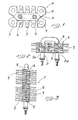
- Figure 1 is a cross-sectional view illustrating the subject heat exchanger and specifically showing the configuration of a modular element;
- Figure 2 is a top plan view illustrating a possible embodiment of heat exchanger, provided with a U-shaped electric resistance;
- Figure 3 is a side elevation view of that same heat exchanger; and
- Figure 4 is a elevation view illustrating a heat exchanger provided with a substantially rectilinear electric resistance.
- With reference to the Figures, the assemblable modular element heat exchanger structure according to the invention, which is generally indicated at the
reference number 1, comprises a central heating element, which consists of anelectric resistance 2, of substantially U-shape, as is shown in Figures 1 to 3, or which, possibly, may consist of anelectric resistance 3 of substantially rectilinear shape and substantially rectangular cross-section. - More specifically, the two branches or
legs 2a of theelectric resistance 2 are housed inhollows 4 defined in thecentral portion 5 of amodular element 6 which, advantageously,has a substantially plate-like shape. - The
hollows 4 are so designed as to intimately contact theelectric resistance 2 so as to provide a very good conduction heat transmission. - The
modular elements 6 which, as mentioned, has a substantially plate-like shape, are adjoined to one another so as to define a modular element pack or set, to provide the heat exchanger with the desired size. - The
modular elements 6 may be made by molding and are preferably made of uminium or copper. - The
central portion 5, as it has been mentioned, has a substantially plate-like shape and, from its edges,fins 7 extend which have preferably a less thickness than that of thecentral portion 5, so as to define air gaps, spaced from one another, adapted for increasing the thermal exchange surface. - The
fins 7 are substantially coplanar with respect to the plate-like element 5. - The
fins 7 are advantageously provided with throughgoingholes 8, formed through an intermediate portion thereof, which holes act to provide respective passages for the thermal exchange air flow. - This airflow is further increased, to provide a turbulence effect, which remarkably improves the mentioned thermal exchange.
- As is shown in Figure 4, the heat exchanger is provided with a central heating element consisting of a rectilinear heating
electric resistance 3; in this case the modular element, also indicated at 6, is provided with a single central hollow housing the rectilinear electric resistance, which resistance is provided with endelectrical connection portions 10. - From the above disclosure it should be apparent that the invention fully achieves the intended objects.
- In particular it should be pointed out that a heat exchanger has been provided which may be easily made by simply locating in an adjoining relationship specifically shaped modular elements which, in addition to remarkably increasing the thermal exchange surface, also act to facilitate the thermal exchange air convection movements as well as air turbulence at the modular elements thereby preventing air from stagnating to thermally insulate the exchange elements.
- Another important aspect of the invention is that the heat exchanger may be made with any sizes and shapes starting from standardized modular elements which may be coupled in any desired number thereby providing desired size heat exchangers.
- In practicing the invention the used mate rials, provided that they are compatible to the intended use, as well as the size and specific shapes, may be any according to requirements.
Claims (8)
1. An assemblable modular element heat exchanger, characterized in that it comprises a central heating element housed in at least a hollow defined in the central portion of a plurality of adjoining modular elements, from said central portion a plurality of fins extending which are substantially coplanar to said central portion.
2. An assemblable modular element heat exchanger, according to the preceding claim, characterized in that said modular elements have a substantially plate-like shape.
3. An assemblable modular element heat exchanger, according to the preceding claims, characterized in that said fins are provided with throughgoing holes.
4. An assemblable modular element heat exchanger, according to one or more of the preceding claims, characterized in that said fins have a less thickness than that of said central portion so as to define, between the fins of adjoining modular elements, regions to be traversed by the thermal exchange air flow.
5. An assemblable modular element heat exchanger, according to one or more of the preceding claims, characterized in that the heating element consists of a substantially U-shaped electric resistance the legs of which are housed in two hollows defined in said central portion.
6. An assemblable modular element heat exchanger, according to one or more of the preceding claims, characterized in that the central heating element consists of a rectilinear electric resistance housed in a single hollow defined in the central portion.
7. An assemblable modular element heat exchanger, according to one or more of the preceding claims, characterized in that said hollow has a shape mating with the cross-section of the heating element contained therein, in order to intimately contact the central heating element surface.
8. An assemblable modular element heat exchanger, according to one or more of the preceding claims, and as substantially disclosed and illustrated for the intended objects.
Applications Claiming Priority (2)
| Application Number | Priority Date | Filing Date | Title |
|---|---|---|---|
| IT2183186U IT208574Z2 (en) | 1986-05-15 | 1986-05-15 | HEAT EXCHANGER STRUCTURE WITH MODULAR MODULAR ELEMENTS. |
| IT2183186U | 1986-05-15 |
Publications (1)
| Publication Number | Publication Date |
|---|---|
| EP0252019A1 true EP0252019A1 (en) | 1988-01-07 |
Family
ID=11187475
Family Applications (1)
| Application Number | Title | Priority Date | Filing Date |
|---|---|---|---|
| EP87830182A Withdrawn EP0252019A1 (en) | 1986-05-15 | 1987-05-14 | Assemblable modular element heat exchanger |
Country Status (2)
| Country | Link |
|---|---|
| EP (1) | EP0252019A1 (en) |
| IT (1) | IT208574Z2 (en) |
Cited By (2)
| Publication number | Priority date | Publication date | Assignee | Title |
|---|---|---|---|---|
| FR2660746A1 (en) * | 1990-04-10 | 1991-10-11 | Valeo | Tube heat exchanger for rapid de-icing of a windscreen, and its method of mounting |
| CN104270842A (en) * | 2014-09-15 | 2015-01-07 | 常州市耀华仪器有限公司 | U-shaped heating pipe |
Citations (8)
| Publication number | Priority date | Publication date | Assignee | Title |
|---|---|---|---|---|
| US2051930A (en) * | 1935-02-09 | 1936-08-25 | Young Radiator Co | Electric heating unit |
| US2216778A (en) * | 1937-07-23 | 1940-10-08 | Houdry Process Corp | Heat exchange member and method of making |
| FR958125A (en) * | 1950-03-03 | |||
| US2537984A (en) * | 1944-06-13 | 1951-01-16 | Foster Wheeler Corp | Heat exchange apparatus |
| CH414705A (en) * | 1964-10-15 | 1966-06-15 | Bbc Brown Boveri & Cie | Heat exchange element |
| US3550680A (en) * | 1969-03-24 | 1970-12-29 | Orbit Mfg Co Inc | Finned tube heat exchanger and method of making same |
| FR2348617A1 (en) * | 1976-04-15 | 1977-11-10 | Finimetal Sarl | Insulated resistance heating element - has resistance element in metal tube with transverse vanes linked via expansion accommodating pads |
| DE2643817A1 (en) * | 1976-09-29 | 1978-03-30 | Eichenauer Fa Fritz | Heating element for hair drier - has metal block with heating cartridges and metal bristles projecting into air flow |
-
1986
- 1986-05-15 IT IT2183186U patent/IT208574Z2/en active
-
1987
- 1987-05-14 EP EP87830182A patent/EP0252019A1/en not_active Withdrawn
Patent Citations (8)
| Publication number | Priority date | Publication date | Assignee | Title |
|---|---|---|---|---|
| FR958125A (en) * | 1950-03-03 | |||
| US2051930A (en) * | 1935-02-09 | 1936-08-25 | Young Radiator Co | Electric heating unit |
| US2216778A (en) * | 1937-07-23 | 1940-10-08 | Houdry Process Corp | Heat exchange member and method of making |
| US2537984A (en) * | 1944-06-13 | 1951-01-16 | Foster Wheeler Corp | Heat exchange apparatus |
| CH414705A (en) * | 1964-10-15 | 1966-06-15 | Bbc Brown Boveri & Cie | Heat exchange element |
| US3550680A (en) * | 1969-03-24 | 1970-12-29 | Orbit Mfg Co Inc | Finned tube heat exchanger and method of making same |
| FR2348617A1 (en) * | 1976-04-15 | 1977-11-10 | Finimetal Sarl | Insulated resistance heating element - has resistance element in metal tube with transverse vanes linked via expansion accommodating pads |
| DE2643817A1 (en) * | 1976-09-29 | 1978-03-30 | Eichenauer Fa Fritz | Heating element for hair drier - has metal block with heating cartridges and metal bristles projecting into air flow |
Cited By (2)
| Publication number | Priority date | Publication date | Assignee | Title |
|---|---|---|---|---|
| FR2660746A1 (en) * | 1990-04-10 | 1991-10-11 | Valeo | Tube heat exchanger for rapid de-icing of a windscreen, and its method of mounting |
| CN104270842A (en) * | 2014-09-15 | 2015-01-07 | 常州市耀华仪器有限公司 | U-shaped heating pipe |
Also Published As
| Publication number | Publication date |
|---|---|
| IT8621831V0 (en) | 1986-05-15 |
| IT208574Z2 (en) | 1988-05-28 |
Similar Documents
| Publication | Publication Date | Title |
|---|---|---|
| EP1231448B1 (en) | Heat exchanger | |
| US5052480A (en) | Pipe for coolant condenser | |
| KR900006245B1 (en) | Heat exchanger | |
| GB2027534A (en) | Thermo-electric heat exchangers | |
| US5848638A (en) | Finned tube heat exchanger | |
| EP0252019A1 (en) | Assemblable modular element heat exchanger | |
| JP2003161589A (en) | Air conditioning plate fin type heat exchanger | |
| US20050039899A1 (en) | Turbulator for heat exchanger | |
| US5642777A (en) | Fin tube heat exchanger | |
| US3106958A (en) | Heat exchanger | |
| US6883598B2 (en) | Cooling element for a heat exchanger | |
| JP2004153001A (en) | Cooling fin and boiling cooler using the same | |
| JPS61211697A (en) | Plate fin type heat exchanger | |
| CN213335670U (en) | Heat exchanger, refrigerating system and household electrical appliance | |
| JPS6347740Y2 (en) | ||
| CN221527469U (en) | Microchannel heat exchanger, heat pump refrigerating system and clothes dryer | |
| JP2001116488A (en) | Plate fin for air-conditioning heat exchanger | |
| JPH0639247Y2 (en) | Heat transfer tube | |
| CN218915529U (en) | Heat radiation structure and household appliance | |
| JPH0525175U (en) | Tube of heat exchanger for evaporator | |
| CN219610422U (en) | High-power phase-change radiator | |
| JPH0396258A (en) | Heat-pipe type cooler | |
| JPS6020094A (en) | Heat exchanger | |
| JPS6215667Y2 (en) | ||
| JPS6226703Y2 (en) |
Legal Events
| Date | Code | Title | Description |
|---|---|---|---|
| PUAI | Public reference made under article 153(3) epc to a published international application that has entered the european phase |
Free format text: ORIGINAL CODE: 0009012 |
|
| AK | Designated contracting states |
Kind code of ref document: A1 Designated state(s): AT BE CH DE ES FR GB GR LI NL SE |
|
| 17P | Request for examination filed |
Effective date: 19880622 |
|
| 17Q | First examination report despatched |
Effective date: 19891220 |
|
| STAA | Information on the status of an ep patent application or granted ep patent |
Free format text: STATUS: THE APPLICATION IS DEEMED TO BE WITHDRAWN |
|
| 18D | Application deemed to be withdrawn |
Effective date: 19910629 |