EP0251720B1 - Prosthetic shape sensor - Google Patents
Prosthetic shape sensor Download PDFInfo
- Publication number
- EP0251720B1 EP0251720B1 EP87305688A EP87305688A EP0251720B1 EP 0251720 B1 EP0251720 B1 EP 0251720B1 EP 87305688 A EP87305688 A EP 87305688A EP 87305688 A EP87305688 A EP 87305688A EP 0251720 B1 EP0251720 B1 EP 0251720B1
- Authority
- EP
- European Patent Office
- Prior art keywords
- stump
- shape sensor
- camera unit
- patient
- camera
- Prior art date
- Legal status (The legal status is an assumption and is not a legal conclusion. Google has not performed a legal analysis and makes no representation as to the accuracy of the status listed.)
- Expired
Links
Images


Classifications
-
- A—HUMAN NECESSITIES
- A61—MEDICAL OR VETERINARY SCIENCE; HYGIENE
- A61B—DIAGNOSIS; SURGERY; IDENTIFICATION
- A61B5/00—Measuring for diagnostic purposes; Identification of persons
- A61B5/0059—Measuring for diagnostic purposes; Identification of persons using light, e.g. diagnosis by transillumination, diascopy, fluorescence
- A61B5/0062—Arrangements for scanning
- A61B5/0064—Body surface scanning
-
- A—HUMAN NECESSITIES
- A61—MEDICAL OR VETERINARY SCIENCE; HYGIENE
- A61B—DIAGNOSIS; SURGERY; IDENTIFICATION
- A61B5/00—Measuring for diagnostic purposes; Identification of persons
- A61B5/103—Measuring devices for testing the shape, pattern, colour, size or movement of the body or parts thereof, for diagnostic purposes
- A61B5/107—Measuring physical dimensions, e.g. size of the entire body or parts thereof
- A61B5/1077—Measuring of profiles
-
- A—HUMAN NECESSITIES
- A61—MEDICAL OR VETERINARY SCIENCE; HYGIENE
- A61F—FILTERS IMPLANTABLE INTO BLOOD VESSELS; PROSTHESES; DEVICES PROVIDING PATENCY TO, OR PREVENTING COLLAPSING OF, TUBULAR STRUCTURES OF THE BODY, e.g. STENTS; ORTHOPAEDIC, NURSING OR CONTRACEPTIVE DEVICES; FOMENTATION; TREATMENT OR PROTECTION OF EYES OR EARS; BANDAGES, DRESSINGS OR ABSORBENT PADS; FIRST-AID KITS
- A61F2/00—Filters implantable into blood vessels; Prostheses, i.e. artificial substitutes or replacements for parts of the body; Appliances for connecting them with the body; Devices providing patency to, or preventing collapsing of, tubular structures of the body, e.g. stents
- A61F2/50—Prostheses not implantable in the body
- A61F2/5044—Designing or manufacturing processes
- A61F2/5046—Designing or manufacturing processes for designing or making customized prostheses, e.g. using templates, finite-element analysis or CAD-CAM techniques
-
- A—HUMAN NECESSITIES
- A61—MEDICAL OR VETERINARY SCIENCE; HYGIENE
- A61F—FILTERS IMPLANTABLE INTO BLOOD VESSELS; PROSTHESES; DEVICES PROVIDING PATENCY TO, OR PREVENTING COLLAPSING OF, TUBULAR STRUCTURES OF THE BODY, e.g. STENTS; ORTHOPAEDIC, NURSING OR CONTRACEPTIVE DEVICES; FOMENTATION; TREATMENT OR PROTECTION OF EYES OR EARS; BANDAGES, DRESSINGS OR ABSORBENT PADS; FIRST-AID KITS
- A61F2/00—Filters implantable into blood vessels; Prostheses, i.e. artificial substitutes or replacements for parts of the body; Appliances for connecting them with the body; Devices providing patency to, or preventing collapsing of, tubular structures of the body, e.g. stents
- A61F2/50—Prostheses not implantable in the body
- A61F2/78—Means for protecting prostheses or for attaching them to the body, e.g. bandages, harnesses, straps, or stockings for the limb stump
- A61F2/80—Sockets, e.g. of suction type
Definitions
- the present invention relates to a prosthetic sensor, in particular for sensing the shape of below-knee stumps as a preliminary to fabricating prostheses.
- a shape sensor is known in which a laser beam is directed through a cylindrical lens to form a line of light which is projected onto a stump. When viewed from the side, the line of light is seen to be curved, representing the shape of the stump. The laser line is rotated about the stump and nine cameras are used to record the shape of the line. This sensor is expensive to produce and is rather complicated and bulky.
- FR-A-2 161 189 It is furthermore known (FR-A-2 161 189) to use a camera unit including a light source and a reflecting surface arranged opposite one another, such that the camera can make a photographic or cinematographic record of a silhouette view of an object located in the space between said camera and said reflecting surface.
- the present invention aims to provide a shape sensor which is simple, relatively inexpensive and compact.
- a prosthetic shape sensor comprising a single camera unit and a reflecting surface mounted on a turntable and arranged opposite each other to define therebetween a space for a stump of a patient, the reflecting surface being shaped to fit between the stump and a leg of the patient, wherein the camera unit includes a light source and wherein the camera unit and the reflecting surface are rotatable together on the turntable through at least 180°, whereby the camera unit can collect a series of silhouette views of the stump upon rotation about the stump.
- the shape sensor comprises a single camera unit I and a reflecting surface 2.
- Unit I and surface 2 define between them a space 3 for the stump 4 of a patient.
- the camera unit I and surface 2 are mounted together on a turntable 5 which is fitted in a base 6.
- the turntable 5 can rotate through at least 180 about the stump 4.
- the patient can be supported by hip supports 7 and distal rest 13.
- FIG 2 In Figure 2 is seen camera 8 and a large, therefore fresnel, lens 9 which would be mounted on the front of the camera unit I. Assuming that the camera diaphragm is at the focal point of the lens 9, all rays transversing the measurement volume, that is stump 4, are parallel. It should be noted that this imaging system is particularly suited to a single camera line illuminated triangulation system, since image deviation across the camera is directly proportional to radius and no geometric corrections are called for in deriving a regular set of data on either axis.
- illumination for high contrast can be provided by introducing light along the camera axis via a half-silvered mirror 12.
- the surface 2 is retro-reflective, e.g. by being formed from "high gain sheeting" sold by 3M under code T 7610. This allows contrast ratios of 100:1 to be achieved and room lighting could be ignored altogether.
- simple edge detectors can measure distances along a video line (as in the Vicon system for example, manufactured by Oxford Metrics of Botley, Oxford), This results in low data rates and storage requirements.
- the screen 2 is thin and curved so as to fit between the knees with minimal interference to the patient's stance.
- the measurement volume in the space 3 would not be more than 200 mm in diameter by 500 mm in height.
- this shape does not match the standard video format of 4 by 3.
- the aspect ratio of the imaged shape can be changed by attaching an anamorphic lens to the camera.
- a single 500 mm high fresnel lens would be costly while reducing the resolving power. It is therefore proposed to use two fresnel lens 10 and II, one above the other as shown in Figures 4 and 5.
- the camera view is split along two paths by the use of mirrors, and the combined image is shown in Figure 5A. Alternatively two cameras can be used, keeping each optical system independent.
- the camera used could be either a solid state camera or a scanned tube camera.
- the camera unit can be rotated by hand, which would obviate fears of rogue motor driven devices damaging the stump. With proper support of the stump, it is envisaged that the patient could stand still for 5 seconds. This would allow time for two sweeps of 2 seconds each.
- the microprocessor receiving the data can compare the results and reject them if there was too great a discrepancy between each sweep.
- fresnel lenses tilting the fresnel lenses will not be satisfactory. They have no appreciable field of view and although they are primarily used to maintain the telecentric condition they do make some contribution to the overall imagery. The severe aberrations of an off axis fresnel will become apparent.
- the base 6 also allows the introduction of a foot and so that the sensor can be used to record shank shapes to define custom cosmeses, or to record the alignment of successful prostheses while they are worn and load bearing.
Landscapes
- Health & Medical Sciences (AREA)
- Life Sciences & Earth Sciences (AREA)
- Engineering & Computer Science (AREA)
- Public Health (AREA)
- Biomedical Technology (AREA)
- Heart & Thoracic Surgery (AREA)
- Animal Behavior & Ethology (AREA)
- General Health & Medical Sciences (AREA)
- Veterinary Medicine (AREA)
- Biophysics (AREA)
- Surgery (AREA)
- Molecular Biology (AREA)
- Oral & Maxillofacial Surgery (AREA)
- Medical Informatics (AREA)
- Pathology (AREA)
- Physics & Mathematics (AREA)
- Cardiology (AREA)
- Dentistry (AREA)
- Manufacturing & Machinery (AREA)
- Vascular Medicine (AREA)
- Transplantation (AREA)
- Nuclear Medicine, Radiotherapy & Molecular Imaging (AREA)
- Radiology & Medical Imaging (AREA)
- Length Measuring Devices By Optical Means (AREA)
- Prostheses (AREA)
Description
- The present invention relates to a prosthetic sensor, in particular for sensing the shape of below-knee stumps as a preliminary to fabricating prostheses. A shape sensor is known in which a laser beam is directed through a cylindrical lens to form a line of light which is projected onto a stump. When viewed from the side, the line of light is seen to be curved, representing the shape of the stump. The laser line is rotated about the stump and nine cameras are used to record the shape of the line. This sensor is expensive to produce and is rather complicated and bulky.
- It is furthermore known (FR-A-2 161 189) to use a camera unit including a light source and a reflecting surface arranged opposite one another, such that the camera can make a photographic or cinematographic record of a silhouette view of an object located in the space between said camera and said reflecting surface.
- The present invention aims to provide a shape sensor which is simple, relatively inexpensive and compact.
- According to the invention there is provided a prosthetic shape sensor comprising a single camera unit and a reflecting surface mounted on a turntable and arranged opposite each other to define therebetween a space for a stump of a patient, the reflecting surface being shaped to fit between the stump and a leg of the patient, wherein the camera unit includes a light source and wherein the camera unit and the reflecting surface are rotatable together on the turntable through at least 180°, whereby the camera unit can collect a series of silhouette views of the stump upon rotation about the stump.
- As the unit is rotated a series of clear silhouette views is obtained with no interference from the other leg. From these tangential measures a number of horizontal cross-sections may be calculated to record the stump shape.
- Preferred embodiments of the invention are described in detail below, by example only, with reference to the accompanying drawings, wherein:
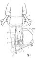
- Figure 1 is perspective view showing the shape sensor, with a patient standing in the space; and
- Figures 2, 3, 4, 5 and 6 are views showing possible camera and lens configurations.
- As shown in Figure I, the shape sensor comprises a single camera unit I and a reflecting
surface 2. Unit I and surface 2 define between them aspace 3 for the stump 4 of a patient. The camera unit I and surface 2 are mounted together on aturntable 5 which is fitted in abase 6. Theturntable 5 can rotate through at least 180 about the stump 4. - As illustrated, the patient can be supported by hip supports 7 and
distal rest 13. - In Figure 2 is seen
camera 8 and a large, therefore fresnel,lens 9 which would be mounted on the front of the camera unit I. Assuming that the camera diaphragm is at the focal point of thelens 9, all rays transversing the measurement volume, that is stump 4, are parallel. It should be noted that this imaging system is particularly suited to a single camera line illuminated triangulation system, since image deviation across the camera is directly proportional to radius and no geometric corrections are called for in deriving a regular set of data on either axis. - As shown in Figure 3 illumination for high contrast can be provided by introducing light along the camera axis via a half-silvered
mirror 12. Preferably, thesurface 2 is retro-reflective, e.g. by being formed from "high gain sheeting" sold by 3M under code T 7610. This allows contrast ratios of 100:1 to be achieved and room lighting could be ignored altogether. With good contrast, simple edge detectors can measure distances along a video line (as in the Vicon system for example, manufactured by Oxford Metrics of Botley, Oxford), This results in low data rates and storage requirements. Thescreen 2 is thin and curved so as to fit between the knees with minimal interference to the patient's stance. - In practice, it is expected that the measurement volume in the
space 3 would not be more than 200 mm in diameter by 500 mm in height. However, this shape does not match the standard video format of 4 by 3. The aspect ratio of the imaged shape can be changed by attaching an anamorphic lens to the camera. However, a single 500 mm high fresnel lens would be costly while reducing the resolving power. It is therefore proposed to use twofresnel lens 10 and II, one above the other as shown in Figures 4 and 5. The camera view is split along two paths by the use of mirrors, and the combined image is shown in Figure 5A. Alternatively two cameras can be used, keeping each optical system independent. - The camera used could be either a solid state camera or a scanned tube camera. The camera unit can be rotated by hand, which would obviate fears of rogue motor driven devices damaging the stump. With proper support of the stump, it is envisaged that the patient could stand still for 5 seconds. This would allow time for two sweeps of 2 seconds each. The microprocessor receiving the data can compare the results and reject them if there was too great a discrepancy between each sweep.
- Another embodiment will now be described which tackles the problem of "keystoning". At the objective lens, the two optical axes enter the lens off its own axis, as they must to split the fields. This results in a situation similar to that of an overhead projector whereby keystoning occurs.
- It is believed that tilting the fresnel lenses will not be satisfactory. They have no appreciable field of view and although they are primarily used to maintain the telecentric condition they do make some contribution to the overall imagery. The severe aberrations of an off axis fresnel will become apparent.
- However, it is not necessary to use a dual sensor to overcome this and a possible solution is shown in Figure 6. Mirror pairs MI, M3, and M2, M4 displace the two axes yet keep them parallel. Two objective lenses Li, L2 are now used and they form an intermediate image. This is demagnified onto the tube face- by a
relay lens 15. Afield lens 14 is used to maintain pupil imagery. - The above approach is advantageous for another reason. Splitting the field directly with mirrors leads to some overlap. The extent depends on the mirror size and lens aperture. For example if the mirrors were at the lens itself then there would be complete overlap, the two fields simply utilising different parts of the aperture.
- The
base 6 also allows the introduction of a foot and so that the sensor can be used to record shank shapes to define custom cosmeses, or to record the alignment of successful prostheses while they are worn and load bearing.
Claims (6)
Applications Claiming Priority (2)
| Application Number | Priority Date | Filing Date | Title |
|---|---|---|---|
| GB8615749 | 1986-06-27 | ||
| GB868615749A GB8615749D0 (en) | 1986-06-27 | 1986-06-27 | Shape sensor |
Publications (3)
| Publication Number | Publication Date |
|---|---|
| EP0251720A2 EP0251720A2 (en) | 1988-01-07 |
| EP0251720A3 EP0251720A3 (en) | 1988-11-17 |
| EP0251720B1 true EP0251720B1 (en) | 1991-05-02 |
Family
ID=10600207
Family Applications (1)
| Application Number | Title | Priority Date | Filing Date |
|---|---|---|---|
| EP87305688A Expired EP0251720B1 (en) | 1986-06-27 | 1987-06-25 | Prosthetic shape sensor |
Country Status (5)
| Country | Link |
|---|---|
| US (1) | US4819660A (en) |
| EP (1) | EP0251720B1 (en) |
| DE (1) | DE3769709D1 (en) |
| ES (1) | ES2022354B3 (en) |
| GB (2) | GB8615749D0 (en) |
Families Citing this family (20)
| Publication number | Priority date | Publication date | Assignee | Title |
|---|---|---|---|---|
| AT393954B (en) * | 1990-02-28 | 1992-01-10 | Bock Orthopaed Ind | METHOD AND DEVICE FOR DETERMINING THE USE PROPERTIES OF A PROSTHETIC PROPERTY |
| GB9021642D0 (en) * | 1990-10-05 | 1990-11-21 | Blatchford & Sons Ltd | Apparatus and method for use in the manufacture of a lower limb prosthesis |
| DE69023009T2 (en) * | 1990-10-31 | 1996-06-13 | Clynch Technologies Inc | METHOD AND ARRANGEMENT FOR DIGITIZING BY A LASER FOR PRODUCING PROSTHESES. |
| US5253656A (en) * | 1991-05-23 | 1993-10-19 | Rincoe Richard G | Apparatus and method for monitoring contact pressure between body parts and contact surfaces |
| DE4328380C1 (en) * | 1993-08-24 | 1995-04-13 | Lauth Klaus | Method for producing and / or correcting the dimensions of auxiliary parts adapted to areas of a living body and measuring device for carrying out the method |
| DE4401036C2 (en) * | 1994-01-15 | 2000-04-06 | Bock Orthopaed Ind | Display system for measuring the human body |
| US5522402A (en) * | 1994-05-13 | 1996-06-04 | Cooley; Robert A. | Three-dimensional scanning method for design of protheses |
| DE4417872A1 (en) * | 1994-05-22 | 1995-11-23 | Robert Prof Dr Ing Massen | Optical digitization of body parts |
| CA2304978C (en) | 2000-04-13 | 2008-02-12 | Giuceppe Milioto | Limb extremity positioning device and measurement method |
| DE10049926A1 (en) * | 2000-10-07 | 2002-04-11 | Robert Massen | Camera for photogrammetric detection of shape of limb has projector attachment for providing visually detectable alignment structures |
| US7113217B2 (en) * | 2001-07-13 | 2006-09-26 | Xenogen Corporation | Multi-view imaging apparatus |
| US7447558B2 (en) * | 2004-09-18 | 2008-11-04 | The Ohio Willow Wood Company | Apparatus for determining a three dimensional shape of an object |
| DE102006021788A1 (en) * | 2006-05-09 | 2007-11-22 | Otto Bock Healthcare Ip Gmbh & Co. Kg | A display system and method for displaying ground reaction forces on a human body |
| JP2010518385A (en) * | 2007-02-09 | 2010-05-27 | テーツェット テヒニク アクチエンゲゼルシャフト | Measuring device and method for determining geometrical properties of contours |
| CN101971189A (en) * | 2007-11-07 | 2011-02-09 | 爱墨菲特有限公司 | Impression foam digital scanner |
| US9924891B2 (en) * | 2012-10-04 | 2018-03-27 | Townsend Industries, Inc. | Method of preparing an image for use in production of a knee brace and a tibial contour gauge and an image alignment guide for use in said method |
| US20140276094A1 (en) * | 2013-03-15 | 2014-09-18 | Roy Herman Lidtke | Apparatus for optical scanning of the foot for orthosis |
| WO2018011331A1 (en) * | 2016-07-13 | 2018-01-18 | Naked Labs Austria Gmbh | Motor driven turntable with foldable sensor mast |
| US10874539B2 (en) | 2017-05-05 | 2020-12-29 | Becker Orthopedic Appliance Company | Configurable orthosis and method of definitive orthotic design, fabrication and validation |
| RU2768576C1 (en) * | 2021-04-07 | 2022-03-24 | Денис Рустамович Хашев | Automated patient's stump analysis device |
Family Cites Families (15)
| Publication number | Priority date | Publication date | Assignee | Title |
|---|---|---|---|---|
| FR1564781A (en) * | 1968-03-01 | 1969-04-25 | ||
| NL7016262A (en) * | 1970-11-06 | 1972-05-09 | ||
| FR2161189A5 (en) * | 1971-11-17 | 1973-07-06 | Boixel Emile | |
| US4062355A (en) * | 1976-04-09 | 1977-12-13 | Joshua Morley Kaye | Device for use in evaluating the lower leg and foot |
| GB1539882A (en) * | 1976-05-19 | 1979-02-07 | Secretary Industry Brit | Contour mapping of the surface of an object |
| FR2491323A1 (en) * | 1980-10-03 | 1982-04-09 | Boixel Emile | Device for recording shape and size of human body - comprises camera with annular light source directing light at subject standing in front of self-collimating screen |
| SU923522A1 (en) * | 1980-10-15 | 1982-04-30 | Московский Ордена Трудового Красного Знамени Научно-Исследовательский Рентгено-Радиологический Институт | Device for drawing body contour |
| US4662079A (en) * | 1983-05-10 | 1987-05-05 | Graf Peter M | Process and apparatus for forming customized footwear |
| IT1163495B (en) * | 1983-06-10 | 1987-04-08 | Fondazione Pro Juventute Don C | EQUIPMENT FOR THE CLINICAL DOCUMENTATION OF POSTURAL VICES AND FOR THE QUANTIFICATION OF THE LOADS ON THE BODY SEGMENTS IN STATIC AND DYNAMIC CONDITIONS |
| JPS60142838A (en) * | 1983-10-28 | 1985-07-29 | 吉澤 徹 | Method and apparatus for diagnosis of spine disease |
| DE3443512A1 (en) * | 1984-04-06 | 1985-10-17 | GGT-Medizin-Electronic-Systeme GmbH, 8000 München | METHOD AND DEVICE FOR DETERMINING AND IMPROVING THE OPERATIONAL FUNCTION OF THE MOVEMENT APPARATUS OF MAN |
| FR2565481B1 (en) * | 1984-06-06 | 1988-11-18 | Oreal | PROCESS FOR ASSESSING VARIATIONS, OVER TIME, IN THE CHARACTERISTICS OF A ZONE OR OF AN ENTIRE PERSON, INSTALLATION FOR IMPLEMENTING THE METHOD AND APPLICATIONS OF SUCH A PROCESS |
| US4604807A (en) * | 1984-12-21 | 1986-08-12 | Interco, Incorporated | Electronic foot measuring apparatus and method |
| US4538353A (en) * | 1984-12-21 | 1985-09-03 | Interco, Incorporated | Electronic foot measuring apparatus and method |
| SE469321B (en) * | 1986-04-14 | 1993-06-21 | Joenkoepings Laens Landsting | SET AND DEVICE TO MAKE A MODIFIED THREE-DIMENSIONAL IMAGE OF AN ELASTIC DEFORMABLE PURPOSE |
-
1986
- 1986-06-27 GB GB868615749A patent/GB8615749D0/en active Pending
-
1987
- 1987-06-23 US US07/065,406 patent/US4819660A/en not_active Expired - Fee Related
- 1987-06-25 ES ES87305688T patent/ES2022354B3/en not_active Expired - Lifetime
- 1987-06-25 GB GB8714879A patent/GB2193805B/en not_active Expired - Lifetime
- 1987-06-25 DE DE8787305688T patent/DE3769709D1/en not_active Expired - Lifetime
- 1987-06-25 EP EP87305688A patent/EP0251720B1/en not_active Expired
Also Published As
| Publication number | Publication date |
|---|---|
| GB8714879D0 (en) | 1987-07-29 |
| GB2193805A (en) | 1988-02-17 |
| US4819660A (en) | 1989-04-11 |
| GB8615749D0 (en) | 1986-08-06 |
| EP0251720A2 (en) | 1988-01-07 |
| GB2193805B (en) | 1990-01-31 |
| EP0251720A3 (en) | 1988-11-17 |
| DE3769709D1 (en) | 1991-06-06 |
| ES2022354B3 (en) | 1991-12-01 |
Similar Documents
| Publication | Publication Date | Title |
|---|---|---|
| US4819660A (en) | Prosthetic shape sensor | |
| US4805638A (en) | Apparatus for photogrammetrically measuring the human head | |
| US5291234A (en) | Auto optical focus detecting device and eye direction detecting optical system | |
| JP3159477B2 (en) | Ophthalmic equipment | |
| EP0836830B1 (en) | Ophthalmic refraction measurement apparatus | |
| JPH10500033A (en) | Apparatus and method for mapping objects | |
| EP0354002B1 (en) | Optical alignment system for an ophthalmic instrument | |
| US5909268A (en) | Alignment detecting apparatus | |
| US5903782A (en) | Method and apparatus for producing a three-hundred and sixty degree spherical visual data set | |
| CA2211622A1 (en) | Stereomicroscope | |
| EP0305107A2 (en) | Three-dimensional scanner | |
| WO1995016386B1 (en) | Eye fundus optical scanner system and method | |
| JPH0359689B2 (en) | ||
| BR9408338A (en) | Equipment for examining the fundus of an eye and for detecting an ocular light pattern reflected by the fund Equipment for positionalizing the fundus of an eye for examination and detection of an ocular light pattern reflected by the fund visual axis method for positioning the bottom of an eye having a visual axis for examination by a radiation beam using equipment to focus an image of an object through a lens on a focal plane having the | |
| US6304723B1 (en) | Retinal camera | |
| JP2706246B2 (en) | Ophthalmic equipment | |
| JPH0984760A (en) | Alignment detector for ophthalmic instruments | |
| JP3423447B2 (en) | Fundus camera | |
| JP3109870B2 (en) | Video camera | |
| JPH10341373A (en) | Image-pickup device | |
| JPH04174639A (en) | corneal curvature measuring device | |
| JP2925165B2 (en) | Autofocus fundus camera | |
| JP2693772B2 (en) | Ophthalmic equipment | |
| JPH02161Y2 (en) | ||
| JPH0567281B2 (en) |
Legal Events
| Date | Code | Title | Description |
|---|---|---|---|
| PUAI | Public reference made under article 153(3) epc to a published international application that has entered the european phase |
Free format text: ORIGINAL CODE: 0009012 |
|
| AK | Designated contracting states |
Kind code of ref document: A2 Designated state(s): AT BE CH DE ES FR GB GR IT LI LU NL SE |
|
| RBV | Designated contracting states (corrected) |
Designated state(s): BE CH DE ES FR GB IT LI NL SE |
|
| PUAL | Search report despatched |
Free format text: ORIGINAL CODE: 0009013 |
|
| RHK1 | Main classification (correction) |
Ipc: A61F 2/76 |
|
| AK | Designated contracting states |
Kind code of ref document: A3 Designated state(s): BE CH DE ES FR GB IT LI NL SE |
|
| 17P | Request for examination filed |
Effective date: 19881213 |
|
| 17Q | First examination report despatched |
Effective date: 19900628 |
|
| GRAA | (expected) grant |
Free format text: ORIGINAL CODE: 0009210 |
|
| AK | Designated contracting states |
Kind code of ref document: B1 Designated state(s): BE CH DE ES FR GB IT LI NL SE |
|
| REF | Corresponds to: |
Ref document number: 3769709 Country of ref document: DE Date of ref document: 19910606 |
|
| RAP2 | Party data changed (patent owner data changed or rights of a patent transferred) |
Owner name: THE SECRETARY OF STATE FOR HEALTH |
|
| REG | Reference to a national code |
Ref country code: CH Ref legal event code: PUE Owner name: THE SECRETARY OF STATE FOR HEALTH |
|
| ITF | It: translation for a ep patent filed | ||
| ET | Fr: translation filed | ||
| NLT2 | Nl: modifications (of names), taken from the european patent patent bulletin |
Owner name: THE SECRETARY OF STATE FOR HEALTH TE LONDEN, GROOT |
|
| NLXE | Nl: other communications concerning ep-patents (part 3 heading xe) |
Free format text: IN PAT.BUL.16/91,PAGES 2153 AND 2224:CORR.:THE SECRETARY OF STATE FOR HEALTH PAT.BUL.16/91,PAGE 2235,SHOULD BE DELETED |
|
| PLBE | No opposition filed within time limit |
Free format text: ORIGINAL CODE: 0009261 |
|
| STAA | Information on the status of an ep patent application or granted ep patent |
Free format text: STATUS: NO OPPOSITION FILED WITHIN TIME LIMIT |
|
| 26N | No opposition filed | ||
| EAL | Se: european patent in force in sweden |
Ref document number: 87305688.1 |
|
| PGFP | Annual fee paid to national office [announced via postgrant information from national office to epo] |
Ref country code: FR Payment date: 19950609 Year of fee payment: 9 |
|
| PGFP | Annual fee paid to national office [announced via postgrant information from national office to epo] |
Ref country code: GB Payment date: 19950614 Year of fee payment: 9 |
|
| PGFP | Annual fee paid to national office [announced via postgrant information from national office to epo] |
Ref country code: SE Payment date: 19950615 Year of fee payment: 9 |
|
| PGFP | Annual fee paid to national office [announced via postgrant information from national office to epo] |
Ref country code: DE Payment date: 19950617 Year of fee payment: 9 |
|
| PGFP | Annual fee paid to national office [announced via postgrant information from national office to epo] |
Ref country code: CH Payment date: 19950623 Year of fee payment: 9 |
|
| PGFP | Annual fee paid to national office [announced via postgrant information from national office to epo] |
Ref country code: NL Payment date: 19950628 Year of fee payment: 9 Ref country code: ES Payment date: 19950628 Year of fee payment: 9 |
|
| PGFP | Annual fee paid to national office [announced via postgrant information from national office to epo] |
Ref country code: BE Payment date: 19950809 Year of fee payment: 9 |
|
| PG25 | Lapsed in a contracting state [announced via postgrant information from national office to epo] |
Ref country code: GB Effective date: 19960625 |
|
| PG25 | Lapsed in a contracting state [announced via postgrant information from national office to epo] |
Ref country code: SE Effective date: 19960626 Ref country code: ES Free format text: LAPSE BECAUSE OF THE APPLICANT RENOUNCES Effective date: 19960626 |
|
| PG25 | Lapsed in a contracting state [announced via postgrant information from national office to epo] |
Ref country code: LI Effective date: 19960630 Ref country code: CH Effective date: 19960630 Ref country code: BE Effective date: 19960630 |
|
| BERE | Be: lapsed |
Owner name: THE SECRETARY OF STATE FOR HEALTH Effective date: 19960630 |
|
| PG25 | Lapsed in a contracting state [announced via postgrant information from national office to epo] |
Ref country code: NL Effective date: 19970101 |
|
| GBPC | Gb: european patent ceased through non-payment of renewal fee |
Effective date: 19960625 |
|
| REG | Reference to a national code |
Ref country code: CH Ref legal event code: PL |
|
| PG25 | Lapsed in a contracting state [announced via postgrant information from national office to epo] |
Ref country code: FR Effective date: 19970228 |
|
| PG25 | Lapsed in a contracting state [announced via postgrant information from national office to epo] |
Ref country code: DE Effective date: 19970301 |
|
| EUG | Se: european patent has lapsed |
Ref document number: 87305688.1 |
|
| NLV4 | Nl: lapsed or anulled due to non-payment of the annual fee |
Effective date: 19970101 |
|
| REG | Reference to a national code |
Ref country code: FR Ref legal event code: ST |
|
| REG | Reference to a national code |
Ref country code: ES Ref legal event code: FD2A Effective date: 19991007 |
|
| PG25 | Lapsed in a contracting state [announced via postgrant information from national office to epo] |
Ref country code: IT Free format text: LAPSE BECAUSE OF NON-PAYMENT OF DUE FEES;WARNING: LAPSES OF ITALIAN PATENTS WITH EFFECTIVE DATE BEFORE 2007 MAY HAVE OCCURRED AT ANY TIME BEFORE 2007. THE CORRECT EFFECTIVE DATE MAY BE DIFFERENT FROM THE ONE RECORDED. Effective date: 20050625 |