EP0251663B1 - Connector - Google Patents
Connector Download PDFInfo
- Publication number
- EP0251663B1 EP0251663B1 EP19870305594 EP87305594A EP0251663B1 EP 0251663 B1 EP0251663 B1 EP 0251663B1 EP 19870305594 EP19870305594 EP 19870305594 EP 87305594 A EP87305594 A EP 87305594A EP 0251663 B1 EP0251663 B1 EP 0251663B1
- Authority
- EP
- European Patent Office
- Prior art keywords
- container
- component
- dispenser
- neck
- ring
- Prior art date
- Legal status (The legal status is an assumption and is not a legal conclusion. Google has not performed a legal analysis and makes no representation as to the accuracy of the status listed.)
- Expired - Lifetime
Links
- 230000015572 biosynthetic process Effects 0.000 claims description 18
- 238000005755 formation reaction Methods 0.000 claims description 18
- 239000012530 fluid Substances 0.000 claims description 7
- 239000000463 material Substances 0.000 claims description 5
- 229920003023 plastic Polymers 0.000 claims description 4
- 239000004033 plastic Substances 0.000 claims description 4
- 238000000926 separation method Methods 0.000 claims description 2
- GHXZTYHSJHQHIJ-UHFFFAOYSA-N Chlorhexidine Chemical class C=1C=C(Cl)C=CC=1NC(N)=NC(N)=NCCCCCCN=C(N)N=C(N)NC1=CC=C(Cl)C=C1 GHXZTYHSJHQHIJ-UHFFFAOYSA-N 0.000 description 5
- 238000009472 formulation Methods 0.000 description 4
- 238000007373 indentation Methods 0.000 description 4
- 239000000203 mixture Substances 0.000 description 4
- 239000007788 liquid Substances 0.000 description 3
- 238000000034 method Methods 0.000 description 3
- 230000002421 anti-septic effect Effects 0.000 description 2
- 229940064004 antiseptic throat preparations Drugs 0.000 description 2
- -1 aromatic alcohols Chemical class 0.000 description 2
- 239000011324 bead Substances 0.000 description 2
- 239000006260 foam Substances 0.000 description 2
- 210000003141 lower extremity Anatomy 0.000 description 2
- 239000000126 substance Substances 0.000 description 2
- 239000004094 surface-active agent Substances 0.000 description 2
- 230000001476 alcoholic effect Effects 0.000 description 1
- 239000003242 anti bacterial agent Substances 0.000 description 1
- 229940088710 antibiotic agent Drugs 0.000 description 1
- 229960003333 chlorhexidine gluconate Drugs 0.000 description 1
- YZIYKJHYYHPJIB-UUPCJSQJSA-N chlorhexidine gluconate Chemical compound OC[C@@H](O)[C@@H](O)[C@H](O)[C@@H](O)C(O)=O.OC[C@@H](O)[C@@H](O)[C@H](O)[C@@H](O)C(O)=O.C1=CC(Cl)=CC=C1NC(=N)NC(=N)NCCCCCCNC(=N)NC(=N)NC1=CC=C(Cl)C=C1 YZIYKJHYYHPJIB-UUPCJSQJSA-N 0.000 description 1
- 230000001419 dependent effect Effects 0.000 description 1
- 238000007599 discharging Methods 0.000 description 1
- 230000009977 dual effect Effects 0.000 description 1
- 239000007789 gas Substances 0.000 description 1
- 239000004615 ingredient Substances 0.000 description 1
- 230000003993 interaction Effects 0.000 description 1
- 239000008267 milk Substances 0.000 description 1
- 210000004080 milk Anatomy 0.000 description 1
- 235000013336 milk Nutrition 0.000 description 1
- 238000000465 moulding Methods 0.000 description 1
- 239000003973 paint Substances 0.000 description 1
- 239000000843 powder Substances 0.000 description 1
- 239000007921 spray Substances 0.000 description 1
Images
Classifications
-
- B—PERFORMING OPERATIONS; TRANSPORTING
- B65—CONVEYING; PACKING; STORING; HANDLING THIN OR FILAMENTARY MATERIAL
- B65D—CONTAINERS FOR STORAGE OR TRANSPORT OF ARTICLES OR MATERIALS, e.g. BAGS, BARRELS, BOTTLES, BOXES, CANS, CARTONS, CRATES, DRUMS, JARS, TANKS, HOPPERS, FORWARDING CONTAINERS; ACCESSORIES, CLOSURES, OR FITTINGS THEREFOR; PACKAGING ELEMENTS; PACKAGES
- B65D49/00—Arrangements or devices for preventing refilling of containers
-
- B—PERFORMING OPERATIONS; TRANSPORTING
- B65—CONVEYING; PACKING; STORING; HANDLING THIN OR FILAMENTARY MATERIAL
- B65D—CONTAINERS FOR STORAGE OR TRANSPORT OF ARTICLES OR MATERIALS, e.g. BAGS, BARRELS, BOTTLES, BOXES, CANS, CARTONS, CRATES, DRUMS, JARS, TANKS, HOPPERS, FORWARDING CONTAINERS; ACCESSORIES, CLOSURES, OR FITTINGS THEREFOR; PACKAGING ELEMENTS; PACKAGES
- B65D55/00—Accessories for container closures not otherwise provided for
- B65D55/02—Locking devices; Means for discouraging or indicating unauthorised opening or removal of closure
-
- B—PERFORMING OPERATIONS; TRANSPORTING
- B65—CONVEYING; PACKING; STORING; HANDLING THIN OR FILAMENTARY MATERIAL
- B65D—CONTAINERS FOR STORAGE OR TRANSPORT OF ARTICLES OR MATERIALS, e.g. BAGS, BARRELS, BOTTLES, BOXES, CANS, CARTONS, CRATES, DRUMS, JARS, TANKS, HOPPERS, FORWARDING CONTAINERS; ACCESSORIES, CLOSURES, OR FITTINGS THEREFOR; PACKAGING ELEMENTS; PACKAGES
- B65D25/00—Details of other kinds or types of rigid or semi-rigid containers
- B65D25/38—Devices for discharging contents
- B65D25/40—Nozzles or spouts
- B65D25/48—Separable nozzles or spouts
- B65D25/50—Separable nozzles or spouts arranged to be plugged in two alternate positions
-
- B—PERFORMING OPERATIONS; TRANSPORTING
- B65—CONVEYING; PACKING; STORING; HANDLING THIN OR FILAMENTARY MATERIAL
- B65D—CONTAINERS FOR STORAGE OR TRANSPORT OF ARTICLES OR MATERIALS, e.g. BAGS, BARRELS, BOTTLES, BOXES, CANS, CARTONS, CRATES, DRUMS, JARS, TANKS, HOPPERS, FORWARDING CONTAINERS; ACCESSORIES, CLOSURES, OR FITTINGS THEREFOR; PACKAGING ELEMENTS; PACKAGES
- B65D47/00—Closures with filling and discharging, or with discharging, devices
- B65D47/04—Closures with discharging devices other than pumps
- B65D47/06—Closures with discharging devices other than pumps with pouring spouts or tubes; with discharge nozzles or passages
-
- Y—GENERAL TAGGING OF NEW TECHNOLOGICAL DEVELOPMENTS; GENERAL TAGGING OF CROSS-SECTIONAL TECHNOLOGIES SPANNING OVER SEVERAL SECTIONS OF THE IPC; TECHNICAL SUBJECTS COVERED BY FORMER USPC CROSS-REFERENCE ART COLLECTIONS [XRACs] AND DIGESTS
- Y02—TECHNOLOGIES OR APPLICATIONS FOR MITIGATION OR ADAPTATION AGAINST CLIMATE CHANGE
- Y02W—CLIMATE CHANGE MITIGATION TECHNOLOGIES RELATED TO WASTEWATER TREATMENT OR WASTE MANAGEMENT
- Y02W30/00—Technologies for solid waste management
- Y02W30/50—Reuse, recycling or recovery technologies
- Y02W30/80—Packaging reuse or recycling, e.g. of multilayer packaging
-
- Y—GENERAL TAGGING OF NEW TECHNOLOGICAL DEVELOPMENTS; GENERAL TAGGING OF CROSS-SECTIONAL TECHNOLOGIES SPANNING OVER SEVERAL SECTIONS OF THE IPC; TECHNICAL SUBJECTS COVERED BY FORMER USPC CROSS-REFERENCE ART COLLECTIONS [XRACs] AND DIGESTS
- Y10—TECHNICAL SUBJECTS COVERED BY FORMER USPC
- Y10T—TECHNICAL SUBJECTS COVERED BY FORMER US CLASSIFICATION
- Y10T403/00—Joints and connections
- Y10T403/70—Interfitted members
- Y10T403/7009—Rotary binding cam or wedge
- Y10T403/7011—Radially interposed shim or bushing
Definitions
- connection devices more particularly devices for providing a connection between a container and a means for dispensing the contents of the container.
- inlet and outlet refer to an inlet for fluid and an outlet for fluid respectively.
- Fluid means liquid, gas or powder but most particularly means liquid. It will be understood that the terms inlet and outlet may be interchangeable in that upon reversal of fluid flow an inlet may become an outlet and vice versa.
- the invention provides a component having an inlet portion provided with a member moveable between at least two positions being (i) a first position permitting engagement with means for supporting the component in connection with a second component having an outlet portion and (ii) a second position not permitting re-engagement, the arrangement being such that the member cannot readily be moved from the second position to the first position and that the member moves between the first and second position upon either connection or disconnection of the component and the second component.
- the invention provides a component having an outlet portion provided with means adapted to support a component having an inlet portion as hereinbefore described and not to permit separation of the components when the member is in the first position and which does not permit reconnection of the components when the member is in the second position.
- the invention provides an assembly comprising a component having an inlet portion of the type described and a component having an outlet portion of the type described for use in transferring fluid from the inlet portion to the outlet portion.
- the invention is particularly useful for providing an improved connection between a container and a dispenser such that upon removal of the container from connection with the dispenser the container cannot be reconnected thereto.
- the invention provides, in a particular aspect, a container provided with a member moveable between at least two positions being a first position permitting engagement with means for supporting the container in connection with apparatus for dispensing the contents of the container and a second position not permitting re-engagement, the arrangement being such that the member cannot readily be moved from the second position to the first position and that the member moves between the first and second position upon either connection or disconnection of the container and the apparatus.
- the invention provides a dispenser provided with means adapted to support a container as hereinbefore described and not to permit removal of the container therefrom when the member is in the first position and which does not permit reconnection of the container and dispenser when the member is in the second position.
- the invention provides an assembly comprising a container and a dispenser of the types hereinbefore described for use in dispensing the contents of the container.
- the container may be provided in the form of a bottle which may be of any shape, but which will conveniently be provided with a neck which will conveniently be at least in part of substantially circular cross-section.
- the member referred to is conveniently provided in the form of a collar eg. a ring slideably moveable on the neck, the first and second positions of the ring on the neck being defined by formations on the neck.
- the member could also be non-circular and adapted to be slideably moveable on a neck of corresponding non-circular cross-section.
- the container (including the neck) may advantageously be manufactured from plastics material and the said formations on the neck may take the form of mouldings thereon.
- the member is provided in the form of a ring which may be manufactured from plastics material.
- the said ring may initially be applied to the neck as part of a closure for the container, which may be of the type known as a "tamper-evident" closure.
- closures comprise a cap portion comprising a top and depending skirt and a ring portion which depends from the lower edge of the skirt of the cap by frangible connecting pieces such that when the closure is first applied to the neck the cap and ring portions are secured in position for example by interengaging threaded portions on the cap portion and the neck but upon removal of the cap the frangible connecting pieces between the cap and ring portion break leaving the ring in place.
- the cap and ring portions are normally moulded in one piece from plastics material.
- a further advantage can be gained by providing the ring with formations adapted to engage with discontinuous ratchet shaped outer beads on the neck such that the formations on the ring ride over the ratchets on the neck when the cap is screwed on and engage so as to prevent rotation of the ring when the cap is unscrewed.
- the formations may be discontinuous ratchet shaped inner beads as shown in published European Patent Application No. 133348.
- a still further advantage can be gained by providing the upper surface of the ring with ratchet shaped formations adapted to engage with corresponding ratchet shaped formations on the lower surface of a formation on the neck defining the first position for the ring.
- the ring portion can thus serve the dual purpose of providing part of a tamper evident closure for a container and being the moveable member described above.
- the means for supporting the container may be provided in the form of one or more arms depending from the dispenser having formations adapted to engage with the member in its first position thus being able to provide support for the container, and adapted to permit disengagement of the container therefrom when the member is in its second position.
- the arm or arms may be adapted to release the container upon operation of a lever, button or switch, or (in a preferred embodiment) upon rotation of the container, conveniently a bottle, in one or either direction.
- the bottle for example may be provided with formations adapted to force apart the .arms and thus release the bottle upon rotation thereof.
- Such formations may be provided on the neck or on the bottle itself.
- the dispenser may be any means for discharging the contents of the container, for example a pump, spray jet or nozzle, tap or measured quantity dispenser (eg as used for dispensing alcoholic liquors).
- a particular field in which the invention is useful is in the dispensing of surgical and general purpose hospital hand cleansing formulations which normally contain antiseptics.
- chlorhexidine salts eg chlorhexidine gluconate
- Imperial Chemical Industries PLC under the trade mark "Hibitane”.
- Formulations containing chlorhexidine salts together with surfactants and other ingredients are for example described in British Patent No. 1338003 and are sold by Imperial Chemical Industries PLC and its associated companies under the trade marks "Hibiscrub” and "Hibiciens". Such formulations may be provided in containers in accordance with the invention which may be used in assembly with known dispensers provided with support means in accordance with the invention.
- formulations containing chlorhexidine salts, aromatic alcohols and low levels (less than 10% by weight) of surfactants such as are described in our copending British Patent Application No 8607686 may be dispensed from containers in accordance with the invention which may advantageously be used in assembly with foam generating dispensers provided with support means in accordance with the invention.
- Suitable foam generating dispensers are described for example in published European Patent Applications Nos. 19582 and 79853.
- the invention may also be useful for providing a connection between inlet and outlet portions on any pair of components which require a non-reusable connection between them.
- the invention is primarily of use in the field of disposable equipment, in particular disposable hospital equipment, where it is desired that the equipment is only used once.
- the invention could provide a connection between tubes used for liquid transport.
- a particular use for the invention in this aspect would be for example in the connection of an outlet from a catheter to the inlet of a tube leading to a drainage bag, where it is desired to ensure that the drainage bag could not be reused or accidentally reconnected.
- a further application of the invention is in the field of non-reusable containers for fluids, such as for example, milk, paint, freeze-dried antibiotics and the like. Other applications for the invention will be evident to the reader of the specification and are included within the scope of the invention accordingly.
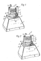
- the bottle indicated generally by (1) (which may be of any shape but is illustrated herein as having a squarish cross-section) is provided with a neck (2) with a threaded portion (3). Below the threaded portion are moulded formations (4) and (5) seen most clearly in Fig. 4.
- a ring (6) is disposed about the neck portion in such a way that in Fig. 1 it rests upon the upper surface of the moulded portion (5) (which is slightly concave in section) and abuts the lower (flat) surface of the moulded portion (4).
- the ring (6) is thus prevented from moving upward in relation to the neck as drawn but can move downward upon the application of sufficient force, the ring being desirably made in such a way that it deforms sufficiently to allow it to move down past the upper surface of the moulded portion (5), but resists upward movement past the moulded portion (4).
- the ring may be provided with internal projecting means adapted to position and engage below the flat lower surface of the moulded portion (4), as generally described in European Patent Application 80846.
- Three arms (7) extend downward from the dispenser (not shown) and are provided with indentations (8) which correspond in dimension with the depth of the ring (6) such that the arms in Fig. 1 grip the ring.
- the bottle (1) is thus supported by the arms via the ring as it abuts the lower surface of the moulded portion (4).
- the lower extremities (9) of the arms (7) do not come into contact with the cam surfaces (10) which are provided on the bottle about the lower part of the neck and thus rotation of the bottle simply causes the ring to rotate in relation to the arms (7) without releasing the bottle.
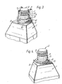
- the bottle (1) is provided with a projecting lug (12) and the dispenser (not shown) has a back-plate (13) provided with guiding means for said lug (12).
- Figure 5 shows a bottle (1) having a projecting lug (12)
- Figure 6 shows a back-plate (13) having a channel (14) formed between two raised portions (15a, 15b) in which channel the lug (12) is slideably movable.
- the bottle (1) is placed against the back-plate (13) with the lug (12) at the lower end of channel (14). Upward movement of the bottle (1) urges the lug (12) up the channel (14) to the top of said channel.
- bottle (1) is held by dependent arms of the dispenser, as described with regard to Figures 1 and 2.
- the bottle (1) is rotated in either direction so that the lug (12) is urged upwards by interaction with the guiding cam surfaces (16a, 16b).
- the bottle (1) is urged upwards and the necessary force is provided to move ring (6) over the moulded portion (5) as hereinbefore described.
- the movement of the ring (6) can be concurrent with the opening of the arms of the dispenser.
- the ring (6) Upon removal of the bottle the ring (6) falls from its previous position abutting the lower edge of the moulded portion (5) into the position shown in Fig. 4, in which the ring lies against the cam surfaces (10) on the top part of the bottle.
- the ring is advantageously made of a material, and with a configuration, making it difficult or impossible to return the ring from the position shown in Fig 4 to that shown in Fig 1 without breaking it. This purpose may for example be accomplished by making the ring in accordance with European Patent Applications 80846 and 133348, as discussed above.
- the ring may advantageously be applied to the bottle initially as part of a tamper resistant closure which is screwed onto the bottle neck in such a manner that the ring portion thereof slides over the upper surface of the moulded portion (4) into the position shown in Fig. 1 and is left in that position upon removal of the cap portion of the said closure.
- Application of the bottle to the dispenser will then result in the ring being in the position shown in Fig 1 in relation to the arms (7).
- Such a tamper resistant closure may be advantageously as described in European Patent Application 80846 and 133348, and/or the upper surface of the ring 6 may be provided with ratchet shaped formations adapted to engage with corresponding ratchet shaped formations on the lower surface of the moulded portion (4).
Landscapes
- Mechanical Engineering (AREA)
- Engineering & Computer Science (AREA)
- Closures For Containers (AREA)
- Mechanical Coupling Of Light Guides (AREA)
- Surgical Instruments (AREA)
- Coupling Device And Connection With Printed Circuit (AREA)
- Paper (AREA)
- Containers And Packaging Bodies Having A Special Means To Remove Contents (AREA)
- Fittings On The Vehicle Exterior For Carrying Loads, And Devices For Holding Or Mounting Articles (AREA)
- Non-Reversible Transmitting Devices (AREA)
- Electroluminescent Light Sources (AREA)
- Pens And Brushes (AREA)
- Saccharide Compounds (AREA)
- Physical Deposition Of Substances That Are Components Of Semiconductor Devices (AREA)
- Sink And Installation For Waste Water (AREA)
- Earth Drilling (AREA)
- Manufacturing Of Electric Cables (AREA)
- Connections Effected By Soldering, Adhesion, Or Permanent Deformation (AREA)
- Details Of Rigid Or Semi-Rigid Containers (AREA)
- Filling Of Jars Or Cans And Processes For Cleaning And Sealing Jars (AREA)
- Pressure Vessels And Lids Thereof (AREA)
- Stackable Containers (AREA)
- Connector Housings Or Holding Contact Members (AREA)
- Discharge Of Articles From Conveyors (AREA)
Priority Applications (1)
| Application Number | Priority Date | Filing Date | Title |
|---|---|---|---|
| AT87305594T ATE60559T1 (de) | 1986-06-24 | 1987-06-23 | Verbindungsvorrichtung. |
Applications Claiming Priority (2)
| Application Number | Priority Date | Filing Date | Title |
|---|---|---|---|
| GB8615410 | 1986-06-24 | ||
| GB8615410A GB8615410D0 (en) | 1986-06-24 | 1986-06-24 | Connector |
Publications (2)
| Publication Number | Publication Date |
|---|---|
| EP0251663A1 EP0251663A1 (en) | 1988-01-07 |
| EP0251663B1 true EP0251663B1 (en) | 1991-01-30 |
Family
ID=10600015
Family Applications (1)
| Application Number | Title | Priority Date | Filing Date |
|---|---|---|---|
| EP19870305594 Expired - Lifetime EP0251663B1 (en) | 1986-06-24 | 1987-06-23 | Connector |
Country Status (18)
| Country | Link |
|---|---|
| US (1) | US4940168A (fi) |
| EP (1) | EP0251663B1 (fi) |
| JP (1) | JPS63110160A (fi) |
| KR (1) | KR880000314A (fi) |
| AT (1) | ATE60559T1 (fi) |
| AU (1) | AU607916B2 (fi) |
| CA (1) | CA1293935C (fi) |
| DE (1) | DE3767792D1 (fi) |
| DK (1) | DK164401C (fi) |
| ES (1) | ES2019639B3 (fi) |
| FI (1) | FI86616C (fi) |
| GB (2) | GB8615410D0 (fi) |
| GR (1) | GR3001404T3 (fi) |
| IE (1) | IE60741B1 (fi) |
| NO (1) | NO174289C (fi) |
| NZ (1) | NZ220811A (fi) |
| PT (1) | PT85139B (fi) |
| ZA (1) | ZA874139B (fi) |
Families Citing this family (7)
| Publication number | Priority date | Publication date | Assignee | Title |
|---|---|---|---|---|
| US5145080A (en) * | 1991-04-26 | 1992-09-08 | Seaquist Closures | Positive orientation system for a threaded closure and container |
| US5494174A (en) * | 1995-03-15 | 1996-02-27 | Aptargroup, Inc. | Container with removal resistant closure |
| US5593610A (en) * | 1995-08-04 | 1997-01-14 | Hormel Foods Corporation | Container for active microwave heating |
| US6431381B1 (en) | 2000-10-11 | 2002-08-13 | Seaquist Closures Foreign, Inc. | Positive orientation systems for closures and containers |
| US7621413B2 (en) | 2006-06-09 | 2009-11-24 | Seaquist Closures Foreign, Inc. | Closure system with orientation and removal capability |
| CA2696000C (en) | 2007-07-13 | 2013-02-05 | Gerhard F. K. Jaeckel | Closure system for a container and dispensing closure |
| JP5045705B2 (ja) * | 2009-04-16 | 2012-10-10 | 村田機械株式会社 | 搬送車システム |
Family Cites Families (16)
| Publication number | Priority date | Publication date | Assignee | Title |
|---|---|---|---|---|
| DE582308C (de) * | 1933-08-12 | Georg Burckhard Dr | Sicherungsvorrichtung fuer Siphonstoepsel | |
| DE360369C (de) * | 1921-02-09 | 1922-10-02 | Johann Stumpf | Einlassventilsteuerung fuer Lokomotiven und Dampfkraftwagen |
| US2084344A (en) * | 1934-10-09 | 1937-06-22 | Positive Seal Closure Company | Bottle closure |
| US2099335A (en) * | 1935-08-28 | 1937-11-16 | Fred E Hansen | Hose coupling |
| US2698113A (en) * | 1953-04-10 | 1954-12-28 | Linton Merwyn Bradley | Dispensing bottle cap device |
| FR1213397A (fr) * | 1958-01-23 | 1960-03-31 | Bohme Fettchemie Gmbh | Bouteille à fermeture non démontable |
| US3439939A (en) * | 1968-01-19 | 1969-04-22 | Wade & Co R M | Latch for irrigating pipe coupler |
| US3773360A (en) * | 1972-09-01 | 1973-11-20 | W Timbers | Quick disconnect coupling |
| US4101149A (en) * | 1974-06-17 | 1978-07-18 | Henry Fleischer | Coupling device |
| BR5801533U (pt) * | 1978-10-25 | 1980-10-07 | Otamar Embalagens Tecnicas Ltd | Tampa valvulada inviolavel para garrafas |
| EP0080846B1 (en) * | 1981-11-30 | 1985-08-07 | Johnsen & Jorgensen (Plastics) Limited | Tamper-resistant screw closure |
| CH649057A5 (fr) * | 1982-06-10 | 1985-04-30 | Stericric Sa | Flacon pour liquides apte a supporter une sterilisation terminale, muni d'un dispositif de fermeture inviolable. |
| GB8319263D0 (en) * | 1983-07-15 | 1983-08-17 | Johnsen Jorgensen Plastics Ltd | Tamper-resistant container assembly |
| DE3428031A1 (de) * | 1983-08-03 | 1985-02-14 | Nazmi Kopenhagen Oezdemir | Vorrichtung zum befestigen eines dosiergeraets auf einer flasche |
| US4543980A (en) * | 1983-10-13 | 1985-10-01 | Sanden John A V D | Valve for pressurized containers |
| US4665940A (en) * | 1985-11-13 | 1987-05-19 | Johnson Enterprises, Inc. | Container fitting |
-
1986
- 1986-06-24 GB GB8615410A patent/GB8615410D0/en active Pending
-
1987
- 1987-06-09 GB GB8713446A patent/GB8713446D0/en active Pending
- 1987-06-09 IE IE152787A patent/IE60741B1/en not_active IP Right Cessation
- 1987-06-09 ZA ZA874139A patent/ZA874139B/xx unknown
- 1987-06-16 NO NO872503A patent/NO174289C/no unknown
- 1987-06-17 AU AU74423/87A patent/AU607916B2/en not_active Ceased
- 1987-06-17 FI FI872698A patent/FI86616C/fi not_active IP Right Cessation
- 1987-06-23 EP EP19870305594 patent/EP0251663B1/en not_active Expired - Lifetime
- 1987-06-23 ES ES87305594T patent/ES2019639B3/es not_active Expired - Lifetime
- 1987-06-23 PT PT85139A patent/PT85139B/pt not_active IP Right Cessation
- 1987-06-23 DE DE8787305594T patent/DE3767792D1/de not_active Expired - Fee Related
- 1987-06-23 AT AT87305594T patent/ATE60559T1/de not_active IP Right Cessation
- 1987-06-23 DK DK320187A patent/DK164401C/da not_active IP Right Cessation
- 1987-06-23 NZ NZ220811A patent/NZ220811A/en unknown
- 1987-06-23 CA CA 540331 patent/CA1293935C/en not_active Expired - Lifetime
- 1987-06-24 JP JP62155654A patent/JPS63110160A/ja active Pending
- 1987-06-24 KR KR1019870006403A patent/KR880000314A/ko not_active Application Discontinuation
-
1989
- 1989-03-28 US US07/332,397 patent/US4940168A/en not_active Expired - Fee Related
-
1991
- 1991-01-31 GR GR90400338T patent/GR3001404T3/el unknown
Also Published As
| Publication number | Publication date |
|---|---|
| DK164401B (da) | 1992-06-22 |
| JPS63110160A (ja) | 1988-05-14 |
| DK320187A (da) | 1987-12-25 |
| AU7442387A (en) | 1988-01-07 |
| ATE60559T1 (de) | 1991-02-15 |
| DK164401C (da) | 1992-11-09 |
| NO872503L (no) | 1987-12-28 |
| NO174289C (no) | 1994-04-13 |
| GB8615410D0 (en) | 1986-07-30 |
| FI86616B (fi) | 1992-06-15 |
| NZ220811A (en) | 1990-12-21 |
| ZA874139B (en) | 1987-12-24 |
| DE3767792D1 (de) | 1991-03-07 |
| FI872698A (fi) | 1987-12-25 |
| GR3001404T3 (en) | 1992-09-25 |
| IE871527L (en) | 1987-12-24 |
| DK320187D0 (da) | 1987-06-23 |
| FI872698A0 (fi) | 1987-06-17 |
| PT85139A (pt) | 1988-07-01 |
| NO174289B (no) | 1994-01-03 |
| PT85139B (pt) | 1993-06-30 |
| GB8713446D0 (en) | 1987-07-15 |
| IE60741B1 (en) | 1994-08-10 |
| US4940168A (en) | 1990-07-10 |
| CA1293935C (en) | 1992-01-07 |
| KR880000314A (ko) | 1988-03-24 |
| AU607916B2 (en) | 1991-03-21 |
| ES2019639B3 (es) | 1991-07-01 |
| FI86616C (fi) | 1992-09-25 |
| EP0251663A1 (en) | 1988-01-07 |
| NO872503D0 (no) | 1987-06-16 |
Similar Documents
| Publication | Publication Date | Title |
|---|---|---|
| CA1125234A (en) | Push button safety cap for containers | |
| CA1327781C (en) | Aerosol valve actuator | |
| EP0526576B1 (en) | Tablet dispenser with locking means | |
| AP867A (en) | Improved valve assembly for use with containers in a closed application system. | |
| US5152432A (en) | Dispensing device comprising at least one bottle with a frangible end fitting | |
| US4366921A (en) | Child-resistant closure device | |
| US20050205607A1 (en) | Child-resistant flip-top closure | |
| EP0675073B1 (en) | Coded container | |
| GB2168958A (en) | Captive cap construction for hand-held dispenser | |
| US20070272709A9 (en) | Universal collar key | |
| US20120104054A1 (en) | Fluid safety dispenser | |
| MXPA02010416A (es) | Cierre de distribucion con panel de tapa que muestra evidencia de violaciones. | |
| US8657160B2 (en) | Pump bottle adapter | |
| EP0473717A4 (en) | Dispensing closure | |
| AU8448691A (en) | Tamper resistant, child resistant cap and spout assembly | |
| EP0251663B1 (en) | Connector | |
| GB2358181A (en) | A fitment and reservoir assembly | |
| US4434915A (en) | Child-resistant finger pump dispenser | |
| CA2126624A1 (en) | Child resistant bottle | |
| US5078291A (en) | Reusable closure device for bottles | |
| US20060273111A1 (en) | Safety caps for aerosol spray devices and methods for operating the same | |
| AU2014366875B2 (en) | A container | |
| AU629279B2 (en) | Child-proof closure for a bottle or similar container | |
| US10717566B1 (en) | Erecting spout cap | |
| WO2006027620A3 (en) | Fitment for a bottle |
Legal Events
| Date | Code | Title | Description |
|---|---|---|---|
| PUAI | Public reference made under article 153(3) epc to a published international application that has entered the european phase |
Free format text: ORIGINAL CODE: 0009012 |
|
| AK | Designated contracting states |
Kind code of ref document: A1 Designated state(s): AT BE CH DE ES FR GB GR IT LI LU NL SE |
|
| 17P | Request for examination filed |
Effective date: 19880614 |
|
| 17Q | First examination report despatched |
Effective date: 19900212 |
|
| GRAA | (expected) grant |
Free format text: ORIGINAL CODE: 0009210 |
|
| AK | Designated contracting states |
Kind code of ref document: B1 Designated state(s): AT BE CH DE ES FR GB GR IT LI LU NL SE |
|
| REF | Corresponds to: |
Ref document number: 60559 Country of ref document: AT Date of ref document: 19910215 Kind code of ref document: T |
|
| ITF | It: translation for a ep patent filed | ||
| REF | Corresponds to: |
Ref document number: 3767792 Country of ref document: DE Date of ref document: 19910307 |
|
| ET | Fr: translation filed | ||
| PLBE | No opposition filed within time limit |
Free format text: ORIGINAL CODE: 0009261 |
|
| STAA | Information on the status of an ep patent application or granted ep patent |
Free format text: STATUS: NO OPPOSITION FILED WITHIN TIME LIMIT |
|
| 26N | No opposition filed | ||
| REG | Reference to a national code |
Ref country code: GR Ref legal event code: FG4A Free format text: 3001404 |
|
| REG | Reference to a national code |
Ref country code: GB Ref legal event code: 732E |
|
| REG | Reference to a national code |
Ref country code: CH Ref legal event code: PUE Owner name: ZENECA LIMITED |
|
| ITPR | It: changes in ownership of a european patent |
Owner name: CESSIONE;ZENECA LIMITED |
|
| PGFP | Annual fee paid to national office [announced via postgrant information from national office to epo] |
Ref country code: FR Payment date: 19940511 Year of fee payment: 8 |
|
| NLS | Nl: assignments of ep-patents |
Owner name: ZENECA LIMITED TE LONDEN, GROOT-BRITTANNIE EN CWS |
|
| PGFP | Annual fee paid to national office [announced via postgrant information from national office to epo] |
Ref country code: AT Payment date: 19940516 Year of fee payment: 8 |
|
| PGFP | Annual fee paid to national office [announced via postgrant information from national office to epo] |
Ref country code: SE Payment date: 19940517 Year of fee payment: 8 Ref country code: BE Payment date: 19940517 Year of fee payment: 8 |
|
| PGFP | Annual fee paid to national office [announced via postgrant information from national office to epo] |
Ref country code: DE Payment date: 19940520 Year of fee payment: 8 Ref country code: CH Payment date: 19940520 Year of fee payment: 8 |
|
| PGFP | Annual fee paid to national office [announced via postgrant information from national office to epo] |
Ref country code: GB Payment date: 19940524 Year of fee payment: 8 |
|
| PGFP | Annual fee paid to national office [announced via postgrant information from national office to epo] |
Ref country code: ES Payment date: 19940608 Year of fee payment: 8 |
|
| PGFP | Annual fee paid to national office [announced via postgrant information from national office to epo] |
Ref country code: GR Payment date: 19940610 Year of fee payment: 8 |
|
| PGFP | Annual fee paid to national office [announced via postgrant information from national office to epo] |
Ref country code: NL Payment date: 19940630 Year of fee payment: 8 Ref country code: LU Payment date: 19940630 Year of fee payment: 8 |
|
| EPTA | Lu: last paid annual fee | ||
| REG | Reference to a national code |
Ref country code: FR Ref legal event code: TP |
|
| EAL | Se: european patent in force in sweden |
Ref document number: 87305594.1 |
|
| PG25 | Lapsed in a contracting state [announced via postgrant information from national office to epo] |
Ref country code: LU Free format text: LAPSE BECAUSE OF NON-PAYMENT OF DUE FEES Effective date: 19950623 Ref country code: GB Effective date: 19950623 Ref country code: AT Effective date: 19950623 |
|
| PG25 | Lapsed in a contracting state [announced via postgrant information from national office to epo] |
Ref country code: SE Effective date: 19950624 Ref country code: ES Free format text: LAPSE BECAUSE OF THE APPLICANT RENOUNCES Effective date: 19950624 |
|
| PG25 | Lapsed in a contracting state [announced via postgrant information from national office to epo] |
Ref country code: LI Effective date: 19950630 Ref country code: CH Effective date: 19950630 Ref country code: BE Effective date: 19950630 |
|
| BERE | Be: lapsed |
Owner name: CWS INTERNATIONAL A.G. Effective date: 19950630 Owner name: ZENECA LTD Effective date: 19950630 |
|
| PG25 | Lapsed in a contracting state [announced via postgrant information from national office to epo] |
Ref country code: GR Free format text: THE PATENT HAS BEEN ANNULLED BY A DECISION OF A NATIONAL AUTHORITY Effective date: 19951231 |
|
| PG25 | Lapsed in a contracting state [announced via postgrant information from national office to epo] |
Ref country code: NL Effective date: 19960101 |
|
| GBPC | Gb: european patent ceased through non-payment of renewal fee |
Effective date: 19950623 |
|
| PG25 | Lapsed in a contracting state [announced via postgrant information from national office to epo] |
Ref country code: FR Effective date: 19960229 |
|
| REG | Reference to a national code |
Ref country code: CH Ref legal event code: PL Ref country code: GR Ref legal event code: MM2A Free format text: 3001404 |
|
| NLV4 | Nl: lapsed or anulled due to non-payment of the annual fee |
Effective date: 19960101 |
|
| PG25 | Lapsed in a contracting state [announced via postgrant information from national office to epo] |
Ref country code: DE Effective date: 19960301 |
|
| EUG | Se: european patent has lapsed |
Ref document number: 87305594.1 |
|
| REG | Reference to a national code |
Ref country code: FR Ref legal event code: ST |
|
| REG | Reference to a national code |
Ref country code: ES Ref legal event code: FD2A Effective date: 19991007 |
|
| PG25 | Lapsed in a contracting state [announced via postgrant information from national office to epo] |
Ref country code: IT Free format text: LAPSE BECAUSE OF NON-PAYMENT OF DUE FEES;WARNING: LAPSES OF ITALIAN PATENTS WITH EFFECTIVE DATE BEFORE 2007 MAY HAVE OCCURRED AT ANY TIME BEFORE 2007. THE CORRECT EFFECTIVE DATE MAY BE DIFFERENT FROM THE ONE RECORDED. Effective date: 20050623 |