EP0251439A2 - Plastic dolly - Google Patents
Plastic dolly Download PDFInfo
- Publication number
- EP0251439A2 EP0251439A2 EP87303624A EP87303624A EP0251439A2 EP 0251439 A2 EP0251439 A2 EP 0251439A2 EP 87303624 A EP87303624 A EP 87303624A EP 87303624 A EP87303624 A EP 87303624A EP 0251439 A2 EP0251439 A2 EP 0251439A2
- Authority
- EP
- European Patent Office
- Prior art keywords
- members
- dolly
- side member
- caster
- reinforcement means
- Prior art date
- Legal status (The legal status is an assumption and is not a legal conclusion. Google has not performed a legal analysis and makes no representation as to the accuracy of the status listed.)
- Withdrawn
Links
Images


Classifications
-
- B—PERFORMING OPERATIONS; TRANSPORTING
- B62—LAND VEHICLES FOR TRAVELLING OTHERWISE THAN ON RAILS
- B62B—HAND-PROPELLED VEHICLES, e.g. HAND CARTS OR PERAMBULATORS; SLEDGES
- B62B5/00—Accessories or details specially adapted for hand carts
- B62B5/0083—Wheeled supports connected to the transported object
-
- B—PERFORMING OPERATIONS; TRANSPORTING
- B60—VEHICLES IN GENERAL
- B60B—VEHICLE WHEELS; CASTORS; AXLES FOR WHEELS OR CASTORS; INCREASING WHEEL ADHESION
- B60B33/00—Castors in general; Anti-clogging castors
- B60B33/0002—Castors in general; Anti-clogging castors assembling to the object, e.g. furniture
-
- B—PERFORMING OPERATIONS; TRANSPORTING
- B65—CONVEYING; PACKING; STORING; HANDLING THIN OR FILAMENTARY MATERIAL
- B65D—CONTAINERS FOR STORAGE OR TRANSPORT OF ARTICLES OR MATERIALS, e.g. BAGS, BARRELS, BOTTLES, BOXES, CANS, CARTONS, CRATES, DRUMS, JARS, TANKS, HOPPERS, FORWARDING CONTAINERS; ACCESSORIES, CLOSURES, OR FITTINGS THEREFOR; PACKAGING ELEMENTS; PACKAGES
- B65D19/00—Pallets or like platforms, with or without side walls, for supporting loads to be lifted or lowered
- B65D19/38—Details or accessories
- B65D19/40—Elements for spacing platforms from supporting surface
- B65D19/42—Arrangements or applications of rollers or wheels
-
- B—PERFORMING OPERATIONS; TRANSPORTING
- B62—LAND VEHICLES FOR TRAVELLING OTHERWISE THAN ON RAILS
- B62B—HAND-PROPELLED VEHICLES, e.g. HAND CARTS OR PERAMBULATORS; SLEDGES
- B62B2501/00—Manufacturing; Constructional features
- B62B2501/06—Materials used
- B62B2501/065—Plastics
-
- Y—GENERAL TAGGING OF NEW TECHNOLOGICAL DEVELOPMENTS; GENERAL TAGGING OF CROSS-SECTIONAL TECHNOLOGIES SPANNING OVER SEVERAL SECTIONS OF THE IPC; TECHNICAL SUBJECTS COVERED BY FORMER USPC CROSS-REFERENCE ART COLLECTIONS [XRACs] AND DIGESTS
- Y10—TECHNICAL SUBJECTS COVERED BY FORMER USPC
- Y10S—TECHNICAL SUBJECTS COVERED BY FORMER USPC CROSS-REFERENCE ART COLLECTIONS [XRACs] AND DIGESTS
- Y10S108/00—Horizontally supported planar surfaces
- Y10S108/901—Synthetic plastic industrial platform, e.g. pallet
-
- Y—GENERAL TAGGING OF NEW TECHNOLOGICAL DEVELOPMENTS; GENERAL TAGGING OF CROSS-SECTIONAL TECHNOLOGIES SPANNING OVER SEVERAL SECTIONS OF THE IPC; TECHNICAL SUBJECTS COVERED BY FORMER USPC CROSS-REFERENCE ART COLLECTIONS [XRACs] AND DIGESTS
- Y10—TECHNICAL SUBJECTS COVERED BY FORMER USPC
- Y10T—TECHNICAL SUBJECTS COVERED BY FORMER US CLASSIFICATION
- Y10T403/00—Joints and connections
- Y10T403/75—Joints and connections having a joining piece extending through aligned openings in plural members
Definitions
- dollies are made of relatively heavy, solid wood rectangles or wood slats with a caster fastened on the underside of each corner.
- These prior art dollies use, for example, metal corner plates or anchoring plates to add strength to the dolly frame, such as disclosed in U.S. Patent Nos. 1,184,079 to D'Arcy and 2,414,277 to Shepard, Jr. et. al.
- these plates are insufficient, in that they only provide reinforcement to a limited area, that is, only at the corners of the dolly.
- Another disadvantage to this construction is that the dolly caster is typically fastened with four bolts in order to maintain the rigidity of the dolly frame. Since all the bolts must be removed in order to disassemble the dolly, any repair or replacement of a worn element is a time consuming job.
- U.S. Patent Nos. 4,060,252 to Mowery and 4,103,857 to Levenhagen both disclose one-piece plastic transfer devices. Mowery shows a plastic dolly with plastic strengthening ribs formed on the underside of the dolly. Levenhagen discloses a one-piece plastic pallet having a steel rod for reinforcing the perimeter of the pallet. The primary disadvantage to these devices is that they are expensive to use since the entire device must be scrapped even if only a portion of it is damaged.
- the present invention is directed to a plastic dolly of lightweight, yet durable, construction preferably including a pair of longitudinal side members and a pair of transverse end members coupled by lap joints to form a frame, preferably rectangular in shape.
- the various members are molded in a honeycomb/cellular configuration to conserve product weight and materials.
- the end portions of each of the members may be rabbeted so that the corner joints are of aproximately equal thickness as the side and end members.
- Each of the four corner joints includes a caster fastening hole for receiving a caster fastening bolt which securely fastens the joints together and carries a conventional dolly caster wheel.
- Additional strength and rigidity is provided to at least one of the side members and to the lap joints by a long, preferably metal, reinforcement element.
- the reinforcement element is disposed in a long groove which extends substantially along the length of the longitudinal side member and into a smaller groove which extends radially from the caster fastening hole in the corresponding end of the transverse end member.
- the coupling of the reinforcement element between the end portion of one transverse element, along the longitudinal groove, to the end portion of the other transverse member provides a key-like fit for the metal reinforcement.
- This design exhibits high strength, rigidity and durable luxury while being lightweight and permitting easy repair or replacement of the dolly elements.
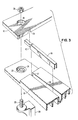
- FIG. 1 A preferred embodiment of a plastic dolly in accordance with the present invention is illustrated in Figure 1 and generally designated 10.
- Dolly 10 includes longitudinal side member 12, 14, illustrated in Figures 4-8, and transverse end members 16, 18, illustrated in Figures 9-13, coupled to form a frame, preferably rectangular in shape. Of course, other numbers of side members could be used to produce dollies of other shapes.
- End portions 20 of members 12, 14, 16, 18 are coupled to form a lap joint, illustrated in Figure 2 and generally designated 22.
- the end portions are preferably rabbeted so that the thickness of lap joint 22 is approximately the same as the thickness of members 12, 14, 16, 18.
- the members 12, 14, 16, 18 may all be molded in a honeycomb/cellular configuration so as to conserve product weight and materials.
- Each of the four corner lap joints 22 include caster fastening hole 24 for receiving caster bolt 26 which securely fastens the corner joints together.
- Each caster bolt 26 carries its respective dolly caster wheel 28. This construction permits the disassembly of the entire dolly upon the removal of only four bolts, thus permiting easy repair or replacement of any of the dolly elements.
- raised annular flange 30 be formed in the upper surface of each end portion 20 of side members 12, 14, surrounding caster fastening hole 24.
- Circular indentation 32 is formed on the lower surface of each end portion 20 of end members 16, 18 surrounding their caster fastening holes.
- Flange 30 and indentation 32 are shaped such that each flange 30 fits snugly within its respective indentation 32 when the lap joints are fit together.
- Caster fastening bolt 26 runs through both flange 30 and indentation 32, thus providing increased strength and rigidity for the lap joints.
- Side and end members 12, 14, 16, 18 may include recesses 33 formed in the upper surface of the members, as illustrated in Figure 14.
- Recess 33 is shaped to accomodate a caster wheel, i.e., preferably rounded, so that the dollies may be conveniently stacked for storage, etc., without having one dolly roll off the dolly beneath it.
- Side and end members may also have a beveled edge as illustrated in Figures 8 and 13.
- a long groove 34 extends longitudinally along substantially the entire length of the upper surface of at least one of the side members 12, 14. Long groove 34 accomodates a reinforcement element 36 fit snugly therewithin. Reinforcement element 36 is preferivelyably metal, although it is contemplated that other materials may be used. It is further contemplated, that in situations wherein the reinforcement element may be subject to rust or corrosion, the long grooves may be formed in the lower surface of the side members to protect the reinforcement element.
- a shorter groove 38 is formed in the underside of at least one of the end portions 20 of each end member 16, 18.
- Groove 38 extends radially outwardly from each caster fastening hole and aligns with its respective long groove 34.
- the ends of the reinforcement element fits within the corresponding shorter grooves to couple each reinforcement element between the lap joint of one end member, along the long groove, to the lap joint of the other end member to provide a key-like fit for the reinforcement element.
- Reinforcement element 36 may also have cut-out portion 40 formed in each end to fascilitate a snug fit by fitting over a rib 37 at the end of long groove 34.
- the reinforcement element is placed within the long groove in the side member. If a second reinforcement element is used, it is placed within a long groove in the other side member.
- the side members and the end members are fit together to form a frame.
- a caster fastening bolt is then inserted into the caster fastening hole at each corner of the frame, a caster is fixed to the end of each belt, and the bolt is tightened.
- each member could be rabbeted on the upper surface at one end and on the lower surface at the other end, so that each member could be interchanged and used as either a side member or an end member.
- the reinforcement elements be formed of a strong, rigid plastic material, instead of metal.
Abstract
Description
- Typically, dollies are made of relatively heavy, solid wood rectangles or wood slats with a caster fastened on the underside of each corner. These prior art dollies use, for example, metal corner plates or anchoring plates to add strength to the dolly frame, such as disclosed in U.S. Patent Nos. 1,184,079 to D'Arcy and 2,414,277 to Shepard, Jr. et. al. However, these plates are insufficient, in that they only provide reinforcement to a limited area, that is, only at the corners of the dolly. Another disadvantage to this construction is that the dolly caster is typically fastened with four bolts in order to maintain the rigidity of the dolly frame. Since all the bolts must be removed in order to disassemble the dolly, any repair or replacement of a worn element is a time consuming job.
- U.S. Patent Nos. 4,060,252 to Mowery and 4,103,857 to Levenhagen both disclose one-piece plastic transfer devices. Mowery shows a plastic dolly with plastic strengthening ribs formed on the underside of the dolly. Levenhagen discloses a one-piece plastic pallet having a steel rod for reinforcing the perimeter of the pallet. The primary disadvantage to these devices is that they are expensive to use since the entire device must be scrapped even if only a portion of it is damaged.
- It is an object of the present invention to provide a plastic dolly with reinforcement elements along substantially the entire length of the side member to add strength and rigidity.
- It is a further object of the present invention to provide a plastic dolly with elements which may be easily disassembled for repair or replacement.
- It is a further object of the present invention to provide a plastic dolly which requires only one caster bolt per caster to fascilitate ease of assembly and disassembly.
- The present invention is directed to a plastic dolly of lightweight, yet durable, construction preferably including a pair of longitudinal side members and a pair of transverse end members coupled by lap joints to form a frame, preferably rectangular in shape. The various members are molded in a honeycomb/cellular configuration to conserve product weight and materials. The end portions of each of the members may be rabbeted so that the corner joints are of aproximately equal thickness as the side and end members. Each of the four corner joints includes a caster fastening hole for receiving a caster fastening bolt which securely fastens the joints together and carries a conventional dolly caster wheel. Additional strength and rigidity is provided to at least one of the side members and to the lap joints by a long, preferably metal, reinforcement element. The reinforcement element is disposed in a long groove which extends substantially along the length of the longitudinal side member and into a smaller groove which extends radially from the caster fastening hole in the corresponding end of the transverse end member. The coupling of the reinforcement element between the end portion of one transverse element, along the longitudinal groove, to the end portion of the other transverse member provides a key-like fit for the metal reinforcement. This design exhibits high strength, rigidity and durability while being lightweight and permitting easy repair or replacement of the dolly elements.
-
- Figure 1 is an isometric view of a plastic dolly in accordance with the present invention;
- Figure 2 is a cross-sectional view, taken generally along line 2-2 of Figure 1, illustrating the lap joint of Figure 1;
- Figure 3 is an exploded view of the lap joint of Figure 1;
- Figure 4 is a top view of the side member illustrated in Figure 1;
- Figure 5 is a side view, partially in cross-section, of the side member illustrated in Figure 4;
- Figure 6 is a bottom view of the side member illustrated in Figure 4;
- Figure 7 is a cross-sectional view, taken generally along line 7-7 of Figure 6, illustrating the honeycomb/cellular configuration of the side member;
- Figure 8 is an exploded cross-sectional view, taken generally along line 8-8 of Figure 4, showing the beveled edge of the side member;
- Figure 9 is a top view of the end member illustrated in Figure 1;
- Figure 10 is a side view, partially in cross-section, of the end member illustrated in Figure 9;
- Figure 11 is a bottom view of the end member illustrated in Figure 9;
- Figure 12 is a cross-sectional view, taken generally along line 12-12 of Figure 11, of the end member showing the honeycomb/cellular configuration.
- Figure 13 is an exploded cross-sectional view, taken generally along line 13-13 of Figure 11, showing the beveled edge of the end member; and
- Figure 14 is a side view of the end member, partially in cross-section, illustrated in Figure 9 showing the rounded recess for accomodating stacked dolly caster wheels.
- A preferred embodiment of a plastic dolly in accordance with the present invention is illustrated in Figure 1 and generally designated 10. Dolly 10 includes
longitudinal side member transverse end members End portions 20 ofmembers lap joint 22 is approximately the same as the thickness ofmembers members - Each of the four
corner lap joints 22 includecaster fastening hole 24 for receivingcaster bolt 26 which securely fastens the corner joints together. Eachcaster bolt 26 carries its respectivedolly caster wheel 28. This construction permits the disassembly of the entire dolly upon the removal of only four bolts, thus permiting easy repair or replacement of any of the dolly elements. - To provide additional strength to the lap joint, it is contemplated that raised
annular flange 30 be formed in the upper surface of eachend portion 20 ofside members caster fastening hole 24.Circular indentation 32 is formed on the lower surface of eachend portion 20 ofend members Flange 30 andindentation 32 are shaped such that eachflange 30 fits snugly within itsrespective indentation 32 when the lap joints are fit together. Caster fasteningbolt 26 runs through bothflange 30 andindentation 32, thus providing increased strength and rigidity for the lap joints. - Side and
end members recesses 33 formed in the upper surface of the members, as illustrated in Figure 14.Recess 33 is shaped to accomodate a caster wheel, i.e., preferably rounded, so that the dollies may be conveniently stacked for storage, etc., without having one dolly roll off the dolly beneath it. Side and end members may also have a beveled edge as illustrated in Figures 8 and 13. - A
long groove 34 extends longitudinally along substantially the entire length of the upper surface of at least one of theside members Long groove 34 accomodates areinforcement element 36 fit snugly therewithin.Reinforcement element 36 is preferably metal, although it is contemplated that other materials may be used. It is further contemplated, that in situations wherein the reinforcement element may be subject to rust or corrosion, the long grooves may be formed in the lower surface of the side members to protect the reinforcement element. - A
shorter groove 38 is formed in the underside of at least one of theend portions 20 of eachend member long groove 34. The ends of the reinforcement element fits within the corresponding shorter grooves to couple each reinforcement element between the lap joint of one end member, along the long groove, to the lap joint of the other end member to provide a key-like fit for the reinforcement element.Reinforcement element 36 may also have cut-outportion 40 formed in each end to fascilitate a snug fit by fitting over arib 37 at the end oflong groove 34. - To assemble the plastic dolly in accordance with the present invention, as best seen in Figure 3, the reinforcement element is placed within the long groove in the side member. If a second reinforcement element is used, it is placed within a long groove in the other side member. The side members and the end members are fit together to form a frame. A caster fastening bolt is then inserted into the caster fastening hole at each corner of the frame, a caster is fixed to the end of each belt, and the bolt is tightened.
- The foregoing description is for illustrative purposes only. It is contemplated that the invention may be modified, particularly with regard to matters of shape size and arrangement of parts, within the scope of the invention as defined by the broad, general terms in which the appended claims are expressed. For example, it is contemplated that each member could be rabbeted on the upper surface at one end and on the lower surface at the other end, so that each member could be interchanged and used as either a side member or an end member. For another example, it is also contemplated that the reinforcement elements be formed of a strong, rigid plastic material, instead of metal.
Claims (12)
a pair of longitudinal side members and a pair of transverse end members coupled to form a frame said side members being formed in a honeycomb/cellular configuration;
each of said side members and said end members having end portions, said end portions interfitting to form a lap joint coupling said side members and said end members at each corner of the frame;
a caster fastening hole formed in each of said end portions for receiving a caster bolt which securely fastens each of said lap joints together and carries a dolly caster wheel;
reinforcement means coupled to at least one of said side members for reinforcing said side member.
second reinforcement means coupled to said other side member for reinforcing said other side member.
second reinforcement means coupled to said other side member for reinforcing reinforcing said other side member, wherein said second reinforcement means is disposed in a second long groove, said second long groove being formed longitudinally in the said other side member and extending substantially along the length of said other side member, and in a second short groove formed in each of said corresponding end portions of said end members and extending radially outwardly from said caster fastening to align with said second long groove, wherein the ends of said second reinforcement means fit within said second short grooves so as to couple said second reinforcement means between the lap joint of one of said end members along said second long groove, to the corresponding lap joint of the other of said end members.
coupling a reinforcement means to a longitudinal side member of said dolly to reinforce said side member;
connecting a pair of longitudinal side members, including said reinforced side member, to a pair of transverse end members by lap joints to form a frame;
placing a caster fastening bolt through a caster fastening hole formed in each of said lap joints, attaching a caster bolt to said caster fastening bolt, and tightening said caster fastening bolt.
placing a second reinforcement means within a second long groove formed in said other side member to reinforce said other side member.
Applications Claiming Priority (2)
| Application Number | Priority Date | Filing Date | Title |
|---|---|---|---|
| US858671 | 1986-05-02 | ||
| US06/858,671 US4720115A (en) | 1986-05-02 | 1986-05-02 | Plastic dolly |
Publications (2)
| Publication Number | Publication Date |
|---|---|
| EP0251439A2 true EP0251439A2 (en) | 1988-01-07 |
| EP0251439A3 EP0251439A3 (en) | 1988-01-27 |
Family
ID=25328866
Family Applications (1)
| Application Number | Title | Priority Date | Filing Date |
|---|---|---|---|
| EP87303624A Withdrawn EP0251439A3 (en) | 1986-05-02 | 1987-04-24 | Plastic dolly |
Country Status (2)
| Country | Link |
|---|---|
| US (1) | US4720115A (en) |
| EP (1) | EP0251439A3 (en) |
Cited By (13)
| Publication number | Priority date | Publication date | Assignee | Title |
|---|---|---|---|---|
| EP0312188A2 (en) * | 1987-10-13 | 1989-04-19 | Rehrig International, Inc. | Improved plastic dolly |
| EP0312187A2 (en) * | 1987-10-13 | 1989-04-19 | Rehrig International, Inc. | Plastic dolly with protective caps |
| DE9006263U1 (en) * | 1990-06-02 | 1990-09-13 | Fa. Herbert Bauer, 8391 Obernzell, De | |
| EP0487147A1 (en) * | 1990-11-19 | 1992-05-27 | Curtec Nederland B.V. | Plastic pallet |
| EP0524658A1 (en) * | 1988-08-30 | 1993-01-27 | Mark O. Uitz | Plastic pallet |
| FR2692766A1 (en) * | 1992-06-24 | 1993-12-31 | York Partners Lp | Suitcase mounted on wheels. |
| WO1994007704A1 (en) * | 1992-10-01 | 1994-04-14 | Plako Gmbh Thermoplastik Und Formenbau | Mounting for castors or runners |
| US5556118A (en) * | 1995-01-05 | 1996-09-17 | Rehrig International, Inc. | Flat bed cart |
| US5836255A (en) * | 1996-04-08 | 1998-11-17 | Uitz; Mark O. | Pallet for erected and collapsible container/pallet system |
| GB2382514A (en) * | 2001-12-01 | 2003-06-04 | Alec Reginald Beresford | Wheeled plant support assembly |
| WO2008119468A1 (en) * | 2007-03-30 | 2008-10-09 | Khs Ag | Loading and palletizing device for roll wagons, and related method |
| DE102007022686B3 (en) * | 2007-05-11 | 2008-11-27 | Khs Ag | Method and device for depalletizing and conveying trolleys |
| EP3048027A1 (en) * | 2015-01-22 | 2016-07-27 | Wanzl Metallwarenfabrik GmbH | Wheeled frame |
Families Citing this family (33)
| Publication number | Priority date | Publication date | Assignee | Title |
|---|---|---|---|---|
| US4934720A (en) * | 1989-01-09 | 1990-06-19 | Dobron Frank J | Mobile cart having adjustable supports |
| US5253887A (en) * | 1992-04-03 | 1993-10-19 | Marenger Keith J | Dolly modifying apparatus |
| US5921566A (en) * | 1998-05-15 | 1999-07-13 | Rehrig International Inc. | Dolly with one-piece plastic frame |
| US6203031B1 (en) * | 1998-12-07 | 2001-03-20 | Steelworks, Inc. | File cabinet dolly with open frame |
| US6134747A (en) * | 1999-02-10 | 2000-10-24 | Xerox Corporation | Ball caster with snap-in ball |
| DE10002210A1 (en) * | 2000-01-19 | 2001-07-26 | Ludwig Gebhardt Gmbh & Co Betr | Transport device |
| US6979005B1 (en) | 2002-06-17 | 2005-12-27 | Chriscott Supply, Inc. | Stackable dollies and dolly systems |
| US20040090029A1 (en) * | 2002-09-20 | 2004-05-13 | Akro-Mils, A Division Of Myers Industries Co. | Dolly |
| US6974140B2 (en) * | 2004-01-12 | 2005-12-13 | Timothy Neuman | Modular multiple dolly moving system |
| US20060097468A1 (en) * | 2004-11-05 | 2006-05-11 | Sugrue Albert J | Wheeled X-frame table dolly |
| DE202005007939U1 (en) * | 2005-05-17 | 2006-09-28 | Wanzl Metallwarenfabrik Gmbh | Goods cart for use in e.g. self-service business, defines gap for receiving horizontal flat steel bar in each corner of one-piece shelf |
| US20070228681A1 (en) * | 2006-03-31 | 2007-10-04 | Schenker David A | File Cabinet Caddy |
| US8668211B2 (en) * | 2008-09-05 | 2014-03-11 | David L. King | High strength plastic furniture dolly |
| US8544859B2 (en) | 2010-08-20 | 2013-10-01 | Sela Products, Llc | Dolly |
| DE102011084814A1 (en) * | 2011-10-19 | 2013-04-25 | Osram Opto Semiconductors Gmbh | MOUNTING ELEMENT FOR HOLDING AT LEAST ONE FLAT LIGHT LAMP, SET OF A MULTIPLE OF VERSIONS AND A MULTIPLE OF LONG-SLIPED HOLDING BODIES AND LUMINAIRE |
| US8850656B2 (en) | 2012-06-26 | 2014-10-07 | Luca Buttazzoni | Castor assembly for a modular dolly |
| US9010798B2 (en) | 2012-07-23 | 2015-04-21 | Luca Buttazzoni | Self-contained dolly assembly |
| US20140367938A1 (en) * | 2013-06-18 | 2014-12-18 | Jimontanae Rax McBride | Corner Dolly Skate |
| US9409585B2 (en) | 2013-07-15 | 2016-08-09 | Luca Buttazzoni | Castor supported dolly assembly capable of being made from lightweight materials and of being used as a pallet assembly |
| US8876145B1 (en) | 2013-07-15 | 2014-11-04 | Luca Buttazzoni | Castor supported dolly assembly capable of being made from lightweight materials and so as to be disposable or severable |
| US8910955B1 (en) | 2013-12-03 | 2014-12-16 | Luca Buttazzoni | Lightweight dolly assembly |
| USD754462S1 (en) | 2014-04-23 | 2016-04-26 | Innerworkings, Inc. | Base with wheels for a temporary display rack |
| USD735510S1 (en) * | 2014-04-23 | 2015-08-04 | Innerworkings, Inc. | Base with wheels for a temporary display rack |
| US10021995B2 (en) | 2014-04-23 | 2018-07-17 | Inner Workings, Inc. | Temporary display rack |
| USD763017S1 (en) | 2014-04-23 | 2016-08-09 | Innerworkings, Inc. | Temporary display rack flat kit |
| USD775871S1 (en) | 2014-04-23 | 2017-01-10 | Innerworkings, Inc. | Temporary display rack |
| US10123634B2 (en) | 2014-04-23 | 2018-11-13 | Innerworkings, Inc. | Display unit configured for quick assembly |
| RU2609491C1 (en) * | 2015-07-14 | 2017-02-02 | Игнат Игоревич Иванов | Collapsible cradle |
| US10504161B2 (en) | 2015-12-02 | 2019-12-10 | Innerworkings, Inc. | Systems and methods for baselining using multiple baseline methodologies |
| USD827340S1 (en) | 2016-03-23 | 2018-09-04 | Innerworkings, Inc. | Display unit |
| USD869114S1 (en) * | 2018-02-26 | 2019-12-03 | Grow Solutions Tech Llc | Cart |
| US11173939B2 (en) | 2018-08-20 | 2021-11-16 | Rehrig Pacific Company | Bakery dolly |
| USD967590S1 (en) * | 2021-01-01 | 2022-10-18 | Texas Intelligent Integration LLC | Wheeled platform carrier |
Citations (3)
| Publication number | Priority date | Publication date | Assignee | Title |
|---|---|---|---|---|
| FR2166343A1 (en) * | 1972-01-07 | 1973-08-17 | Orlac | |
| US4055362A (en) * | 1976-06-18 | 1977-10-25 | Metropolitan Wire Corporation | Bumper assembly for a rolling cart |
| US4060252A (en) * | 1974-11-06 | 1977-11-29 | Geoffrey John Mowery | Ball type transfer apparatus |
Family Cites Families (7)
| Publication number | Priority date | Publication date | Assignee | Title |
|---|---|---|---|---|
| US2610750A (en) * | 1948-10-01 | 1952-09-16 | Reed O Hulbert | Motor vehicle wheel truck |
| US3582102A (en) * | 1969-03-25 | 1971-06-01 | Towers Sunderland Ltd | Containers |
| US3902692A (en) * | 1973-02-05 | 1975-09-02 | Westmoreland Plastics Co | Combined assembly and shipping skid |
| US3964762A (en) * | 1974-07-22 | 1976-06-22 | Adams John F | Folding luggage carrier |
| GB1571190A (en) * | 1975-12-09 | 1980-07-09 | Wavin Bv | Pallets |
| US4077644A (en) * | 1976-10-12 | 1978-03-07 | Rubbermaid Commercial Products Inc. | Platform hand truck |
| US4577448A (en) * | 1981-06-17 | 1986-03-25 | The British Picker Company, Ltd. | Floors |
-
1986
- 1986-05-02 US US06/858,671 patent/US4720115A/en not_active Expired - Lifetime
-
1987
- 1987-04-24 EP EP87303624A patent/EP0251439A3/en not_active Withdrawn
Patent Citations (3)
| Publication number | Priority date | Publication date | Assignee | Title |
|---|---|---|---|---|
| FR2166343A1 (en) * | 1972-01-07 | 1973-08-17 | Orlac | |
| US4060252A (en) * | 1974-11-06 | 1977-11-29 | Geoffrey John Mowery | Ball type transfer apparatus |
| US4055362A (en) * | 1976-06-18 | 1977-10-25 | Metropolitan Wire Corporation | Bumper assembly for a rolling cart |
Cited By (19)
| Publication number | Priority date | Publication date | Assignee | Title |
|---|---|---|---|---|
| EP0312188A2 (en) * | 1987-10-13 | 1989-04-19 | Rehrig International, Inc. | Improved plastic dolly |
| EP0312187A2 (en) * | 1987-10-13 | 1989-04-19 | Rehrig International, Inc. | Plastic dolly with protective caps |
| EP0312188A3 (en) * | 1987-10-13 | 1990-06-20 | Rehrig International, Inc. | Improved plastic dolly |
| EP0312187A3 (en) * | 1987-10-13 | 1990-06-20 | Rehrig International, Inc. | Plastic dolly with protective caps |
| EP0524658A1 (en) * | 1988-08-30 | 1993-01-27 | Mark O. Uitz | Plastic pallet |
| DE9006263U1 (en) * | 1990-06-02 | 1990-09-13 | Fa. Herbert Bauer, 8391 Obernzell, De | |
| EP0487147A1 (en) * | 1990-11-19 | 1992-05-27 | Curtec Nederland B.V. | Plastic pallet |
| FR2696083A1 (en) * | 1992-06-24 | 1994-04-01 | York Partners Lp | Suitcase mounted on wheels. |
| FR2692766A1 (en) * | 1992-06-24 | 1993-12-31 | York Partners Lp | Suitcase mounted on wheels. |
| WO1994007704A1 (en) * | 1992-10-01 | 1994-04-14 | Plako Gmbh Thermoplastik Und Formenbau | Mounting for castors or runners |
| US5524322A (en) * | 1992-10-01 | 1996-06-11 | Plako Gmbh Thermoplastik Und Formenbau | Retaining device for casters and slides |
| US5556118A (en) * | 1995-01-05 | 1996-09-17 | Rehrig International, Inc. | Flat bed cart |
| US5836255A (en) * | 1996-04-08 | 1998-11-17 | Uitz; Mark O. | Pallet for erected and collapsible container/pallet system |
| GB2382514A (en) * | 2001-12-01 | 2003-06-04 | Alec Reginald Beresford | Wheeled plant support assembly |
| WO2008119468A1 (en) * | 2007-03-30 | 2008-10-09 | Khs Ag | Loading and palletizing device for roll wagons, and related method |
| DE102007015751B3 (en) * | 2007-03-30 | 2008-12-24 | Khs Ag | Loading and palletizing device for trolley and associated method |
| US8356458B2 (en) | 2007-03-30 | 2013-01-22 | Khs Gmbh | Loading and palletizing device for roll trucks, such as dollies, and the associated method |
| DE102007022686B3 (en) * | 2007-05-11 | 2008-11-27 | Khs Ag | Method and device for depalletizing and conveying trolleys |
| EP3048027A1 (en) * | 2015-01-22 | 2016-07-27 | Wanzl Metallwarenfabrik GmbH | Wheeled frame |
Also Published As
| Publication number | Publication date |
|---|---|
| EP0251439A3 (en) | 1988-01-27 |
| US4720115A (en) | 1988-01-19 |
Similar Documents
| Publication | Publication Date | Title |
|---|---|---|
| EP0251439A2 (en) | Plastic dolly | |
| EP0312188A2 (en) | Improved plastic dolly | |
| US4261470A (en) | Collapsible rack | |
| US5456189A (en) | Shipping pallet | |
| KR100828421B1 (en) | A assembly type pallet | |
| US5809902A (en) | Pallet | |
| US5921566A (en) | Dolly with one-piece plastic frame | |
| US4366905A (en) | Plastic material handling rack | |
| US5383409A (en) | Corrugated board pallet | |
| US8544859B2 (en) | Dolly | |
| EP0199513B1 (en) | Cargo pallet | |
| GB2379651A (en) | Load supporting platform | |
| JPH02169373A (en) | Deck loading apparatus of truck body | |
| US5685233A (en) | Recyclable pallet assembly | |
| EP1744966B1 (en) | Palette | |
| US5611554A (en) | Cart | |
| US3882796A (en) | Metal pallet | |
| US20020078863A1 (en) | Metal Pallet | |
| US20050160949A1 (en) | Interlocking modular tubular pallet | |
| JPH0449071Y2 (en) | ||
| JPH07329971A (en) | Assembled pallet | |
| JPH0685230U (en) | palette | |
| JPS585657Y2 (en) | Frame-shaped transport trolley | |
| JPH08310405A (en) | Transport carriage | |
| JP2555352Y2 (en) | Concrete formwork with flat reinforcing ribs |
Legal Events
| Date | Code | Title | Description |
|---|---|---|---|
| PUAI | Public reference made under article 153(3) epc to a published international application that has entered the european phase |
Free format text: ORIGINAL CODE: 0009012 |
|
| PUAL | Search report despatched |
Free format text: ORIGINAL CODE: 0009013 |
|
| AK | Designated contracting states |
Kind code of ref document: A2 Designated state(s): AT BE CH DE ES FR GB GR IT LI LU NL SE |
|
| AK | Designated contracting states |
Kind code of ref document: A3 Designated state(s): AT BE CH DE ES FR GB GR IT LI LU NL SE |
|
| 17P | Request for examination filed |
Effective date: 19880713 |
|
| 17Q | First examination report despatched |
Effective date: 19900124 |
|
| STAA | Information on the status of an ep patent application or granted ep patent |
Free format text: STATUS: THE APPLICATION IS DEEMED TO BE WITHDRAWN |
|
| 18D | Application deemed to be withdrawn |
Effective date: 19900911 |