EP0251316B1 - Automatic lock slider for slide fastener - Google Patents
Automatic lock slider for slide fastener Download PDFInfo
- Publication number
- EP0251316B1 EP0251316B1 EP87109482A EP87109482A EP0251316B1 EP 0251316 B1 EP0251316 B1 EP 0251316B1 EP 87109482 A EP87109482 A EP 87109482A EP 87109482 A EP87109482 A EP 87109482A EP 0251316 B1 EP0251316 B1 EP 0251316B1
- Authority
- EP
- European Patent Office
- Prior art keywords
- locking
- prong
- locking prong
- automatic lock
- locking member
- Prior art date
- Legal status (The legal status is an assumption and is not a legal conclusion. Google has not performed a legal analysis and makes no representation as to the accuracy of the status listed.)
- Expired - Lifetime
Links
Images


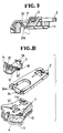


Classifications
-
- A—HUMAN NECESSITIES
- A44—HABERDASHERY; JEWELLERY
- A44B—BUTTONS, PINS, BUCKLES, SLIDE FASTENERS, OR THE LIKE
- A44B19/00—Slide fasteners
- A44B19/24—Details
- A44B19/26—Sliders
-
- A—HUMAN NECESSITIES
- A44—HABERDASHERY; JEWELLERY
- A44B—BUTTONS, PINS, BUCKLES, SLIDE FASTENERS, OR THE LIKE
- A44B19/00—Slide fasteners
- A44B19/24—Details
- A44B19/26—Sliders
- A44B19/30—Sliders with means for locking in position
- A44B19/306—Sliders with means for locking in position in the form of a locking spring member actuated by the pull member
-
- Y—GENERAL TAGGING OF NEW TECHNOLOGICAL DEVELOPMENTS; GENERAL TAGGING OF CROSS-SECTIONAL TECHNOLOGIES SPANNING OVER SEVERAL SECTIONS OF THE IPC; TECHNICAL SUBJECTS COVERED BY FORMER USPC CROSS-REFERENCE ART COLLECTIONS [XRACs] AND DIGESTS
- Y10—TECHNICAL SUBJECTS COVERED BY FORMER USPC
- Y10T—TECHNICAL SUBJECTS COVERED BY FORMER US CLASSIFICATION
- Y10T24/00—Buckles, buttons, clasps, etc.
- Y10T24/25—Zipper or required component thereof
- Y10T24/2561—Slider having specific configuration, construction, adaptation, or material
- Y10T24/2566—Slider having specific configuration, construction, adaptation, or material including position locking-means attached thereto
-
- Y—GENERAL TAGGING OF NEW TECHNOLOGICAL DEVELOPMENTS; GENERAL TAGGING OF CROSS-SECTIONAL TECHNOLOGIES SPANNING OVER SEVERAL SECTIONS OF THE IPC; TECHNICAL SUBJECTS COVERED BY FORMER USPC CROSS-REFERENCE ART COLLECTIONS [XRACs] AND DIGESTS
- Y10—TECHNICAL SUBJECTS COVERED BY FORMER USPC
- Y10T—TECHNICAL SUBJECTS COVERED BY FORMER US CLASSIFICATION
- Y10T24/00—Buckles, buttons, clasps, etc.
- Y10T24/25—Zipper or required component thereof
- Y10T24/2561—Slider having specific configuration, construction, adaptation, or material
- Y10T24/2566—Slider having specific configuration, construction, adaptation, or material including position locking-means attached thereto
- Y10T24/2568—Protrusion on pull tab directly engaging interlocking surfaces
-
- Y—GENERAL TAGGING OF NEW TECHNOLOGICAL DEVELOPMENTS; GENERAL TAGGING OF CROSS-SECTIONAL TECHNOLOGIES SPANNING OVER SEVERAL SECTIONS OF THE IPC; TECHNICAL SUBJECTS COVERED BY FORMER USPC CROSS-REFERENCE ART COLLECTIONS [XRACs] AND DIGESTS
- Y10—TECHNICAL SUBJECTS COVERED BY FORMER USPC
- Y10T—TECHNICAL SUBJECTS COVERED BY FORMER US CLASSIFICATION
- Y10T24/00—Buckles, buttons, clasps, etc.
- Y10T24/25—Zipper or required component thereof
- Y10T24/2561—Slider having specific configuration, construction, adaptation, or material
- Y10T24/2566—Slider having specific configuration, construction, adaptation, or material including position locking-means attached thereto
- Y10T24/257—Slider having specific configuration, construction, adaptation, or material including position locking-means attached thereto having surface engaging element shifted by reorientation of pull tab
- Y10T24/2571—Resilient or spring biased element
Definitions
- the present invention relates to an automatically lockable slider for a slide fastener and more particularly a slider having a locking prong spring-biased to engage with a coupling head of a coupling element at an intermeshing region in its Y-shaped guide channel.
- a typical automatic lock slider for a slide fastener includes a pull tab and a locking prong operatively associated therewith.
- the locking prong is normally urged downwardly into the path of coupling elements in the slider, and can be retracted out of the path by lifting the pull tab on the slider.
- Japanese Utility Model Laid-Open Publication No. 51-126703 discloses a lockable slider having lock and ratchet functions.
- a cavity is defined in the bottom surface of the guide channel in confrontation with the locking prong so as to allow the coupling element to tilt and sink therein to pass underneath the prong when the fastener stringers are forcibly spread apart.
- the maximum allowable lock strength of the locking prong is defined by a critical pressure at which the coupling elements begin to shift out of position on the fastener or otherwise sustain damage. This means that the coupling element does not initiate tilting until it is engaged by the locking prong with considerable force nearly reaching the critical pressure. Under the influence of such pressure, the locking prong is susceptible to abrasion, which in turn makes the slider malfunction or be unlockable. Another problem with this prior slider is that it is difficult to attain the necessary dimensional precision in the finish of its parts.
- the present invention seeks to provide an improved lock slider which is capable of smooth lock and ratchet performance over extended service life without involving separated, displaced or damaged fastener elements which would otherwise result from repeated ratchet action.
- An automatic lock slider according to the preamble of claim 1 is disclosed in principle in GB-A-602 543 and FR-A-2 213 747.
- the locking member is arranged such that movement of the slider in the direction of opening is reliably prevented when the stringer tapes are pulled apart from each other in transverse direction.
- Figure 1 is a horizontal cross-sectional view of a slider according to an embodiment of the present invention, with a locking prong in a locking mode;
- Figure 2 is a vertical cross-sectional view taken along line II - II of Figure 1;
- Figure 3 is similar to Figure 2, showing the locking prong in a ratchet mode
- Figure 4 is an explosive view of the slider of Figure 1;
- Figures 5A, 5B and 5C are side elevational views of various lower ends of the locking prong according to embodiments of the invention.
- Figure 6 is a perspective view of a lower wing of a slider body provided with a raised guide portion
- Figure 7 is a vertical cross-sectional view of the slider, showing a manner in which the coupling element is forced against the raised portion;
- FIGS 8 and 9 are vertical cross-sectional views, partly broken away, of modifications of the locking prong
- Figure 10 is an explosive view of a modified slider having a pair of locking prongs
- Figure 11 is a horizontal cross-sectional view of the slider of Figure l0;
- Figure 12 is a vertical cross-sectional view taken along line XII - XII of Figure 11;
- Figure 13 is a vertical cross-sectional view of a slider according to another embodiment of the invention.
- Figure 14 is a horizontal cross-sectional view taken along line XIV - XIV of Figure 13;
- Figure 15 is a side elevational view of a locking prong of the slider shown in Figure 13, showing a manner in which the locking prong locks the coupling element;
- Figure 16 is a vertical cross-sectional view of the slider of Figure 13, showing the coupling element positioned on the raised portion;
- Figure 17 is an explosive view of an another modification of the slider fastener
- Figure 18 is a perspective view of modified parts of the slider shown in Figure 17;
- Figure 19 is a schematical plan view of a prior slider, showing a pull tab laterally angularly displaced relative to a slider body.
- Figures 1 - 4 show inclusively an automatic lock slider according to a first embodiment of the present invention.
- the slider includes a slider body 1, a locking member 3 mounted on the slider body and a pull tab 2 pivotably held by the locking member on the slider body.
- the slider body 1 includes upper and lower wings 4, 5 spaced in parallel to each other and a connecting neck 6 joining together the two wings at their front ends, thereby defining a Y-shaped guide channel 7 for the passage of a pair of coupling element rows 31 carried respectively on a pair of stringer tapes.
- the neck extends vertically and has a V-shaped horizontal cross section such that it defines a retention groove 8 for receiving one or distal end of the locking member 3 as described later on.
- the upper wing has two apertures 10, 12 both communicating with the guide channel 7.
- One or front aperture 10 is disposed adjacent to the neck 6 and the other or rear aperture 12 is disposed adjacent to the rear end of the upper wing 4.
- the front aperture 10 is disposed at a position laterally displaced from a longitudinal axis of the slider body 1 for the purpose described later on.
- Formed between the two apertures 10, 12 is a retaining lug 11.
- the locking member is made of a resilient material such as a metal plate and includes a downwardly curved front portion 14, an intermediate portion 17 extending rearwardly from an upper curved part 16 of the front portion and a bulged portion 18 contiguous to the intermediate portion.
- the locking member 3 is retained at the distal end 15 of the front portion 14 received in the retention groove 8 such that the intermediate portion 17 and the bulged portion 18 are urged toward the upper wing 4. Specifically, a lower surface 17 a of the intermediate portion 17 is urged downwardly and facewise against the upper wing 4. The distal end 15 is engaged by a pair of stepped portions 9 formed at a lower end of the groove.
- the locking member extends rearwardly and terminates in a rear end 19 disposed in the rear aperture 12 of the upper wing.
- the locking member has a window 22 defined in a rear slanted wall of the bulged portion 18.
- the retaining lug 11 extends upwardly rearwardly through the window 22 and terminates above the rear end 19 of the locking member 3 such that the lug 11 restricts an excessive movement of the locking member in both lateral and upward directions.
- a locking prong 20 extends downwardly forwardly from the intermediate portion 17 through the laterally displaced front aperture 10 into the guide channel 7 as shown in Figure 2.
- the locking prong 20 has its lower end 21 normally positioned in an intermeshing region defined adjacent to a diverging or branched point of the Y-shaped guide channel 7, in which region a mating pair of coupling elements are brought into and out of intermeshing engagement by moving the slider relative to the coupling element rows.
- the intermeshing region is an area where the mating pair of coupling elements are on the verge of coupling together or on the verge of separating from each other.
- the lower end 21 of the locking prong 20 has an abutment surface on its lower end at somewhat rear surface.
- the abutment surface is defined by a rounded or smooth surface at which the locking prong engages a tapered surface of the coupling head 32 of the coupling element 31.
- the prong 20 and hence the lower end 21 are normally urged downwardly toward the lower wing 5 since the intermediate portion 17 supporting the same is urged downwardly.
- Provision of the smooth abutment surface on the locking prong prevents the coupling elements from being damaged or displaced by the repeated manipulation of the slider in its ratchet mode.
- the coupling element is in a discrete form, and has the tapered coupling head projecting forwardly.
- coupling element is not limited to this type.
- Figures 5A, 5B and 5C show exemplary forms of the lower end of the locking prong 20.
- the locking prong 20 has an upwardly curved end 2 1a providing the abutment surface in the form of a rounded lower surface.
- Figure 5B shows a lower bent end 2 1b having a lower surface engageable with a tapered surface of the coupling head 32 in a surface-contacting manner.
- Figure 5C shows a lower bent end 2 1c having a lower rounded corner defining the abutment surface.
- the pull tab 2 has bifurcated support legs 23 and a cam shaft 24 extending between distal ends of the legs 23, thereby defining an opening 25.
- the cam shaft 24 is received in the bulged portion 18 and held against the upper wing 4 such that the pull tab is pivotally movable about the cam shaft 24 and also biased by the retention force of the bulged portion 18 to lie on the upper wing 4 of the slider body 1.
- the locking prong 20 is normally spring-biased downwardly and is adapted to engage with a coupling head 32 of the coupling element 31 in the intermeshing region.
- the locking prong 20 When the locking prong 20 is in a locking position ( Figure 2) where the locking prong 20 is positioned in engagement with the coupling element 31, the prong continues to push down the coupling element for thereby locking the slider.
- the pull tab In a normal unlocking operation, the pull tab is manually raised to retract the locking prong 20 out of the guide channel. More specifically, the pivotal movement of the pull tab 2 causes the cam shaft to rotate and to move the bulged portion 18 and hence the locking prong 20 upwardly. At this time, the lower end 21 of the prong 20 is retracted out of the guide channel 7.
- the cam shaft 24 When the pull tab 2 is released, the cam shaft 24 is urged by the bulged portion 18 to rotate to cause the pull tab 2 to lie on the upper wing 4 of the slider body 2, whereupon the locking prong 20 is also urged down into the guide channel.
- the slide fastener can be spread open also by pulling laterally the fastener stringers 30, 30 without manipulating the slider.
- the coupling element 31 Under the continued pull force applied to the stringers, the coupling element 31 is moved forwardly relative to the slider body 1 and hence the locking prong, whereupon the coupling head 32 slides on the smooth abutment surface of the prong 20 and advances pushing up the latter gradually as shown in Figure 3. Consequently, the coupling element 31 clears the prong 20 and thus effecting a ratchet function.
- the successive coupling elements repeat the same action for thereby making the slide fastener spread apart.
- the coupling element 31 are engaged at their coupling heads 32 by the locking prong 20. Provision of the abutment surface of the prong 20 protects the coupling elements from mechanical damages such as a shifting or a wearing of the coupling elements which otherwise take place.
- a raised guide portion 27 is formed on the inner surface of the lower wing 5 of the slider body 1.
- the raised guide portion 27 is disposed in the intermeshing region of the guide channel 7 in a substantially vertical registry with the lower end 21 of the prong.
- the raised portion extends complementary in contour with a lower part of the coupling head 32 so as to occupy a gap between the coupling head 32 and the inner surface of the lower wing 5 i.e. the bottom surface of the guide channel 7, as shown in Figure 7.
- the raised portion 27 guides the coupling elements 31 and prevents the same to roll about its longitudinal axis of the coupling element in the intermeshing region as the latter advance on and along the raised portion 27 with the coupling heads 32 engaged by the locking prong 20.
- the raised portion 27 assists the locking prong 20 in locking the element 31 in a more stable manner.
- the locking prong 20 may extend down rearwardly from the intermediate portion 17 as shown in Figure 8.
- Figure 9 shows another modified locking prong 20 of a V-shape formed by punching the intermediate portion 17.
- the slider may be provided with an additional locking prong 20 ⁇ as shown in Figures 10, 11 and 12.
- the locking prong 20 ⁇ extends through an aperture 10 ⁇ of the upper wing 4 into the intermeshing region of the Y-shaped guide channel 7 in a similar manner to the locking prong 20 except that the additional prong 20 ⁇ is offset rearwardly relative to the prong 20 such that the locking prong 20 engages one coupling element 31 and the locking prong 20 ⁇ engages the mating coupling element 31 as best shown in Figure 11.
- the cam shaft 24 has a recessed shaft portion 24a so as not to interfere with the rearwardly offset prong 20 ⁇ .
- a retaining lug 11a of the upper wing 4 projects upwardly forwardly for the same purpose of the lug 11.
- Figures 13 to 16 show an automatic lock slider according to another embodiment of the invention. This embodiment is similar to those described hereinabove, but a locking prong 40 extends vertically down into the guide channel 7 through the aperture 10. An upper part 16 of the front portion 14 and the intermediate portion 17 are spaced from the slider body 1 as shown in Figure 13. The prong 40 depends from a junction at which the intermediate portion 17 and the bulged portion 18 are connected to each other.
- the locking member 3 is urged against the upper wing 4 and in contact with the latter at points m , n .
- the point m is disposed at the junction between the intermediate portion 17 and the bulged portion 18, and the point n is disposed on an inner surface of a rear slanted wall of the bulged portion 18.
- the locking member is spring-biased and pivotally movable about the distal end 15, for thereby projecting the locking prong 40 into the guide channel 7.
- a lower end 41 of the prong 40 is positioned in the intermeshing region in a similar manner as the prong 20.
- the lower end 41 has a rearwardly canted surface defining the abutment surface engageable with a forwardly tapered surface of the coupling head 32.
- the locking prong 40 has a rectangular horizontal cross section and is twisted about its axis such that the rectangle is orientated in the same direction as the coupling head 32 of the coupling element 31 positioned in contact with the lower end 41 of the prong in the intermeshing region.
- a rear side face of the rectangular prong 40 extends in parallel to a longitudinal axis of a leg 33 of the coupling element 31.
- a raised guide portion 27 a is formed on the inner surface of the lower wing 7 in the intermeshing region. As best shown in Figure 16, the raised portion 27 a has a pair of laterally slanted surfaces having a ridge coaxial with the axis of the slider body 1. The raised portion 27 a makes the guide channel 7 receive and guide the coupling elements 31 in a more snugly manner.
- the downward movement of the locking prong 40 is restricted by the upper wing 4 which engages the prong at the points m , n , and the upward movement of the same by the retention lug 11 which engages the rear end 19 thereof.
- the vertical locking prong 40 is lifted by the horizontal or forward pushing force of the coupling element 31 in more efficient and more responsive manner than the slanted locking prong 20. This is because the prong 40 is pivotable about a point, i.e. the distal end of the locking member 15, which is disposed relatively remotely from the prong. The more remotely the distal end or pivot portion of the locking member is disposed from the prong or action point, the more responsively the prong is moved by the force caused thereon by the coupling element when the latter is forced to move through the guide channel.
- Figures 17 and 18 show modifications of the pull tab 2.
- the pull tab 2 When the pull tab 2 is released from the operator's fingers in a vertical unlocking position, the pull tab is forced to lie down under the biase force of the locking member 3 through the cam effect of the cam shaft 24. On such occasion the pull tab is apt to fall down into a laterally displaced position as shown in Figure 19, and the distal end portions of the legs 23 are often clinched between the locking member 2 and the upper wing of the slider body 1. As a result, the locking prong is blocked and kept retracted from the guide channel 7 as indicated by a phantom line in Figure 19, although the pull tab is in the horizontal locking position. This is because the cam shaft 24 is disposed offset downwardly relative to the upper surface of the legs 23 and hence of the pull tab 2.
- the pull tab 2 of Figure 17 is provided with a pair of stepped guide recesses 26, 26 at respective inside corners of the distal ends of the legs 23.
- the guide recess may be in the form of a canted corner recess 26 a as shown in Figure 18.
Landscapes
- Slide Fasteners (AREA)
- Buckles (AREA)
Description
- The present invention relates to an automatically lockable slider for a slide fastener and more particularly a slider having a locking prong spring-biased to engage with a coupling head of a coupling element at an intermeshing region in its Y-shaped guide channel.
- A typical automatic lock slider for a slide fastener includes a pull tab and a locking prong operatively associated therewith. The locking prong is normally urged downwardly into the path of coupling elements in the slider, and can be retracted out of the path by lifting the pull tab on the slider.
- As is often the case with slide fasteners having such sliders and used on a rigid garment fabric, they are opened by grabbing the garment fabric and spreading the fastener stringers forcibly apart instead of manipulating the pull tab on the slider. A similar scene is commonly witnessed at the site of sewing slide fasteners to the rigid garment fabric, namely a denim.
- Japanese Utility Model Laid-Open Publication No. 51-126703 discloses a lockable slider having lock and ratchet functions. To effect the ratchet function, a cavity is defined in the bottom surface of the guide channel in confrontation with the locking prong so as to allow the coupling element to tilt and sink therein to pass underneath the prong when the fastener stringers are forcibly spread apart.
- With this type of slider, the maximum allowable lock strength of the locking prong is defined by a critical pressure at which the coupling elements begin to shift out of position on the fastener or otherwise sustain damage. This means that the coupling element does not initiate tilting until it is engaged by the locking prong with considerable force nearly reaching the critical pressure. Under the influence of such pressure, the locking prong is susceptible to abrasion, which in turn makes the slider malfunction or be unlockable. Another problem with this prior slider is that it is difficult to attain the necessary dimensional precision in the finish of its parts.
- The present invention seeks to provide an improved lock slider which is capable of smooth lock and ratchet performance over extended service life without involving separated, displaced or damaged fastener elements which would otherwise result from repeated ratchet action.
- The above object is achieved by the provision of a lock slider as characterized in
claim 1. - An automatic lock slider according to the preamble of
claim 1 is disclosed in principle in GB-A-602 543 and FR-A-2 213 747. In these conventional lock sliders, the locking member is arranged such that movement of the slider in the direction of opening is reliably prevented when the stringer tapes are pulled apart from each other in transverse direction. - Many other advantages and features of the present invention will become manifest to those versed in the art upon making reference to the detailed description and the accompanying sheets of drawings in which preferred structural embodiments incorporating the principles of the present invention are shown by way of illustrative example.
- Figure 1 is a horizontal cross-sectional view of a slider according to an embodiment of the present invention, with a locking prong in a locking mode;
- Figure 2 is a vertical cross-sectional view taken along line II - II of Figure 1;
- Figure 3 is similar to Figure 2, showing the locking prong in a ratchet mode;
- Figure 4 is an explosive view of the slider of Figure 1;
- Figures 5A, 5B and 5C are side elevational views of various lower ends of the locking prong according to embodiments of the invention;
- Figure 6 is a perspective view of a lower wing of a slider body provided with a raised guide portion;
- Figure 7 is a vertical cross-sectional view of the slider, showing a manner in which the coupling element is forced against the raised portion;
- Figures 8 and 9 are vertical cross-sectional views, partly broken away, of modifications of the locking prong;
- Figure 10 is an explosive view of a modified slider having a pair of locking prongs;
- Figure 11 is a horizontal cross-sectional view of the slider of Figure l0;
- Figure 12 is a vertical cross-sectional view taken along line XII - XII of Figure 11;
- Figure 13 is a vertical cross-sectional view of a slider according to another embodiment of the invention;
- Figure 14 is a horizontal cross-sectional view taken along line XIV - XIV of Figure 13;
- Figure 15 is a side elevational view of a locking prong of the slider shown in Figure 13, showing a manner in which the locking prong locks the coupling element;
- Figure 16 is a vertical cross-sectional view of the slider of Figure 13, showing the coupling element positioned on the raised portion;
- Figure 17 is an explosive view of an another modification of the slider fastener;
- Figure 18 is a perspective view of modified parts of the slider shown in Figure 17; and
- Figure 19 is a schematical plan view of a prior slider, showing a pull tab laterally angularly displaced relative to a slider body.
- The invention will be better understood from the following detailed description taken in conjunction with the accompanying drawings, in which like numerals refer to like and corresponding parts throughout the several views.
- Figures 1 - 4 show inclusively an automatic lock slider according to a first embodiment of the present invention. The slider includes a
slider body 1, alocking member 3 mounted on the slider body and apull tab 2 pivotably held by the locking member on the slider body. - The
slider body 1 includes upper andlower wings neck 6 joining together the two wings at their front ends, thereby defining a Y-shaped guide channel 7 for the passage of a pair ofcoupling element rows 31 carried respectively on a pair of stringer tapes. The neck extends vertically and has a V-shaped horizontal cross section such that it defines aretention groove 8 for receiving one or distal end of thelocking member 3 as described later on. - The upper wing has two
apertures guide channel 7. One orfront aperture 10 is disposed adjacent to theneck 6 and the other orrear aperture 12 is disposed adjacent to the rear end of theupper wing 4. Thefront aperture 10 is disposed at a position laterally displaced from a longitudinal axis of theslider body 1 for the purpose described later on. Formed between the twoapertures retaining lug 11. - The locking member is made of a resilient material such as a metal plate and includes a downwardly
curved front portion 14, anintermediate portion 17 extending rearwardly from an uppercurved part 16 of the front portion and a bulgedportion 18 contiguous to the intermediate portion. - The
locking member 3 is retained at thedistal end 15 of thefront portion 14 received in theretention groove 8 such that theintermediate portion 17 and thebulged portion 18 are urged toward theupper wing 4. Specifically, alower surface 17a of theintermediate portion 17 is urged downwardly and facewise against theupper wing 4. Thedistal end 15 is engaged by a pair ofstepped portions 9 formed at a lower end of the groove. The locking member extends rearwardly and terminates in arear end 19 disposed in therear aperture 12 of the upper wing. The locking member has awindow 22 defined in a rear slanted wall of the bulgedportion 18. Theretaining lug 11 extends upwardly rearwardly through thewindow 22 and terminates above therear end 19 of thelocking member 3 such that thelug 11 restricts an excessive movement of the locking member in both lateral and upward directions. - A
locking prong 20 extends downwardly forwardly from theintermediate portion 17 through the laterally displacedfront aperture 10 into theguide channel 7 as shown in Figure 2. Thelocking prong 20 has itslower end 21 normally positioned in an intermeshing region defined adjacent to a diverging or branched point of the Y-shaped guide channel 7, in which region a mating pair of coupling elements are brought into and out of intermeshing engagement by moving the slider relative to the coupling element rows. - More specifically, the intermeshing region is an area where the mating pair of coupling elements are on the verge of coupling together or on the verge of separating from each other.
- The
lower end 21 of thelocking prong 20 has an abutment surface on its lower end at somewhat rear surface. The abutment surface is defined by a rounded or smooth surface at which the locking prong engages a tapered surface of thecoupling head 32 of thecoupling element 31. - The
prong 20 and hence thelower end 21 are normally urged downwardly toward thelower wing 5 since theintermediate portion 17 supporting the same is urged downwardly. - Provision of the smooth abutment surface on the locking prong prevents the coupling elements from being damaged or displaced by the repeated manipulation of the slider in its ratchet mode.
- In the illustrated embodiment, the coupling element is in a discrete form, and has the tapered coupling head projecting forwardly. However, coupling element is not limited to this type.
- Figures 5A, 5B and 5C show exemplary forms of the lower end of the
locking prong 20. In Figure 5A, thelocking prong 20 has an upwardlycurved end 21a providing the abutment surface in the form of a rounded lower surface. Figure 5B shows a lower bent end 21bhaving a lower surface engageable with a tapered surface of thecoupling head 32 in a surface-contacting manner. Figure 5C shows alower bent end 21c having a lower rounded corner defining the abutment surface. - As shown in Figure 4, the
pull tab 2 has bifurcatedsupport legs 23 and acam shaft 24 extending between distal ends of thelegs 23, thereby defining anopening 25. Thecam shaft 24 is received in the bulgedportion 18 and held against theupper wing 4 such that the pull tab is pivotally movable about thecam shaft 24 and also biased by the retention force of the bulgedportion 18 to lie on theupper wing 4 of theslider body 1. - The locking
prong 20 is normally spring-biased downwardly and is adapted to engage with acoupling head 32 of thecoupling element 31 in the intermeshing region. When the lockingprong 20 is in a locking position (Figure 2) where the lockingprong 20 is positioned in engagement with thecoupling element 31, the prong continues to push down the coupling element for thereby locking the slider. - In a normal unlocking operation, the pull tab is manually raised to retract the
locking prong 20 out of the guide channel. More specifically, the pivotal movement of thepull tab 2 causes the cam shaft to rotate and to move the bulgedportion 18 and hence the lockingprong 20 upwardly. At this time, thelower end 21 of theprong 20 is retracted out of theguide channel 7. When thepull tab 2 is released, thecam shaft 24 is urged by the bulgedportion 18 to rotate to cause thepull tab 2 to lie on theupper wing 4 of theslider body 2, whereupon thelocking prong 20 is also urged down into the guide channel. - Most importantly the slide fastener can be spread open also by pulling laterally the
fastener stringers coupling element 31 is moved forwardly relative to theslider body 1 and hence the locking prong, whereupon thecoupling head 32 slides on the smooth abutment surface of theprong 20 and advances pushing up the latter gradually as shown in Figure 3. Consequently, thecoupling element 31 clears theprong 20 and thus effecting a ratchet function. The successive coupling elements repeat the same action for thereby making the slide fastener spread apart. - During this operation the
coupling element 31 are engaged at their coupling heads 32 by the lockingprong 20. Provision of the abutment surface of theprong 20 protects the coupling elements from mechanical damages such as a shifting or a wearing of the coupling elements which otherwise take place. - As best shown in Figure 6, a raised
guide portion 27 is formed on the inner surface of thelower wing 5 of theslider body 1. The raisedguide portion 27 is disposed in the intermeshing region of theguide channel 7 in a substantially vertical registry with thelower end 21 of the prong. The raised portion extends complementary in contour with a lower part of thecoupling head 32 so as to occupy a gap between thecoupling head 32 and the inner surface of thelower wing 5 i.e. the bottom surface of theguide channel 7, as shown in Figure 7. - The raised
portion 27 guides thecoupling elements 31 and prevents the same to roll about its longitudinal axis of the coupling element in the intermeshing region as the latter advance on and along the raisedportion 27 with the coupling heads 32 engaged by the lockingprong 20. The raisedportion 27 assists the lockingprong 20 in locking theelement 31 in a more stable manner. - The locking
prong 20 may extend down rearwardly from theintermediate portion 17 as shown in Figure 8. Figure 9 shows another modified lockingprong 20 of a V-shape formed by punching theintermediate portion 17. - The slider may be provided with an additional locking prong 20ʹ as shown in Figures 10, 11 and 12. The locking prong 20ʹ extends through an aperture 10ʹ of the
upper wing 4 into the intermeshing region of the Y-shapedguide channel 7 in a similar manner to thelocking prong 20 except that the additional prong 20ʹ is offset rearwardly relative to theprong 20 such that the lockingprong 20 engages onecoupling element 31 and the locking prong 20ʹ engages themating coupling element 31 as best shown in Figure 11. - The
cam shaft 24 has a recessed shaft portion 24a so as not to interfere with the rearwardly offset prong 20ʹ. A retaininglug 11a of theupper wing 4 projects upwardly forwardly for the same purpose of thelug 11. - Figures 13 to 16 show an automatic lock slider according to another embodiment of the invention. This embodiment is similar to those described hereinabove, but a
locking prong 40 extends vertically down into theguide channel 7 through theaperture 10. Anupper part 16 of thefront portion 14 and theintermediate portion 17 are spaced from theslider body 1 as shown in Figure 13. Theprong 40 depends from a junction at which theintermediate portion 17 and the bulgedportion 18 are connected to each other. - The locking
member 3 is urged against theupper wing 4 and in contact with the latter at points m, n. The point m is disposed at the junction between theintermediate portion 17 and the bulgedportion 18, and the point n is disposed on an inner surface of a rear slanted wall of the bulgedportion 18. The locking member is spring-biased and pivotally movable about thedistal end 15, for thereby projecting the lockingprong 40 into theguide channel 7. Alower end 41 of theprong 40 is positioned in the intermeshing region in a similar manner as theprong 20. Thelower end 41 has a rearwardly canted surface defining the abutment surface engageable with a forwardly tapered surface of thecoupling head 32. - The locking
prong 40 has a rectangular horizontal cross section and is twisted about its axis such that the rectangle is orientated in the same direction as thecoupling head 32 of thecoupling element 31 positioned in contact with thelower end 41 of the prong in the intermeshing region. In other words a rear side face of therectangular prong 40 extends in parallel to a longitudinal axis of aleg 33 of thecoupling element 31. - A raised
guide portion 27a is formed on the inner surface of thelower wing 7 in the intermeshing region. As best shown in Figure 16, the raisedportion 27a has a pair of laterally slanted surfaces having a ridge coaxial with the axis of theslider body 1. The raisedportion 27a makes theguide channel 7 receive and guide thecoupling elements 31 in a more snugly manner. - The downward movement of the locking
prong 40 is restricted by theupper wing 4 which engages the prong at the points m, n, and the upward movement of the same by theretention lug 11 which engages therear end 19 thereof. - The
vertical locking prong 40 is lifted by the horizontal or forward pushing force of thecoupling element 31 in more efficient and more responsive manner than the slantedlocking prong 20. This is because theprong 40 is pivotable about a point, i.e. the distal end of the lockingmember 15, which is disposed relatively remotely from the prong. The more remotely the distal end or pivot portion of the locking member is disposed from the prong or action point, the more responsively the prong is moved by the force caused thereon by the coupling element when the latter is forced to move through the guide channel. - Figures 17 and 18 show modifications of the
pull tab 2. When thepull tab 2 is released from the operator's fingers in a vertical unlocking position, the pull tab is forced to lie down under the biase force of the lockingmember 3 through the cam effect of thecam shaft 24. On such occasion the pull tab is apt to fall down into a laterally displaced position as shown in Figure 19, and the distal end portions of thelegs 23 are often clinched between the lockingmember 2 and the upper wing of theslider body 1. As a result, the locking prong is blocked and kept retracted from theguide channel 7 as indicated by a phantom line in Figure 19, although the pull tab is in the horizontal locking position. This is because thecam shaft 24 is disposed offset downwardly relative to the upper surface of thelegs 23 and hence of thepull tab 2. - To avoid such an objectionable interference of the
legs 23, thepull tab 2 of Figure 17 is provided with a pair of steppedguide recesses legs 23. The guide recess may be in the form of acanted corner recess 26a as shown in Figure 18.
Claims (10)
- An automatic lock slider for a slide fastener comprising: a slider body (1) including upper and lower wings (4,5) spaced from each other and joined together at their front ends by a neck (6) so as to define therebetween a Y-shaped guide channel (7) for the passage of the coupling elements (31), said Y-shaped guide channel (7) including a branched point in which branched point a mating pair of coupling elements (31) are brought into and out of intermeshing engagement as they pass through said guide channel (7); a locking member (3) of resilient material supported on said slider body (1) and including a locking prong (20;40) movable through an aperture (10) in said upper wing (4) into and out of said guide channel (7); said locking prong (20,40) having a lower end (21;41) normally disposed in said guide channel (7) immediately upstream of said branched point and urged downwardly to move toward said lower wing (5),under the resiliency of said locking member (3), for abutment on a coupling head (32) of one of two mating coupling elements (31) which are about to come in intermeshing engagement with each other; a pull tab (2) pivotally mounted on said slider body (1) and being operatively connected with said locking member (3) for moving said locking prong (20;40) upwardly against the resiliency of said locking member (3), said locking prong (20;40) having a rounded surface on that its lower end (21,41) at somewhat rear surface,characterized in that said lower wing (5) has a guide portion (27;27a) disposed on its inner surface in said intermeshing region for guiding the coupling element (31) to prevent the latter from rolling about its axis.
- An automatic lock slider according to claim 1, said locking prong having a smooth abutment surface disposed at its lower end (20; 40) and normally urged against said coupling head (32).
- An automatic lock slider according to claim 1 or 2 said locking prong (20) extending in a downwardly slanted fashion.
- An automatic lock slider according to claim 1 or 2, said locking prong (40) extending vertically downwardly.
- An automatic lock slider according to one of the claims 1 to 4, said locking member (3) including a front portion (l4) having its distal end (15) retained at the neck (6) of said slider body, and an intermediate portion (17) extending integrally from an upper curved part (16) of said front portion and supporting said locking prong (20; 40), said upper part (l6) being spaced from said slider body, said intermediate portion (17) having its lower surface (17a) being normally urged facewise against said upper wing (4).
- An automatic lock slider according to one of the claims 1 to 4 said locking member (3) including a downwardly curved front portion (14) having its distal end (15) retained at the neck (6) of said slider body, and an intermediate portion (17) extending integrally from an upper curved part (16) of said front portion and supporting said locking prong, said upper curved part (16) of said front portion and a major part of said intermediate portion being spaced from said slider body (1) such that said locking member (20; 40) is pivotally movable about said distal end thereof.
- An automatic lock slider according to one of the claims 1 to 4 said locking member (3) including an intermediate portion (17) supporting said locking prong (20; 40), said intermediate portion (17) having an abutment point (m) disposed adjacent to said locking prong and normally engaged by said upper wing (4) for restricting a downward movement of said locking prong (20; 40),
- An automatic lock slider according to one of the pre-said lower end (21; 41) of said locking prong (20; 40) having a rectangular horizontal cross section, a rear side of which cross section being in parallel to an axis of said one coupling element (31) in said intermeshing region.
- An automatic lock slider according to one of the preceding claims, said locking member (3) further including additional locking prong (20') being movable into and out of said guide channel (7), said additional locking prong (20') being offset with respect to the first-named locking prong (20) in an axial direction of said guide channel such that, in said intermeshing region, said first-named locking prong (20) engages one coupling element of one coupling element row while said additional locking prong (20') engages a mating coupling element of the other coupling element row.
- An automatic lock slider according to one of the preceding claims, said pull tab (2) having a cam shaft (24) sandwiched between said locking member (3) and said slider body (1) and biased downwardly by said locking member (3) to rotate so that the pull tab (2) rests on said slider body; and said pull tab (2) including bifurcated support legs having their end portions connected respectively to opposite ends of said cam shaft (24), said cam shaft being disposed at a level downwardly offset relative to upper surfaces of said support legs (23) ,said end portions of said support legs each having a guide recess (26;26a) disposed at its inside corner.
Applications Claiming Priority (4)
| Application Number | Priority Date | Filing Date | Title |
|---|---|---|---|
| JP158318/86 | 1986-07-04 | ||
| JP15831886 | 1986-07-04 | ||
| JP38622/87 | 1987-02-20 | ||
| JP62038622A JPH0757204B2 (en) | 1986-07-04 | 1987-02-20 | Slide fastener with slider with stop device |
Publications (2)
| Publication Number | Publication Date |
|---|---|
| EP0251316A1 EP0251316A1 (en) | 1988-01-07 |
| EP0251316B1 true EP0251316B1 (en) | 1991-02-27 |
Family
ID=26377892
Family Applications (1)
| Application Number | Title | Priority Date | Filing Date |
|---|---|---|---|
| EP87109482A Expired - Lifetime EP0251316B1 (en) | 1986-07-04 | 1987-07-01 | Automatic lock slider for slide fastener |
Country Status (11)
| Country | Link |
|---|---|
| US (1) | US4768263A (en) |
| EP (1) | EP0251316B1 (en) |
| JP (1) | JPH0757204B2 (en) |
| KR (1) | KR890000984B1 (en) |
| AU (1) | AU571805B2 (en) |
| BR (1) | BR8703678A (en) |
| CA (1) | CA1309573C (en) |
| DE (1) | DE3768153D1 (en) |
| ES (1) | ES2020529B3 (en) |
| HK (1) | HK64493A (en) |
| SG (1) | SG39093G (en) |
Families Citing this family (32)
| Publication number | Priority date | Publication date | Assignee | Title |
|---|---|---|---|---|
| JPH0721122Y2 (en) * | 1988-04-20 | 1995-05-17 | ワイケイケイ株式会社 | Slider for slider fastener |
| CA2000260C (en) * | 1988-05-20 | 1996-01-09 | Kiyoyasu Wake | Dial lock device for slide fasteners |
| JPH0727848Y2 (en) * | 1989-12-28 | 1995-06-28 | ワイケイケイ株式会社 | Puller mounting structure for sliders for slide fasteners |
| JP2514755B2 (en) * | 1991-05-02 | 1996-07-10 | ワイケイケイ株式会社 | Slide fastener slider |
| JP2748329B2 (en) * | 1992-04-30 | 1998-05-06 | ワイケイケイ株式会社 | Slider for slide fastener with automatic stop device |
| JP3369059B2 (en) * | 1996-09-30 | 2003-01-20 | ワイケイケイ株式会社 | Slider for slide fastener with automatic stop device |
| US6026546A (en) * | 1997-03-28 | 2000-02-22 | Lund & Company | Figurines attached to a zipper |
| JP3599644B2 (en) | 2000-06-30 | 2004-12-08 | Ykk株式会社 | Slider for slide fastener with automatic stop device |
| JP3714534B2 (en) * | 2001-04-23 | 2005-11-09 | Ykk株式会社 | Slider for slide fastener with stop device |
| US6949001B1 (en) | 2002-10-22 | 2005-09-27 | Brewer Jr Jimmy D | Method and apparatus for closing a stuffed toy |
| FI20035128A7 (en) * | 2003-08-01 | 2003-08-15 | Stenhaell Turo | Zipper slider |
| JP4062621B2 (en) * | 2003-12-16 | 2008-03-19 | Ykk株式会社 | Slider for slide fastener with automatic stop device |
| US20090288276A1 (en) * | 2007-01-05 | 2009-11-26 | Parthiban Dhanapal | Auto lock slider for slide fastener |
| US8132303B2 (en) * | 2009-03-26 | 2012-03-13 | Chung Chwan Enterprise Co., Ltd. | Zipper slider |
| CN103188962B (en) * | 2010-09-06 | 2015-11-25 | Ykk株式会社 | Slide fastener and slider for slide fastener |
| JP5826757B2 (en) * | 2010-09-10 | 2015-12-02 | Ykk株式会社 | Slider for slide fastener |
| CN103220933B (en) * | 2010-09-22 | 2015-09-23 | Ykk株式会社 | Slider for slide fastener |
| JP5603483B2 (en) * | 2011-03-31 | 2014-10-08 | Ykk株式会社 | Slider for slide fastener with automatic stop device and manufacturing method thereof |
| US8567019B2 (en) * | 2011-04-18 | 2013-10-29 | Ykk Corporation Of America | Semi-automatic slider |
| GB201405748D0 (en) * | 2014-03-31 | 2014-05-14 | Coats Ltd J & P | Zip slider |
| TWM512945U (en) * | 2015-07-03 | 2015-12-01 | Lung Chou Ind Co Ltd | Zipper head structure |
| US10064456B2 (en) * | 2015-07-03 | 2018-09-04 | Chung Chwan Enterprise Co., Ltd. | Zip slider structure |
| ITUB20153243A1 (en) * | 2015-08-26 | 2017-02-26 | Ykk Europe Ltd | Improved slider for a zip. |
| EP3435808B1 (en) * | 2016-04-01 | 2023-08-30 | Shah Technologies LLC | Metal one piece slide and pull for slide fastener |
| US10064457B2 (en) * | 2016-12-20 | 2018-09-04 | Shah Technologies, LLC | Metal one piece locking slide and pull for slide fastener |
| US11006703B2 (en) * | 2016-04-01 | 2021-05-18 | Shah Technologies, LLC | Metal one piece slide and pull for slide fastener |
| US11432621B2 (en) | 2016-04-01 | 2022-09-06 | Shah Technologies, LLC | Metal one piece security slide and pull for slide fastener |
| TWD184796S (en) * | 2016-10-21 | 2017-08-11 | 中傳企業股份有限公司 | zipper pull elastic |
| TWI679948B (en) * | 2017-08-07 | 2019-12-21 | 中傳企業股份有限公司 | Zipper head assembly structure and elastic element thereof |
| TWI650089B (en) * | 2017-11-15 | 2019-02-11 | 中傳企業股份有限公司 | Method of forming zip slider structure |
| TWI646915B (en) * | 2018-01-08 | 2019-01-11 | 中傳企業股份有限公司 | Zipper head combination structure and elastic member |
| IT202000023023A1 (en) * | 2020-09-30 | 2022-03-30 | Bottonificio B A P S P A | ZIPPER CURSOR |
Family Cites Families (26)
| Publication number | Priority date | Publication date | Assignee | Title |
|---|---|---|---|---|
| CA686590A (en) * | 1964-05-19 | V. Simberg Rolf | Slide-lock in a zip-fastener | |
| CA523277A (en) * | 1956-03-27 | Scovill Manufacturing Company | Automatic lock slider | |
| US1778338A (en) * | 1929-10-16 | 1930-10-14 | Prentice G E Mfg Co | Slider for fasteners |
| US1862196A (en) * | 1930-05-31 | 1932-06-07 | Samuel H Norton | Locking device for slide fasteners |
| US2271141A (en) * | 1939-06-01 | 1942-01-27 | Waldes Kohinoor Inc | Slider for separable fasterners |
| BE471208A (en) * | 1944-06-13 | |||
| US2532367A (en) * | 1946-03-28 | 1950-12-05 | Lyeth John M Richardson | Slide fastener slider |
| US2571024A (en) * | 1949-01-25 | 1951-10-09 | Waldes Kohinoor Inc | Locking slider |
| US2540693A (en) * | 1949-04-01 | 1951-02-06 | Waldes Kohinoor Inc | Locking slider for slide fasteners |
| US2913795A (en) * | 1955-09-19 | 1959-11-24 | Talon Inc | Automatic lock slider for slide fasteners |
| BE572336A (en) * | 1957-10-25 | |||
| GB943136A (en) * | 1961-10-30 | 1963-11-27 | Lightning Fasteners Ltd | Improvements relating to sliding clasp fasteners |
| GB982828A (en) * | 1963-12-18 | 1965-02-10 | Aero Zipp Fasteners Ltd | Improvements in or relating to sliding clasp fasteners |
| US3262172A (en) * | 1965-03-10 | 1966-07-26 | Scheuerman Valentine | Locking sliders for slide fasteners |
| JPS452164Y1 (en) * | 1966-03-25 | 1970-01-29 | ||
| DE2210872A1 (en) * | 1972-03-07 | 1973-09-20 | Opti Holding Ag | ZIPPER SLIDER |
| US3823446A (en) * | 1972-10-10 | 1974-07-16 | Coats & Clark | Coil fastener slider having locking ridge |
| DE2301951A1 (en) * | 1973-01-16 | 1974-07-25 | Opti Holding Ag | ZIPPER |
| JPS51126703U (en) * | 1975-03-22 | 1976-10-14 | ||
| JPS58719B2 (en) * | 1975-04-25 | 1983-01-07 | 日本電気株式会社 | Japanese houten sou houshiki |
| JPS52125907U (en) * | 1976-03-19 | 1977-09-24 | ||
| DE2620682B2 (en) * | 1976-05-11 | 1981-04-23 | Ruhrmann, geb.Kästner, Gundel, 7000 Stuttgart | Zip puller |
| JPS5717766Y2 (en) * | 1976-10-26 | 1982-04-14 | ||
| JPS5626567Y2 (en) * | 1977-03-03 | 1981-06-24 | ||
| JPS53133139A (en) * | 1977-04-14 | 1978-11-20 | Takashi Hasegawa | Pachinko machine game board |
| JPS5724130B1 (en) * | 1981-02-25 | 1982-05-22 |
-
1987
- 1987-02-20 JP JP62038622A patent/JPH0757204B2/en not_active Expired - Fee Related
- 1987-06-17 CA CA000539921A patent/CA1309573C/en not_active Expired - Lifetime
- 1987-06-18 AU AU74468/87A patent/AU571805B2/en not_active Ceased
- 1987-06-26 KR KR1019870006533A patent/KR890000984B1/en not_active Expired
- 1987-07-01 DE DE8787109482T patent/DE3768153D1/en not_active Expired - Lifetime
- 1987-07-01 ES ES87109482T patent/ES2020529B3/en not_active Expired - Lifetime
- 1987-07-01 EP EP87109482A patent/EP0251316B1/en not_active Expired - Lifetime
- 1987-07-02 US US07/069,313 patent/US4768263A/en not_active Expired - Lifetime
- 1987-07-03 BR BR8703678A patent/BR8703678A/en not_active IP Right Cessation
-
1993
- 1993-04-07 SG SG390/93A patent/SG39093G/en unknown
- 1993-07-01 HK HK644/93A patent/HK64493A/en not_active IP Right Cessation
Also Published As
| Publication number | Publication date |
|---|---|
| ES2020529B3 (en) | 1991-08-16 |
| HK64493A (en) | 1993-07-09 |
| US4768263A (en) | 1988-09-06 |
| SG39093G (en) | 1993-06-11 |
| BR8703678A (en) | 1988-03-22 |
| EP0251316A1 (en) | 1988-01-07 |
| JPS63145605A (en) | 1988-06-17 |
| AU571805B2 (en) | 1988-04-21 |
| AU7446887A (en) | 1988-01-07 |
| KR880009603A (en) | 1988-10-04 |
| CA1309573C (en) | 1992-11-03 |
| KR890000984B1 (en) | 1989-04-15 |
| JPH0757204B2 (en) | 1995-06-21 |
| DE3768153D1 (en) | 1991-04-04 |
Similar Documents
| Publication | Publication Date | Title |
|---|---|---|
| CA1309573C (en) | Automatic lock slider for slide fastener | |
| US7073233B2 (en) | Slide fastener | |
| US7690089B2 (en) | Reverse opening type slide fastener | |
| EP0273324B1 (en) | Automatically locking slider | |
| EP0059370B1 (en) | Automatic lock slider for slide fasteners | |
| EP0097362B1 (en) | Slide fastener slider | |
| EP0581319B1 (en) | Separable bottom end stop assembly and its assembling and separating method for concealed slide fasteners | |
| US20150335107A1 (en) | Slider Provided with Handle at Rear for Slide Fastener | |
| EP1201147A1 (en) | Releasable bottom end stop for slide fastener | |
| EP0114363B1 (en) | Sealing slide fastener | |
| EP0689780A2 (en) | Slide fastener | |
| HK194895A (en) | Adjustable fastener | |
| EP0274105B1 (en) | Slide fastener slider with detachable pull tab | |
| CA1146728A (en) | Automatic lock slider for slide fastener | |
| EP0595248B1 (en) | Separable bottom stop for concealed type slide fastener | |
| EP0387368B1 (en) | Separable slide fastener | |
| EP0088355B1 (en) | Lockable slide fastener slider | |
| GB2028418A (en) | Slide fastener with bottom stop | |
| EP1300094A1 (en) | A slide fastener | |
| US4610057A (en) | Separable slide fastener | |
| GB2200686A (en) | Lockable slider | |
| US4112554A (en) | Separable slide fastener with an automatically locking slider | |
| JP7777015B2 (en) | Slider structure and slider connection body | |
| US4133083A (en) | Lock slider for slide fasteners | |
| GB2184779A (en) | Automatic lock slider for slide fastener |
Legal Events
| Date | Code | Title | Description |
|---|---|---|---|
| PUAI | Public reference made under article 153(3) epc to a published international application that has entered the european phase |
Free format text: ORIGINAL CODE: 0009012 |
|
| AK | Designated contracting states |
Kind code of ref document: A1 Designated state(s): BE CH DE ES FR GB IT LI NL SE |
|
| 17P | Request for examination filed |
Effective date: 19880413 |
|
| 17Q | First examination report despatched |
Effective date: 19890216 |
|
| GRAA | (expected) grant |
Free format text: ORIGINAL CODE: 0009210 |
|
| AK | Designated contracting states |
Kind code of ref document: B1 Designated state(s): BE CH DE ES FR GB IT LI NL SE |
|
| ITF | It: translation for a ep patent filed | ||
| ET | Fr: translation filed | ||
| REF | Corresponds to: |
Ref document number: 3768153 Country of ref document: DE Date of ref document: 19910404 |
|
| PLBE | No opposition filed within time limit |
Free format text: ORIGINAL CODE: 0009261 |
|
| STAA | Information on the status of an ep patent application or granted ep patent |
Free format text: STATUS: NO OPPOSITION FILED WITHIN TIME LIMIT |
|
| 26N | No opposition filed | ||
| PGFP | Annual fee paid to national office [announced via postgrant information from national office to epo] |
Ref country code: DE Payment date: 19940728 Year of fee payment: 8 |
|
| REG | Reference to a national code |
Ref country code: CH Ref legal event code: PFA Free format text: YKK CORPORATION |
|
| ITPR | It: changes in ownership of a european patent |
Owner name: CAMBIO RAGIONE SOCIALE;YKK CORPORATION |
|
| REG | Reference to a national code |
Ref country code: FR Ref legal event code: CD |
|
| EAL | Se: european patent in force in sweden |
Ref document number: 87109482.7 |
|
| REG | Reference to a national code |
Ref country code: ES Ref legal event code: PC2A Owner name: YKK CORPORATION |
|
| PGFP | Annual fee paid to national office [announced via postgrant information from national office to epo] |
Ref country code: SE Payment date: 19950418 Year of fee payment: 9 |
|
| NLT1 | Nl: modifications of names registered in virtue of documents presented to the patent office pursuant to art. 16 a, paragraph 1 |
Owner name: YKK CORPORATION TE TOKIO, JAPAN. |
|
| PGFP | Annual fee paid to national office [announced via postgrant information from national office to epo] |
Ref country code: ES Payment date: 19950511 Year of fee payment: 9 |
|
| PGFP | Annual fee paid to national office [announced via postgrant information from national office to epo] |
Ref country code: FR Payment date: 19950619 Year of fee payment: 9 |
|
| PGFP | Annual fee paid to national office [announced via postgrant information from national office to epo] |
Ref country code: CH Payment date: 19950706 Year of fee payment: 9 |
|
| PGFP | Annual fee paid to national office [announced via postgrant information from national office to epo] |
Ref country code: NL Payment date: 19950731 Year of fee payment: 9 |
|
| PG25 | Lapsed in a contracting state [announced via postgrant information from national office to epo] |
Ref country code: DE Effective date: 19960402 |
|
| PG25 | Lapsed in a contracting state [announced via postgrant information from national office to epo] |
Ref country code: SE Effective date: 19960702 Ref country code: ES Free format text: LAPSE BECAUSE OF EXPIRATION OF PROTECTION Effective date: 19960702 |
|
| PG25 | Lapsed in a contracting state [announced via postgrant information from national office to epo] |
Ref country code: LI Effective date: 19960731 Ref country code: CH Effective date: 19960731 |
|
| PG25 | Lapsed in a contracting state [announced via postgrant information from national office to epo] |
Ref country code: NL Effective date: 19970201 |
|
| REG | Reference to a national code |
Ref country code: CH Ref legal event code: PL |
|
| PG25 | Lapsed in a contracting state [announced via postgrant information from national office to epo] |
Ref country code: FR Effective date: 19970328 |
|
| NLV4 | Nl: lapsed or anulled due to non-payment of the annual fee |
Effective date: 19970201 |
|
| EUG | Se: european patent has lapsed |
Ref document number: 87109482.7 |
|
| REG | Reference to a national code |
Ref country code: FR Ref legal event code: ST |
|
| REG | Reference to a national code |
Ref country code: ES Ref legal event code: FD2A Effective date: 19990601 |
|
| REG | Reference to a national code |
Ref country code: GB Ref legal event code: IF02 |
|
| PGFP | Annual fee paid to national office [announced via postgrant information from national office to epo] |
Ref country code: GB Payment date: 20050629 Year of fee payment: 19 |
|
| PGFP | Annual fee paid to national office [announced via postgrant information from national office to epo] |
Ref country code: BE Payment date: 20050913 Year of fee payment: 19 |
|
| PG25 | Lapsed in a contracting state [announced via postgrant information from national office to epo] |
Ref country code: GB Free format text: LAPSE BECAUSE OF NON-PAYMENT OF DUE FEES Effective date: 20060701 |
|
| PG25 | Lapsed in a contracting state [announced via postgrant information from national office to epo] |
Ref country code: BE Free format text: LAPSE BECAUSE OF NON-PAYMENT OF DUE FEES Effective date: 20060731 |
|
| PGFP | Annual fee paid to national office [announced via postgrant information from national office to epo] |
Ref country code: IT Payment date: 20060731 Year of fee payment: 20 |
|
| GBPC | Gb: european patent ceased through non-payment of renewal fee |
Effective date: 20060701 |
|
| BERE | Be: lapsed |
Owner name: *YKK CORP. Effective date: 20060731 |