EP0251069B1 - Accelerometer - Google Patents
Accelerometer Download PDFInfo
- Publication number
- EP0251069B1 EP0251069B1 EP87108798A EP87108798A EP0251069B1 EP 0251069 B1 EP0251069 B1 EP 0251069B1 EP 87108798 A EP87108798 A EP 87108798A EP 87108798 A EP87108798 A EP 87108798A EP 0251069 B1 EP0251069 B1 EP 0251069B1
- Authority
- EP
- European Patent Office
- Prior art keywords
- magnet
- accelerometer
- casing
- sensors
- section
- Prior art date
- Legal status (The legal status is an assumption and is not a legal conclusion. Google has not performed a legal analysis and makes no representation as to the accuracy of the status listed.)
- Expired
Links
- 230000005355 Hall effect Effects 0.000 claims description 11
- 230000007423 decrease Effects 0.000 claims description 9
- 238000013016 damping Methods 0.000 claims description 7
- 239000012530 fluid Substances 0.000 claims description 6
- 230000000694 effects Effects 0.000 claims description 5
- 230000007935 neutral effect Effects 0.000 claims description 5
- 238000006073 displacement reaction Methods 0.000 claims description 3
- 239000007788 liquid Substances 0.000 claims 4
- 238000005286 illumination Methods 0.000 claims 2
- 238000007789 sealing Methods 0.000 claims 2
- 230000001419 dependent effect Effects 0.000 claims 1
- BGPVFRJUHWVFKM-UHFFFAOYSA-N N1=C2C=CC=CC2=[N+]([O-])C1(CC1)CCC21N=C1C=CC=CC1=[N+]2[O-] Chemical compound N1=C2C=CC=CC2=[N+]([O-])C1(CC1)CCC21N=C1C=CC=CC1=[N+]2[O-] BGPVFRJUHWVFKM-UHFFFAOYSA-N 0.000 description 10
- 230000001133 acceleration Effects 0.000 description 6
- 238000005192 partition Methods 0.000 description 3
- 239000003550 marker Substances 0.000 description 2
- 239000000725 suspension Substances 0.000 description 2
- 229910000906 Bronze Inorganic materials 0.000 description 1
- OAICVXFJPJFONN-UHFFFAOYSA-N Phosphorus Chemical compound [P] OAICVXFJPJFONN-UHFFFAOYSA-N 0.000 description 1
- 239000010974 bronze Substances 0.000 description 1
- KUNSUQLRTQLHQQ-UHFFFAOYSA-N copper tin Chemical compound [Cu].[Sn] KUNSUQLRTQLHQQ-UHFFFAOYSA-N 0.000 description 1
- 238000010586 diagram Methods 0.000 description 1
- 230000004907 flux Effects 0.000 description 1
- 238000007689 inspection Methods 0.000 description 1
- 239000000696 magnetic material Substances 0.000 description 1
- 238000004519 manufacturing process Methods 0.000 description 1
- 239000000463 material Substances 0.000 description 1
- 238000005259 measurement Methods 0.000 description 1
- 230000000704 physical effect Effects 0.000 description 1
- 238000011179 visual inspection Methods 0.000 description 1
Images

Classifications
-
- G—PHYSICS
- G01—MEASURING; TESTING
- G01P—MEASURING LINEAR OR ANGULAR SPEED, ACCELERATION, DECELERATION, OR SHOCK; INDICATING PRESENCE, ABSENCE, OR DIRECTION, OF MOVEMENT
- G01P15/00—Measuring acceleration; Measuring deceleration; Measuring shock, i.e. sudden change of acceleration
- G01P15/02—Measuring acceleration; Measuring deceleration; Measuring shock, i.e. sudden change of acceleration by making use of inertia forces using solid seismic masses
- G01P15/08—Measuring acceleration; Measuring deceleration; Measuring shock, i.e. sudden change of acceleration by making use of inertia forces using solid seismic masses with conversion into electric or magnetic values
- G01P15/105—Measuring acceleration; Measuring deceleration; Measuring shock, i.e. sudden change of acceleration by making use of inertia forces using solid seismic masses with conversion into electric or magnetic values by magnetically sensitive devices
-
- Y—GENERAL TAGGING OF NEW TECHNOLOGICAL DEVELOPMENTS; GENERAL TAGGING OF CROSS-SECTIONAL TECHNOLOGIES SPANNING OVER SEVERAL SECTIONS OF THE IPC; TECHNICAL SUBJECTS COVERED BY FORMER USPC CROSS-REFERENCE ART COLLECTIONS [XRACs] AND DIGESTS
- Y10—TECHNICAL SUBJECTS COVERED BY FORMER USPC
- Y10S—TECHNICAL SUBJECTS COVERED BY FORMER USPC CROSS-REFERENCE ART COLLECTIONS [XRACs] AND DIGESTS
- Y10S73/00—Measuring and testing
- Y10S73/01—Vibration
-
- Y—GENERAL TAGGING OF NEW TECHNOLOGICAL DEVELOPMENTS; GENERAL TAGGING OF CROSS-SECTIONAL TECHNOLOGIES SPANNING OVER SEVERAL SECTIONS OF THE IPC; TECHNICAL SUBJECTS COVERED BY FORMER USPC CROSS-REFERENCE ART COLLECTIONS [XRACs] AND DIGESTS
- Y10—TECHNICAL SUBJECTS COVERED BY FORMER USPC
- Y10S—TECHNICAL SUBJECTS COVERED BY FORMER USPC CROSS-REFERENCE ART COLLECTIONS [XRACs] AND DIGESTS
- Y10S73/00—Measuring and testing
- Y10S73/03—Hall effect
Definitions
- the present invention relates to an accelerometer and more specifically to an accelerometer for use in an automotive vehicle or the like and which exhibits an arrangement whereby temperature compensation can be effected without the need of a temperature sensor and associated complex circuitry.
- the device disclosed in this document includes a permanent magnet which is suspended in a manner that it can be displaced in one of the above mentioned vertical, lateral or for- aft directions of the vehicle; and a Hall-effect Hall IC which disposed proximate the magnet in a manner to be responsive to the movement thereof.
- the known device includes first and second proximity sensors. It also contains a magnet supported by a flexible member and moveable in first and second opposite directions.
- One feature of this known device is a temperature compensation by means of complementarily varying sensor outputs plus measurement of the difference of these outputs.
- An advantage of the present invention is the provision of an acceleration sensor arrangement which is arranged to exhibit temperature compensation without the need to resort to the provision of the temperature sensor and associated complex circuitry.
- first and second Hall-effect or the like type proximity sensors are arranged in combination with a magnet so that when the magnet is moved under the influence of an accelerative force or the like the output of one sensor increases while the other decreases.
- the magnitude of the difference between the two outputs is indicative of the force while the effects of temperature on the individual signals mutually offset one and other providing temperature compensation.
- the magnet is mounted in a pendulum-like arrangement wherein the magnet is supported in a balanced fashion by a single flexible member, causing the magnet to move in the first and second directions with a slightly arcuate path, the increase and decrease in the output of the first and second sensors being substantially proportional to their distance from the magnet.
- the present invention takes the form of an accelerometer which features a first proximity sensor disposed in a casing; a second proximity sensor disposed in a casing close to the first one; a magnet movably supported within the casing by a flexible member so as be movable from a neutral position in a first and second opposite directions, the first and second proximity sensors being arranged so that when the magnet is moved in the first direction the output of the first sensor increases and the second sensor decreases and when the magnet moves in the second direction the output of the second sensor increases and the output of the first one decreases.
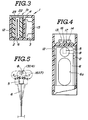
- Figs. 1 to 7 show an embodiment of the present invention.
- the interior of an elongate retangular cross- section non-magnetic casing 1 is partitioned into first and second sections 2, 3 by a partition wall 4.
- a permanent magnet 5 is disposed in the first of the two sections and supported on a flexible non-magnetic support member 6 which in this instance is made of a phosphor bronze of the like material.
- the member 6 in this embodiment takes the form of an essentially rectangular thin plate in which a large oval cut-out 6a is formed (see Fig. 4).
- the plate is arranged to be flexible in one direction (viz., in first and second opposite directions x and y - as shown schematically in Fig. 5).
- the poles (N,S) of the magnet 5 are alinged with the direction in which the member 6 is flexible.
- Weights 7 and 8 are attached to each face of the magnet 5 in a manner as shown in Fig. 2.
- the weights are formed of a non- magnetic material and are selected so that the combined mass of the weights and the magnet is of a value predetermined in view of the intended application of the device.
- the lower end (viz., the end distal from the magnet 5) of the flexible member 6 is embedded in a non-magnetic support 9 which can be sealingly inserted through an aperture formed in the lower end face of the casing 1 and project into the first section 2 of the casing 1.
- the support 9 is formed with two retangular cross-section finger-like extensions 10, 11 which flank the front and rear face of the support member 6.
- the first section 2 contains a damper oil 12. This fluid exhibits suitable viscosity and other physical properties suitable for damping excessively rapid motion of the pendulum like arrangement defined by the magnet 6, weights 7, 8, and flexible support member 6 and thus ensures stable operation of the device.
- First and second proximity sensors 13, 14 which in this embodiment take the form of linear type Hall-effect IC units are are disposed on the partition wall 4 in the second section 3 in a manner such as shown in Figs. 2 and 4.
- Each of these units has a respective Hall-effect element 16, 17 which are arranged in close proximity of the magnet in an essentially side-by-side manner.
- the elements 16 and 17 are arranged in a manner that when the magnet moves in the x direction for example the output of one element increases while the other decreases and vice versa.
- a differential amplifer circuit 15 is attached to an inner wall of the casing 1 in a manner to be spaced from the partition wall 4. This circuit provides an operative interconnection between the proximity sensors and a control circuit not shown such as that used to control an anti-skid control system, suspension or the like.
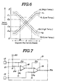
- Fig. 6 shows in graphical form the output characteristics of the two proximity sensors 13, 14 and the effect of temperature thereon.
- the sensors 13, 14 are arranged so that when the magnet 5 assumes a neutral position the outputs of the two sensors are equal. In Fig. 6 this situation is shown by the intersection of the traces al (sensor 13) and a2 (sensor 14) at a magnetic flux density denoted by "0".
- the instant device is constructed so that the maximum possible displacement of the magnet is limited in a manner, which as shown in Fig. 5, is such that the effective magnetic field (phi) generated by magnet 5 does not move to the point that the output of either sensor becomes constant. This ensures accurate metering even when the flexible member 6 is subject to maximum deflection.
- the difference between the two outputs for any change in magnetic field intensity is constant irrespective of the drift in output caused by changes in temperature while the magnitude of the difference indicative of the acceleration to which the mass (magnet and weights) are subject.
- the outputs of sensors 13 and 14 are E1 and E3 respectively, while under relatively low temperature conditions the corresponding outputs are E2 and E4.
- the magnitude of E1 - E3 and the magnitude of E2 - E4 are the same.
- Fig. 7 shows an example of a circuit arrangement which can be used to detect the difference between the outputs of the two Hall-effect units 13, 14 and generate a signal indicative of the acceleration to which the magnet 5 is subject.
- This circuit includes two differential amplifiers 18, 19. The first of these units is operatively connected with the Hall-effect IC 13 and a source of power 20.
- a variable resistor 21 is arranged between the current source 20 and connected with the inverting input (-) of differential amplifier 18 through a pickup 21a.
- the non- inverting input (+) of this device is connected to ground through a first pulldown resistor R1.
- the output of differential amplifier 18 is connected to its own inverting input (-) via resistor R2 and to the non-inverting input (+) of the second amplifer 19.
- the inverting input (-) of the second amplifier 19 is connected to the second sensor 14 and to ground through a pulldown resistor R3.
- the output of the second amplifer 19 is connected to its own non-inverting input (+) via
- a lamp 28 is disposed in an upper corner of the 1b face of the casing 1. This lamp 28 is operatively connected with the differential amplifier circuit 15 in a manner that it becomes illuminated when a balance between the outputs of the two proximity sensors 13, 14 is achieved. This of course facilitates adjustment of variable resistor 21 in that it is possible to visually detect the situation wherein a balance has been achieved between the outputs of the two proximity sensors and a zero output appears on terminal 15a.
- the casing 1 of the instant embodiment is formed with an inspection window 22 in side denoted by 1b in Fig. 1. This window is closed by a transparent or semi-transparent panel 23. Two level markers 24 and 25 are formed at the periphery of the window 22. By using these markers it is possible to determine by visual inspection if the appropriate amount of air is present.
- the air bubble 26 and the marker 24 act as a "spirit level" or level gauge which is used for setting the accelerometer in place when it is to be used for lateral and forward directional sensing while the marker 25 and the bubble are used when the device is to be disposed horizontally for sensing vertical acceleration.
Landscapes
- Physics & Mathematics (AREA)
- General Physics & Mathematics (AREA)
- Measurement Of Length, Angles, Or The Like Using Electric Or Magnetic Means (AREA)
- Transmission And Conversion Of Sensor Element Output (AREA)
Description
- The present invention relates to an accelerometer and more specifically to an accelerometer for use in an automotive vehicle or the like and which exhibits an arrangement whereby temperature compensation can be effected without the need of a temperature sensor and associated complex circuitry.
- In order to control modern suspensions and the like type of automotive apparatus in a manner which ensures safe stable operation it is necessary to sense the level of acceleration that the vehicle is being subject to in vertical (up and down) and lateral (left and right) directions as well as the direction (fore-aft) in which the vehicle is travelling. To accomplish this it is known to use one or more accelerometers of the type disclosed in Japanese Provisional Patent Publication No. 52- 49871. The device disclosed in this document includes a permanent magnet which is suspended in a manner that it can be displaced in one of the above mentioned vertical, lateral or for- aft directions of the vehicle; and a Hall-effect Hall IC which disposed proximate the magnet in a manner to be responsive to the movement thereof.
- However, the arrangement while being simple has suffered from the drawback that the Hall IC is susceptible to temperature variation in a manner that the level of output thereof varies unacceptably. In order to compensate for this it has been proposed to include a temperature sensor arrangement in the IC which corrects the output level. However this not only complicates the circuitry but increases the size, weight and cost of the device.
- Further relevant prior art is disclosed in the FR-A-2366683. The known device includes first and second proximity sensors. It also contains a magnet supported by a flexible member and moveable in first and second opposite directions. One feature of this known device is a temperature compensation by means of complementarily varying sensor outputs plus measurement of the difference of these outputs.
- It is an object of the present invention to provide an accelerometer of the above mentioned kind wherein the casing is partitioned into first and second sections and which accelerometer is arranged to exhibit temperature compensation.
- This object is achieved by the features of claim 1.
- An advantage of the present invention is the provision of an acceleration sensor arrangement which is arranged to exhibit temperature compensation without the need to resort to the provision of the temperature sensor and associated complex circuitry.
- In order to achieve the above object first and second Hall-effect or the like type proximity sensors are arranged in combination with a magnet so that when the magnet is moved under the influence of an accelerative force or the like the output of one sensor increases while the other decreases. The magnitude of the difference between the two outputs is indicative of the force while the effects of temperature on the individual signals mutually offset one and other providing temperature compensation. The magnet is mounted in a pendulum-like arrangement wherein the magnet is supported in a balanced fashion by a single flexible member, causing the magnet to move in the first and second directions with a slightly arcuate path, the increase and decrease in the output of the first and second sensors being substantially proportional to their distance from the magnet.
- More specifically, the present invention takes the form of an accelerometer which features a first proximity sensor disposed in a casing; a second proximity sensor disposed in a casing close to the first one; a magnet movably supported within the casing by a flexible member so as be movable from a neutral position in a first and second opposite directions, the first and second proximity sensors being arranged so that when the magnet is moved in the first direction the output of the first sensor increases and the second sensor decreases and when the magnet moves in the second direction the output of the second sensor increases and the output of the first one decreases.
-
- Fig. 1 is a perspective view of an accelerometer according to the present invention;
- Fig. 2 is a sectional front elevation taken along section line II - II of Fig. 1;
- Fig. 3 is a sectional plan as taken along section line III - III of Fig. 2;
- Fig. 4 is a sectional side elevation taken along section line IV - IV of Fig. 2;
- Fig. 5 is a schematic elevation showing the fundamental arrangement of the present invention;
- Fig. 6 is a graph in terms of (a) the output of the Hall- effect sensor arrangement utilized in the present invention and (b) the displacement of the permanent magnet from a neutral or home position assumed when not subject to acceleration, the mutual cancellation effect which characterizes the present invention; and
- Fig. 7 is a circuit diagram showing a circuit arrangement utilized in the disclosed embodiment of the instant invention.
- Figs. 1 to 7 show an embodiment of the present invention. In this arrangement the interior of an elongate retangular cross- section non-magnetic casing 1 is partitioned into first and
second sections partition wall 4. Apermanent magnet 5 is disposed in the first of the two sections and supported on a flexiblenon-magnetic support member 6 which in this instance is made of a phosphor bronze of the like material. Themember 6 in this embodiment takes the form of an essentially rectangular thin plate in which a large oval cut-out 6a is formed (see Fig. 4). The plate is arranged to be flexible in one direction (viz., in first and second opposite directions x and y - as shown schematically in Fig. 5). The poles (N,S) of themagnet 5 are alinged with the direction in which themember 6 is flexible.Weights magnet 5 in a manner as shown in Fig. 2. The weights are formed of a non- magnetic material and are selected so that the combined mass of the weights and the magnet is of a value predetermined in view of the intended application of the device. - To facilitate easy production and assembly of the device the lower end (viz., the end distal from the magnet 5) of the
flexible member 6 is embedded in a non-magnetic support 9 which can be sealingly inserted through an aperture formed in the lower end face of the casing 1 and project into thefirst section 2 of the casing 1. In this embodiment the support 9 is formed with two retangular cross-section finger-like extensions 10, 11 which flank the front and rear face of thesupport member 6. Thefirst section 2 contains adamper oil 12. This fluid exhibits suitable viscosity and other physical properties suitable for damping excessively rapid motion of the pendulum like arrangement defined by themagnet 6,weights flexible support member 6 and thus ensures stable operation of the device. - First and
second proximity sensors partition wall 4 in thesecond section 3 in a manner such as shown in Figs. 2 and 4. Each of these units has a respective Hall-effect element elements - A
differential amplifer circuit 15 is attached to an inner wall of the casing 1 in a manner to be spaced from thepartition wall 4. This circuit provides an operative interconnection between the proximity sensors and a control circuit not shown such as that used to control an anti-skid control system, suspension or the like. - Fig. 6 shows in graphical form the output characteristics of the two
proximity sensors sensors magnet 5 assumes a neutral position the outputs of the two sensors are equal. In Fig. 6 this situation is shown by the intersection of the traces al (sensor 13) and a2 (sensor 14) at a magnetic flux density denoted by "0". However, when themagnet 5 is moved under the influence of accelerative forces the output of one increases while the output of the other decreases. Upon themagnet 5 being displaced by more than a predetermined amount the output of the sensors tends to become constant. Accordingly, the instant device is constructed so that the maximum possible displacement of the magnet is limited in a manner, which as shown in Fig. 5, is such that the effective magnetic field (phi) generated bymagnet 5 does not move to the point that the output of either sensor becomes constant. This ensures accurate metering even when theflexible member 6 is subject to maximum deflection. - As will be appreciated with the present invention, when the
magnet 5 is displaced, the difference between the two outputs for any change in magnetic field intensity is constant irrespective of the drift in output caused by changes in temperature while the magnitude of the difference indicative of the acceleration to which the mass (magnet and weights) are subject. For example, under relatively high temperature conditions for a deflection which changes the magnetic field to point B1, the outputs ofsensors - Fig. 7 shows an example of a circuit arrangement which can be used to detect the difference between the outputs of the two Hall-
effect units magnet 5 is subject. This circuit includes twodifferential amplifiers effect IC 13 and a source ofpower 20. Avariable resistor 21 is arranged between thecurrent source 20 and connected with the inverting input (-) ofdifferential amplifier 18 through a pickup 21a. The non- inverting input (+) of this device is connected to ground through a first pulldown resistor R1. The output ofdifferential amplifier 18 is connected to its own inverting input (-) via resistor R2 and to the non-inverting input (+) of thesecond amplifer 19. The inverting input (-) of thesecond amplifier 19 is connected to thesecond sensor 14 and to ground through a pulldown resistor R3. The output of thesecond amplifer 19 is connected to its own non-inverting input (+) via resistor R4. - A
lamp 28 is disposed in an upper corner of the 1b face of the casing 1. Thislamp 28 is operatively connected with thedifferential amplifier circuit 15 in a manner that it becomes illuminated when a balance between the outputs of the twoproximity sensors variable resistor 21 in that it is possible to visually detect the situation wherein a balance has been achieved between the outputs of the two proximity sensors and a zero output appears on terminal 15a. - As the
first section 2 of the casing 1 containsdamper oil 12 it is necessary to allow for its thermal expansion by providing an air space of controlled volume therein (an air bubble). For this purpose the casing 1 of the instant embodiment is formed with aninspection window 22 in side denoted by 1b in Fig. 1. This window is closed by a transparent orsemi-transparent panel 23. Twolevel markers window 22. By using these markers it is possible to determine by visual inspection if the appropriate amount of air is present. Further, as will be noted, theair bubble 26 and themarker 24 act as a "spirit level" or level gauge which is used for setting the accelerometer in place when it is to be used for lateral and forward directional sensing while themarker 25 and the bubble are used when the device is to be disposed horizontally for sensing vertical acceleration. - Alternatively, it is possible to provide a separate level gauge arrangement such as denoted by the numerals 29 - 31 in Fig. 1 if so desired.
- It will be noted that although disclosure has been made with reference to Hall-effect type sensors it will be appreciated that other types of sensors such as magnetic resistance effect types can be used without departing from the scope of the present invention as defined in the appended claims.
Claims (11)
- An accelerometer wherein a first proximity sensor (13) disposed in a casing (1) and a second proximity sensor (14) is disposed proximate the first proximity sensor (13) the accelerometer also having a magnet (5) movably supported in the casing (1) so as to be movable, from a neutral position, in first (x) and second (y) opposite directions so that when the magnet (5) moves in the first direction (x) the output of the first sensor (13) increases and that of the second sensor (14) decreases and when the magnet (5) moves in the second direction (y) the output of the second sensor (14) increases and that of the first sensor (13) decreases,
characterized in that
the increase and decrease in the output of the first and second sensors (13,14) being substantially proportional to the displacement of the magnet (5) from said neutral position, said casing includes a wall portion (4) which hermetically divides the interior of the casing into first and second sections (2,3) wherein said magnet (5) and the flexible member (6) on which the magnet is supported is disposed in the first section (2) and wherein the first and second sensors (13,14) are disposed in said second section (3). - An accelerometer as claimed in claim 1, further having a circuit (15) responsive to the outputs of said first and second sensors (13,14) in a manner that the difference between their outputs is determined and used as a measure of the accelerative force to which the magnet (5) is subject.
- An accelerometer as claimed in claim 1 or 2, wherein said first section (2) chamber contains a damping fluid which exerts a damping effect on the movement of said magnet (5).
- An accelerometer as claimed in claim 1, wherein said flexible member (6) is mounted on a member (9) separate from said casing (1), said separate member (9) being sealingly disposed in an aperture formed in said casing (1).
- An accelerometer as claimed in claim 2, further comprising an illumination device (28) disposed in said casing (1), said illumination device (28) being operatively connected with said circuit (15) in a manner to become illuminated when the signals from said first and second proximity sensors (13,14) are balanced to the point that the difference therebetween is zero.
- An accelerometer as claimed in one of the preceding claims, wherein the first and second sensors (13,14) are connected in parallel.
- An accelerometer as set forth in anyone of the preceding claims, wherein said sensors (13,14) have a pair of Hall effect transducers (16,17).
- An accelerometer as set forth in claim 7, further including an attenuation means (21) for attenuating the output of one (13) of said Hall effect transducers so as to make the respective outputs of said pair of Hall effect transducers (16,17) mutually equal.
- An accelerometer as set forth in any of the preceding claims, wherein said magnet (5) is disposed within said first section (2) and a liquid damping fluid (12) is provided about said magnet, a bubble (26) being provided in said liquid damping fluid (12) for allowing for temperature dependent fluctuation in the volume of said liquid damping fluid.
- An accelerometer as set forth in claim 9, wherein a light conducting portion (22,24,26) is formed at a portion of said first section (21) through which light conducting portion the position and size of said bubble may be discerned for determining the orientation of said first section and the level of said damping fluid.
- An accelerometer as set forth in claim 9, wherein said flexible member (6) is provided on a sealing member (9) separate from said first section (2), said sealing member (9) being received in an aperture in said chamber for forming a liquid seal.
Applications Claiming Priority (2)
| Application Number | Priority Date | Filing Date | Title |
|---|---|---|---|
| JP61144472A JPS631975A (en) | 1986-06-20 | 1986-06-20 | Acceleration sensor |
| JP144472/86 | 1986-06-20 |
Publications (2)
| Publication Number | Publication Date |
|---|---|
| EP0251069A1 EP0251069A1 (en) | 1988-01-07 |
| EP0251069B1 true EP0251069B1 (en) | 1992-09-02 |
Family
ID=15363085
Family Applications (1)
| Application Number | Title | Priority Date | Filing Date |
|---|---|---|---|
| EP87108798A Expired EP0251069B1 (en) | 1986-06-20 | 1987-06-19 | Accelerometer |
Country Status (4)
| Country | Link |
|---|---|
| US (1) | US4870864A (en) |
| EP (1) | EP0251069B1 (en) |
| JP (1) | JPS631975A (en) |
| DE (1) | DE3781472T2 (en) |
Families Citing this family (21)
| Publication number | Priority date | Publication date | Assignee | Title |
|---|---|---|---|---|
| JPH0195667U (en) * | 1987-12-18 | 1989-06-23 | ||
| DE3929082A1 (en) * | 1988-12-09 | 1990-06-13 | Teves Gmbh Alfred | ACCELERATION SENSOR WITH SINGLE-SIDED CLAMP |
| JPH03253440A (en) * | 1990-03-01 | 1991-11-12 | Zexel Corp | Control system for vehicle safety device |
| DE4033885A1 (en) * | 1990-10-25 | 1992-04-30 | Bosch Gmbh Robert | ACCELERATION SENSOR |
| DE4036224A1 (en) * | 1990-11-14 | 1992-05-21 | Bosch Gmbh Robert | SENSOR |
| GB2284482A (en) * | 1993-12-02 | 1995-06-07 | Klippan Autoliv Snc | Improvements in or relating to an accelerometer |
| US5627315A (en) * | 1995-04-18 | 1997-05-06 | Honeywell Inc. | Accelerometer with a cantilever beam formed as part of the housing structure |
| US5670876A (en) * | 1995-11-14 | 1997-09-23 | Fisher Controls International, Inc. | Magnetic displacement sensor including first and second flux paths wherein the first path has a fixed reluctance and a sensor disposed therein |
| JP3719566B2 (en) * | 1996-05-27 | 2005-11-24 | 株式会社デンソー | solenoid valve |
| US6050160A (en) * | 1996-09-04 | 2000-04-18 | Joseph B. Willey | Apparatus and method for automatically compensating for lateral runout |
| US6101911A (en) * | 1996-09-04 | 2000-08-15 | Joseph B. Willey | Apparatus and method for automatically compensating for lateral runout |
| JPH10267685A (en) * | 1997-03-21 | 1998-10-09 | Unisia Jecs Corp | Vehicle side slip angle estimation method |
| US6515474B1 (en) | 1997-08-06 | 2003-02-04 | Fisher-Rosemount Systems, Inc. | Linearized magnetic displacement sensor |
| US6060881A (en) * | 1997-08-06 | 2000-05-09 | Fisher Controls International, Inc. | Flux shaping pole pieces for a magnetic displacement sensor |
| US6536469B2 (en) | 1999-06-29 | 2003-03-25 | Fisher Controls International, Inc. | Self-centering magnet assembly for use in a linear travel measurement device |
| US6909281B2 (en) | 2002-07-03 | 2005-06-21 | Fisher Controls International Llc | Position sensor using a compound magnetic flux source |
| ATE472093T1 (en) * | 2003-02-21 | 2010-07-15 | Fisher Controls Int | MAGNETIC POSITION SENSOR WITH INTEGRATED HALL EFFECT SWITCH |
| KR100632458B1 (en) | 2004-04-30 | 2006-10-11 | 아이치 세이코우 가부시키가이샤 | Accelerometer |
| US7536935B2 (en) * | 2005-04-07 | 2009-05-26 | Pro-Cut Licensing Company, Llc | Brake rotor resurfacing |
| JP4692605B2 (en) * | 2008-10-27 | 2011-06-01 | ブラザー工業株式会社 | Portable device |
| CN111505338B (en) * | 2020-05-03 | 2021-07-02 | 华中科技大学 | A magnetic feedback closed-loop acceleration sensor and its temperature compensation method |
Family Cites Families (9)
| Publication number | Priority date | Publication date | Assignee | Title |
|---|---|---|---|---|
| US2987669A (en) * | 1959-01-19 | 1961-06-06 | Gulton Ind Inc | Hall effect electromechanical sensing device |
| US3431417A (en) * | 1966-12-29 | 1969-03-04 | Industrial Nucleonics Corp | Energy reflection apparatus for measuring a physical variable |
| US3557628A (en) * | 1967-12-27 | 1971-01-26 | Toyoda Chuo Kenkyusho Kk | Accelerometer |
| JPS577389B2 (en) * | 1972-06-30 | 1982-02-10 | ||
| US3961185A (en) * | 1974-11-11 | 1976-06-01 | The Detroit Edison Company | Fiber optic displacement transducer |
| JPS5249871A (en) * | 1975-10-18 | 1977-04-21 | Toyota Motor Corp | Device for detecting deceleration for vehicles |
| DE2644606A1 (en) * | 1976-10-02 | 1978-04-06 | Daimler Benz Ag | MAGNETIC ACTUATED ELECTRIC SWITCH |
| DE2709156A1 (en) * | 1977-03-03 | 1978-09-07 | Vdo Schindling | Acceleration indicator device generating electrical signals - has Hall generator or field plate mounted adjacent deflectable permanent magnet |
| DE2829425C3 (en) * | 1978-07-05 | 1981-08-06 | Deutsche Forschungs- und Versuchsanstalt für Luft- und Raumfahrt e.V., 5000 Köln | Device for measuring accelerations on vibrating bodies |
-
1986
- 1986-06-20 JP JP61144472A patent/JPS631975A/en active Pending
-
1987
- 1987-06-17 US US07/063,263 patent/US4870864A/en not_active Expired - Fee Related
- 1987-06-19 EP EP87108798A patent/EP0251069B1/en not_active Expired
- 1987-06-19 DE DE8787108798T patent/DE3781472T2/en not_active Expired - Fee Related
Also Published As
| Publication number | Publication date |
|---|---|
| DE3781472T2 (en) | 1993-02-04 |
| EP0251069A1 (en) | 1988-01-07 |
| DE3781472D1 (en) | 1992-10-08 |
| US4870864A (en) | 1989-10-03 |
| JPS631975A (en) | 1988-01-06 |
Similar Documents
| Publication | Publication Date | Title |
|---|---|---|
| EP0251069B1 (en) | Accelerometer | |
| US4821218A (en) | Method and apparatus for determining at least one characteristic value of movement of a body | |
| EP0323709B1 (en) | Tri-axial accelerometers | |
| US5632093A (en) | Inductive sensor and method for detecting displacement of a body | |
| JPS6326520A (en) | Inclination sensor | |
| US4901571A (en) | Acceleration pickup | |
| US5524488A (en) | Flux control groove | |
| JPS59107205A (en) | Tilt angle sensor | |
| GB2087082A (en) | Electrically testing for straightness and evenness | |
| US3978715A (en) | Low frequency, high sensitivity electromechanical transducer | |
| SU727992A1 (en) | Device for determining moving object inclination angles | |
| SU1700484A1 (en) | Device for measurement of accelerations | |
| JPS63163209A (en) | Acceleration sensor | |
| US2820303A (en) | Integrating turn indicator | |
| SU1067445A1 (en) | Compensation accelerometer | |
| SU1115002A1 (en) | Gravitational variometer | |
| RU2046345C1 (en) | Accelerometer | |
| RU2065572C1 (en) | Device determining inclination angle of mobile object | |
| SU1099302A1 (en) | Gravimeter | |
| US2663088A (en) | Pendulum and acceleration compensation system | |
| SU390357A1 (en) | BUSSOL FOR DETERMINATION OF DEVIATION OF COURSE SYSTEMS AND COMPACES | |
| RU1812427C (en) | Inclination meter | |
| SU1040425A1 (en) | Float-type pendulum acceleration method | |
| SU1087944A1 (en) | Inclination meter | |
| SU558152A1 (en) | The device for determining the spatial position of the object |
Legal Events
| Date | Code | Title | Description |
|---|---|---|---|
| PUAI | Public reference made under article 153(3) epc to a published international application that has entered the european phase |
Free format text: ORIGINAL CODE: 0009012 |
|
| AK | Designated contracting states |
Kind code of ref document: A1 Designated state(s): DE FR GB |
|
| 17P | Request for examination filed |
Effective date: 19880628 |
|
| 17Q | First examination report despatched |
Effective date: 19891201 |
|
| RAP1 | Party data changed (applicant data changed or rights of an application transferred) |
Owner name: ATSUGI UNISIA CORPORATION |
|
| GRAA | (expected) grant |
Free format text: ORIGINAL CODE: 0009210 |
|
| AK | Designated contracting states |
Kind code of ref document: B1 Designated state(s): DE FR GB |
|
| REF | Corresponds to: |
Ref document number: 3781472 Country of ref document: DE Date of ref document: 19921008 |
|
| ET | Fr: translation filed | ||
| PLBE | No opposition filed within time limit |
Free format text: ORIGINAL CODE: 0009261 |
|
| STAA | Information on the status of an ep patent application or granted ep patent |
Free format text: STATUS: NO OPPOSITION FILED WITHIN TIME LIMIT |
|
| 26N | No opposition filed | ||
| PGFP | Annual fee paid to national office [announced via postgrant information from national office to epo] |
Ref country code: GB Payment date: 19970605 Year of fee payment: 11 |
|
| PGFP | Annual fee paid to national office [announced via postgrant information from national office to epo] |
Ref country code: FR Payment date: 19970616 Year of fee payment: 11 |
|
| PGFP | Annual fee paid to national office [announced via postgrant information from national office to epo] |
Ref country code: DE Payment date: 19970829 Year of fee payment: 11 |
|
| PG25 | Lapsed in a contracting state [announced via postgrant information from national office to epo] |
Ref country code: GB Free format text: LAPSE BECAUSE OF NON-PAYMENT OF DUE FEES Effective date: 19980619 |
|
| GBPC | Gb: european patent ceased through non-payment of renewal fee |
Effective date: 19980619 |
|
| PG25 | Lapsed in a contracting state [announced via postgrant information from national office to epo] |
Ref country code: FR Free format text: LAPSE BECAUSE OF NON-PAYMENT OF DUE FEES Effective date: 19990226 |
|
| PG25 | Lapsed in a contracting state [announced via postgrant information from national office to epo] |
Ref country code: DE Free format text: LAPSE BECAUSE OF NON-PAYMENT OF DUE FEES Effective date: 19990401 |
|
| REG | Reference to a national code |
Ref country code: FR Ref legal event code: ST |