EP0250699A2 - Flywheel - Google Patents
Flywheel Download PDFInfo
- Publication number
- EP0250699A2 EP0250699A2 EP87100895A EP87100895A EP0250699A2 EP 0250699 A2 EP0250699 A2 EP 0250699A2 EP 87100895 A EP87100895 A EP 87100895A EP 87100895 A EP87100895 A EP 87100895A EP 0250699 A2 EP0250699 A2 EP 0250699A2
- Authority
- EP
- European Patent Office
- Prior art keywords
- flywheel
- spring
- ring
- flywheel according
- damping
- Prior art date
- Legal status (The legal status is an assumption and is not a legal conclusion. Google has not performed a legal analysis and makes no representation as to the accuracy of the status listed.)
- Granted
Links
Images


Classifications
-
- F—MECHANICAL ENGINEERING; LIGHTING; HEATING; WEAPONS; BLASTING
- F16—ENGINEERING ELEMENTS AND UNITS; GENERAL MEASURES FOR PRODUCING AND MAINTAINING EFFECTIVE FUNCTIONING OF MACHINES OR INSTALLATIONS; THERMAL INSULATION IN GENERAL
- F16F—SPRINGS; SHOCK-ABSORBERS; MEANS FOR DAMPING VIBRATION
- F16F15/00—Suppression of vibrations in systems; Means or arrangements for avoiding or reducing out-of-balance forces, e.g. due to motion
- F16F15/10—Suppression of vibrations in rotating systems by making use of members moving with the system
- F16F15/16—Suppression of vibrations in rotating systems by making use of members moving with the system using a fluid or pasty material
- F16F15/167—Suppression of vibrations in rotating systems by making use of members moving with the system using a fluid or pasty material having an inertia member, e.g. ring
-
- F—MECHANICAL ENGINEERING; LIGHTING; HEATING; WEAPONS; BLASTING
- F16—ENGINEERING ELEMENTS AND UNITS; GENERAL MEASURES FOR PRODUCING AND MAINTAINING EFFECTIVE FUNCTIONING OF MACHINES OR INSTALLATIONS; THERMAL INSULATION IN GENERAL
- F16F—SPRINGS; SHOCK-ABSORBERS; MEANS FOR DAMPING VIBRATION
- F16F15/00—Suppression of vibrations in systems; Means or arrangements for avoiding or reducing out-of-balance forces, e.g. due to motion
- F16F15/10—Suppression of vibrations in rotating systems by making use of members moving with the system
- F16F15/12—Suppression of vibrations in rotating systems by making use of members moving with the system using elastic members or friction-damping members, e.g. between a rotating shaft and a gyratory mass mounted thereon
- F16F15/131—Suppression of vibrations in rotating systems by making use of members moving with the system using elastic members or friction-damping members, e.g. between a rotating shaft and a gyratory mass mounted thereon the rotating system comprising two or more gyratory masses
- F16F15/133—Suppression of vibrations in rotating systems by making use of members moving with the system using elastic members or friction-damping members, e.g. between a rotating shaft and a gyratory mass mounted thereon the rotating system comprising two or more gyratory masses using springs as elastic members, e.g. metallic springs
- F16F15/136—Plastics springs, e.g. made of rubber
Definitions
- the invention relates to a flywheel, comprising a first flywheel ring connected to the drive shaft and a second flywheel ring connected to the output shaft, which are relatively rotatably, concentrically mounted one inside the other, with a spring and a damping device for parallel between the first and second flywheel rings Suppression of torsional vibrations are provided.
- a flywheel of the aforementioned type is known from DE-OS 34 40 927.
- the damping device comprises two separate functional units which, depending on the size of the relative rotation of the two flywheels, are effective independently of one another and immediately following one another. The performance characteristics of the flywheel are still unsatisfactory.
- the invention has for its object to show a flywheel of the type mentioned, in which critical vibrations are largely excluded under normal operating conditions.
- the damping device When vibrations of a larger amplitude are introduced, the damping device is deactivated when the first angle dimension is exceeded. Only the spring is then effective, which leads to excellent isolation of corresponding vibrations due to the resilience of the spring. The vibrations can therefore no longer be disruptively transmitted via the flywheel.
- the springs and the damping devices are ring-shaped and concentrically assigned to the first and the second flywheel ring.
- the spring consists of rubber-elastic material.
- the material In contrast to metallic materials, the material has its own damping, which leads to a faster decay of high-frequency vibrations and to a certain relief of the actual damping device. It goes without saying that due to the considerable gradual difference in effectiveness, the inherent damping of rubber-elastic materials cannot replace the use of the additionally provided damping device.
- the spring connects holding surfaces of the first and second flywheel rings which surround one another radially.
- a particularly short axial length of the flywheel is achieved, which facilitates installation.
- a reduction in the diameter can be achieved by an embodiment according to claim 8, according to which it is provided that the spring connects axially opposite holding surfaces of the first and the second flywheel.
- the flywheels have a distance from the spring outside the holding surfaces. Any heat introduced is thereby kept away from the spring, which is of great importance in particular when using polymeric materials for their production with a view to achieving a good service life.
- the embodiment is further developed in claim 10, according to which it is provided that the cavity formed by the distance is sealed against the relatively rotatable flywheel and is filled with a liquid.
- a pressure builds up in the centrifugal force which, when properly designed, is suitable for largely eliminating or completely suppressing a deformation of the spring due to centrifugal force. This makes it easier to use the flywheel in applications where high speeds occur.
- the damping device can consist of a drive plate mounted on the first or the second flywheel ring. In addition to being particularly cost-effective to manufacture, particularly good stability is ensured in this case.
- the damping device consists of a concentric first friction disc of one flywheel ring and a concentric, second friction disc of the other flywheel ring, which are elastically pressed, the friction lining of the first and second friction discs only in the area corresponding to the first angular dimension provided and recessed between them.
- the friction linings on both sides disengage, as a result of which the two flywheels can easily be rotated against the force of the spring without any further frictional resistance alone.
- the friction discs on both sides can enclose each other radially. For reasons of ease of manufacture, preference is given to an embodiment in which the friction disks on both sides are axially assigned to one another and are accordingly axially pressed.
- the areas of relative torsional mobility, in which the two flywheels are connected in a springy and additionally damped manner, or only in a springy manner, can be delimited from one another as desired by the first angular dimension.
- An angle of ⁇ 30 ° should not be exceeded.
- a value of ⁇ 10 ° has proven to be advantageous, in the field of automotive engineering a value of ⁇ 5 °.
- the damping effect can be formed by a viscosity damper. Special embodiments are mentioned in claims 13 to 17. Thereafter, it is provided that the liquid contained in the cavity has a viscosity of 100 to 200,000 cSt, and that the damping device is formed by the liquid and the relatively movable surfaces of the spring and the first and / or the second flywheel wetted by it becomes. Your additional use in terms of avoiding centrifugal deformations of the spring in the sense of the explanations to claim 8 is therefore appropriate.
- the designs of viscosity dampers described in claims 13 to 16 are primarily characterized in that the relatively rotatable surfaces for forming the lost motion are provided with damping zones which can be passed past one another, the damping zones being less distant in the non-twisted state than in the twisted state, and the Damping zones are evenly distributed over the circumference.
- the difference in distance between the mutually opposite damping zones of the two flywheels is expediently considerable in the non-twisted state and in the twisted state and is different by at least a factor of 0.5.
- the mutually opposite damping zones are thus at a smaller distance from one another in the non-twisted state of the two flywheel rings than in the twisted state, as a result of which the resulting damping forces are substantially greater in the former case.
- Claim 15 refers to a corresponding embodiment. According to claim 16, it is provided that the greater distance between the damping zones merges smoothly into the other surfaces. Sudden changes in damping force, which under certain circumstances can result in a pulse-like excitation of the entire drive train of a motor vehicle, can be avoided in this way.
- the overall damping effect depends largely on the size of the surfaces wetted by the damping fluid on both sides.
- the flywheel shown in FIG. 1 in a half-section is intended for use between the engine and the transmission of a motor vehicle.
- the first flywheel ring 1 and the second flywheel ring 2 are rotatably supported by the bearing 3, concentrically one inside the other. They enclose an annular cavity in which the spring 6 is arranged.
- the spring 6 is of an annular shape and is made of rubber-elastic material. It is connected on the outside by vulcanization to the retaining ring 4, on the inside by vulcanization to the retaining ring 5.
- the retaining ring 4 is screwed to the second flywheel ring 2 with the interposition of an intermediate flange 17 and a thermal insulation disk 16, the retaining ring 5 to the first flywheel ring 1.
- the thermal barrier disk 16 is extended radially inward to the circular heat shield 12.
- the retaining ring 5 has an angular profile and, in the region that extends inward in the radial direction, has openings that are evenly distributed on the circumference and into which the axially projecting finger extensions 10 of the pressure ring 7 engage.
- the pressure ring 7 has, on the side facing away from the finger processes 10, segment-shaped elevations 20 which are evenly distributed over the circumference.
- the angle ring 11 is also provided with identically designed elevations, which are assigned to the aforementioned mirror images. The transition zones to the axially recessed peripheral surfaces of the pressure ring 7 and the angle ring 11 are each rounded.
- the drive plate 9 is arranged axially between the regions of the pressure ring 7 and the angle ring 11 which carry the projections 20. This rests together with the pressure ring 7 on a slide bearing of the angle ring 11 and is provided on both sides in the axial direction with the elevations 20 of the pressure ring 7 and the angle ring 11 associated with sliding linings 18, 19.
- the plate spring 8 causes a compression of the pressure ring 7, the drive plate 9 and the angle ring 11 in the axial direction.
- the angle ring 11 and the pressure ring 7 are non-rotatable with respect to one another and with respect to the first flywheel ring 1, the drive plate with respect to the second flywheel ring 2.
- the respective entrainment is brought about by a screw connection or finger extensions 10 which, while avoiding play in Engage in the circumferential direction in correspondingly designed recesses of the first and second flywheel rings 1, 2.
- the sliding linings 18, 19 arranged on the two axial boundary surfaces of the driving plate 9 are designed as ring segments and distributed alternately on the circumference of the driving plate 9. In the exemplary embodiment shown, they directly adjoin one another.
- the type 18 sliding pads and the type 19 sliding pads are all of the same size.
- the former 18 are formed by brake pads with a high coefficient of friction, the latter 19 by a material that has an extremely low coefficient of friction.
- the type 18 sliding pads on both sides are mirror images of each other. The same applies to the type 19 sliding pads.
- the driving plate 9 is assigned to the pressure ring 7 and the angle ring 11 in such a way that, in the static rest position of the torsional vibration damper, the greatest possible overlap between the sliding pads 18 formed by brake pads on the one hand and the projections on the other hand results.
- a relative rotation of the driving plate 9 with respect to the pressure ring 7 and the angle ring 11 therefore initially requires a considerable frictional resistance to be overcome, which is used in the context of the present invention for the increased damping of vibrations with a small torsional amplitude.
- the second flywheel ring 2 is provided in the region of its inner circumference with axial projections which engage in the spaces between the finger extensions 10. These cause the rotary movement to be transmitted to the finger extensions 10, as a result of which the damping device formed by the parts 5, 7, 8, 9 and 11 becomes increasingly ineffective after exceeding a certain minimum rotation of the first flywheel ring 1 with respect to the second flywheel ring 2 until the elevations 20, 21 of the pressure ring 7 and the angle ring 11 finally slide only on the pads with a lower coefficient of friction.
- the heat shield 12 fixed on the second flywheel ring 2 serves to isolate the spring 6, which is made of rubber-elastic material, against undesired heating.
- the spring 6 which is made of rubber-elastic material, has a circular shape and is fixed to the retaining surfaces of the first flywheel ring 1 and the second flywheel ring 2 that enclose one another in the radial direction.
- the spring 6 has an axial distance on both sides from the opposite boundary walls of the first flywheel ring 1, and the cavities formed in this way are dynamically sealed against the second flywheel ring 2 and filled with silicone oil with a viscosity of 100 to 200,000 cSt.
- the toothed disks 7 immersed in the cavities are wetted by the latter, which are fixed to the second flywheel ring 2 in the region of their inner circumference.
- the first flywheel ring 1 is provided with pocket-shaped recesses 22 which are assigned opposite to the spaces between the teeth of the toothed disks. A relative rotation of the first flywheel ring 1 with respect to the second flywheel ring 2, in addition to an elastic deformation of the spring 6, also results in a viscosity damping of the movement.
- the liquid-filled cavities delimiting the spring 6 in the axial direction on both sides are connected by the channel 13 arranged in the region of the outer circumference of the spring 6.
- the pressure increase resulting from a rotary movement in the two spaces is therefore completely balanced and ensures good mechanical support of the spring 6 against deformations caused by centrifugal force.
- the free space containing the liquid is limited to the outside in the radial direction and liquid-impermeable on both sides in the axial direction. Due to the annular distribution of the liquid volume contained when the shaft rotates, even in the radially inner region there is no need for a secondary seal if it is ensured that the liquid volume required for operation cannot escape when the shaft is at a standstill.
- the flywheel shown in Figure 4 is functionally similar to that described above.
- a viscosity damper is used in which the spring is only wetted on the outside by viscous liquid because of its attachment to holding surfaces of the first flywheel ring 1 and the second flywheel ring 2 that have an axial spacing.
- This fills the available space with the flywheel rotating up to about a third of the height of the radially inner boundary surface of the spring and thus prevents centrifugal deformations of the two outer springs.
- the liquid is therefore only contained in a single, self-contained cavity and, in contrast to the embodiment described above, a single sealing ring 14 is therefore sufficient for the dynamic sealing of this cavity.
- the spring 6 was divided into three rings enclosing one another in the radial direction in order to reduce the axial overall length.
- the cross-section of these is matched to one another in such a way that the cross-sectional load is the same in all three cases when the two flywheels are rotated relative to one another.
- a single material of certain flexibility is sufficient, which facilitates the production.
- FIGS. 5 to 8 are intended to illustrate the structure and mode of operation of viscosity dampers similar to Figures 3 and 4.
- the viscosity dampers are shown in FIGS. 5 and 7 in disassembled form, in FIGS. 6 and 8 in the mutual assignment resulting from the assembly.
- Both of the viscosity dampers shown comprise toothed disks 21 wetted by the viscous liquid, the teeth 23 of which, in the static rest position, have a small axial or radial distance from appropriately designed projections 24 of the relatively moving flywheel ring 1.
- the toothed disks 21 are non-rotatably fixed with respect to the stationary flywheel. Their teeth overlap the projections of the relatively movable flywheel in the static rest position with a small distance, it being functionally irrelevant whether the mutual assignment of the teeth to the projections is carried out in the axial direction, as shown in FIGS. 5 and 6 or in radial direction, as shown in Figures 7 and 8.
- the resulting damping effect can be adjusted to almost any characteristic by changing the mutual distance and the size of the facing surfaces of the teeth 23 and the projections 24 or by changing the viscosity of the liquid contained.
- a highly damped relative rotatability of ⁇ 10 ° has generally proven to be advantageous.
Abstract
Schwungrad, umfassend einen mit der Antriebswelle verbundenen ersten Schwungring (1) und einen mit der Abtriebswelle verbundenen zweiten Schwungring (2), die relativ verdrehbar und konzentrisch ineinander gelagert sind, wobei zwischen dem ersten und dem zweiten Schwungring parallel zueinander eine Feder (6) und eine Dämpfungseinrichtung (7, 8, 9, 11) zur Hemmung einer relativen Verdrehung vorgesehen sind, wobei nur die Dämpfungseinrichtung mit einem Totgang versehen ist, durch den ihre Dämpfungswirkung bei einer Relativverdrehung von mehr als 30° aufgehoben und die Feder (6) allein wirksam ist.Flywheel, comprising a first flywheel ring (1) connected to the drive shaft and a second flywheel ring (2) connected to the output shaft, which are relatively rotatably and concentrically mounted one inside the other, a spring (6) and a damping device (7, 8, 9, 11) is provided for inhibiting relative rotation, only the damping device being provided with a lost motion, by means of which its damping effect is canceled when the relative rotation is greater than 30 ° and the spring (6) alone is effective is.
Description
Die Erfindung betrifft ein Schwungrad, umfassend einen mit der Antriebswelle verbundenen, ersten Schwungring und einen mit der Abtriebswelle verbundenen, zweiten Schwungring, die relativ verdrehbar, konzentrisch ineinander gelagert sind, wobei zwischen dem ersten und dem zweiten Schwungring parallel zueinander eine Feder und eine Dämpfungseinrichtung zur Unterdrückung von Verdrehschwingungen vorgesehen sind.The invention relates to a flywheel, comprising a first flywheel ring connected to the drive shaft and a second flywheel ring connected to the output shaft, which are relatively rotatably, concentrically mounted one inside the other, with a spring and a damping device for parallel between the first and second flywheel rings Suppression of torsional vibrations are provided.
Ein Schwungrad der vorgenannten Art ist aus DE-OS 34 40 927 bekannt. Die Dämpfungseinrichtung umfaßt dabei zwei getrennte Funktionseinheiten, die in Abhängigkeit von der Größe der relativen Verdrehung der beiden Schwungringe unabhängig voneinander und unmittelbar aufeinander folgend wirksam sind. Die Gebrauchseigenschaften des Schwungrades sind noch wenig befriedigend.A flywheel of the aforementioned type is known from DE-OS 34 40 927. The damping device comprises two separate functional units which, depending on the size of the relative rotation of the two flywheels, are effective independently of one another and immediately following one another. The performance characteristics of the flywheel are still unsatisfactory.
Der Erfindung liegt die Aufgabe zugrunde, ein Schwungrad der eingangs genannten Art zu zeigen, bei dem bie Übertragung kritischer Schwingungen unter normalen Betriebsbedingungen weitgehend ausgeschlossen ist.The invention has for its object to show a flywheel of the type mentioned, in which critical vibrations are largely excluded under normal operating conditions.
Diese Aufgabe wird erfindungsgemäß durch die kennzeichnenden Merkmale von Anspruch 1 gelöst.This object is achieved according to the invention by the characterizing features of
Durch die erfindungsgemäß vorgeschlagene Ausbildung des Schwungrades werden Schwingungen im Bereich kleiner, die Nullage umschließender Winkelverdrehungen durch die zu der Feder parallel geschaltete Dämpfungseinrichtung hochgradig gedämpft. Die störende Übertragung solcher Schwingungen wird dadurch sicher vermieden, desgleichen die Gefahr des Auftretens von Resonanzschwingungen mit erhöhter Amplitude.Due to the design of the flywheel proposed according to the invention, vibrations in the region of small angular rotations enclosing the zero position are damped to a high degree by the damping device connected in parallel with the spring. The disruptive transmission of such vibrations is thus reliably avoided, as is the risk of resonance vibrations with increased amplitude.
Bei Einleitung von Schwingungen einer größeren Amplitude wird bei Überschreitung des ersten Winkelmaßes die Dämpfungseinrichtung außer Betrieb gesetzt. Es ist dann nur noch die Feder allein wirksam, was zu einer ausgezeichneten Isolierung entsprechender Schwingungen durch die Nachgiebigkeit der Feder führt. Die Schwingungen können daher nicht mehr störend über das Schwungrad übertragen werden.When vibrations of a larger amplitude are introduced, the damping device is deactivated when the first angle dimension is exceeded. Only the spring is then effective, which leads to excellent isolation of corresponding vibrations due to the resilience of the spring. The vibrations can therefore no longer be disruptively transmitted via the flywheel.
Zweckmäßige Weiterbildungen der Erfindung nach Anspruch 1 sind in den Unteransprüchen beschrieben.Advantageous developments of the invention according to
Bei der Ausgestaltung nach Anspruch 5 sind die Federn und die Dämpfungseinrichtungen ringförmig ausgebildet und dem ersten und dem zweiten Schwungring konzentrisch zugeordnet.In the embodiment according to
Eine Unwuchtigkeit wird hierdurch vermieden und erlaubt eine problemlose Verwendung des vorgeschlagenen Schwungrades in Antriebssträngen, in denen höchste Drehzahlen auftreten.This prevents an imbalance and allows the proposed flywheel to be used without problems in drive trains in which the highest speeds occur.
Nach Anspruch 6 ist es vorgesehen, daß die Feder aus gummielastischem Werkstoff besteht. Der Werkstoff weist im Gegensatz zu metallischen Werkstoffen eine Eigendämpfung auf, was zu einem schnelleren Abklingen hochfrequenter Schwingungen führt sowie zu einer gewissen Entlastung der eigentlichen Dämpfungseinrichtung. Es versteht sich von selbst, daß aufgrund des erheblichen graduellen Unterschiedes in der Wirksamkeit die Eigendämpfung gummielastischer Werkstoffe die Verwendung der zusätzlich vorgesehenen Dämpfungseinrichtung nicht ersetzen kann.According to
Bei der Ausgestaltung nach Anspruch 7 ist es vorgesehen, daß die Feder einander radial umschließende Halteflächen des ersten und des zweiten Schwungringes verbindet. Hierdurch wird eine besonders kurze axiale Baulänge des Schwungrades erreicht, was den Einbau erleichtert. Eine Verminderung des Durchmessers läßt sich demgegenüber erreichen durch eine Ausgestaltung entsprechend Anspruch 8, nach der es vorgesehen ist, daß die Feder einander axial gegenüberliegende Halteflächen des ersten und des zweiten Schwungrades verbindet.In the embodiment according to
Auch die praktische Anwendung von Mischformen zwischen beiden Ausführungen kann in die Überlegungen mit einbezogen werden, somit von Ausführungsformen, bei denen mindestens eine Feder an einander axial gegenüberliegenden Halteflächen des ersten und des zweiten Schwungringes festgelegt ist und mindestens eine weitere Feder an einander radial umschließenden Halteflächen des ersten und des zweiten Schwungringes. Die koaxiale Führung beider Schwungringe ineinander erfährt hierdurch eine Verbesserung.The practical application of mixed forms between the two designs can also be included in the considerations, thus of embodiments in which at least one spring is fixed on axially opposite holding surfaces of the first and the second flywheel ring and at least one further spring on radially surrounding holding surfaces of the first and second flywheel. The coaxial guidance of the two flywheels into one another is thereby improved.
Bei der Ausbildungsform nach Anspruch 9 ist vorgesehen, daß die Schwungringe außerhalb der Halteflächen einen Abstand von der Feder haben. Eventuell eingeleitete Wärme wird hierdurch von der Feder ferngehalten, was insbesondere bei der Verwendung von polymeren Werkstoffen zu deren Herstellung von großer Bedeutung ist in Hinblick auf die Erzielung einer guten Gebrauchsdauer.In the embodiment according to
Die Ausführungsform wird weitergebildet in Anspruch 10, wonach es vorgesehen ist, daß der durch den Abstand gebildete Hohlraum gegenüber dem relativ verdrehbaren Schwungring abgedichtet und mit einer Flüssigkeit gefüllt ist. In Abhängigkeit von der eingeleiteten Drehzahl baut sich in dieser fliehkraftbedingt ein Druck auf, der bei sachgerechter Auslegung geeignet ist, eine fliehkraftbedingte Deformierung der Feder weitgehend auszuschließen oder ganz zu unterdrükken. Die Verwendung des Schwungrades in Anwendungen, in denen hohe Drehzahlen auftreten, wird hierdurch erleichtert.The embodiment is further developed in
Die Dämpfungseinrichtung kann gemäß Ausgestaltung der Erfindung nach Anspruch 10 aus einer auf dem ersten oder dem zweiten Schwungring gelagerten Mitnehmerscheibe bestehen. Neben einer besonders kostengünstigen Herstellbarkeit ist in diesem Falle eine besonders gute Stabilität gewährleistet.According to an embodiment of the invention, the damping device can consist of a drive plate mounted on the first or the second flywheel ring. In addition to being particularly cost-effective to manufacture, particularly good stability is ensured in this case.
Es ist im Sinne der Erfindung vorgesehen, nur Schwingungen unterhalb einer gewissen Maximalamplitude in einem die statische Nullage unschließenden Bereich wirksam zu dämpfen. Die Ausgestaltung nach Anspruch 11 nimmt auf eine konstruktive Möglichkeit zur Erzielung dieses Effektes Bezug. Sie ist dadurch gekennzeichnet, daß die Dämpfungseinrichtung aus einer konzentrischen ersten Reibscheibe des einen Schwungringes und einer konzentrischen, zweiten Reibscheibe des anderen Schwungringes besteht, die elastisch verpreßt sind, wobei der Reibbelag der ersten und der zweiten Reibscheibe nur im Bereich von dem ersten Winkelmaß entsprechenden Sektoren vorgesehen und zwischen denselben ausgespart ist. Bei einer dieses Winkelmaß überschreitenden Verdrehung des ersten und des zweiten Schwungringes kommen die beiderseitigen Reibbeläge außer Eingriff, wodurch die beiden Schwungringe ohne jeden weiteren Reibungswiderstand allein gegen die Kraft der Feder leicht verdrehbar sind. Die beiderseitigen Reibscheiben können einander radial umschließen. Aus Gründen der einfachen Herstellbarkeit wird jedoch einer Ausführung der Vorzug gegeben, bei der die beiderseitigen Reibscheiben einander axial zugeordnet und dementsprechend axial verpreßt sind.It is provided in the sense of the invention to effectively dampen only vibrations below a certain maximum amplitude in a range that does not include the static zero position. The embodiment according to
Die Bereiche relativer Verdrehbeweglichkeit, in denen die beiden Schwungringe federnd und zusätzlich gedämpft verbunden sind, bzw. nur federnd, können durch das erste Winkelmaß beliebig gegeneinander abgegrenzt werden. Ein Winkelmaß von ± 30° soll nicht überschritten werden. Im allgemeinen Maschinenbau hat sich ein solches von ± 10° als vorteilhaft bewährt, im Bereich der Kfz.-Technik ein solches von ± 5°. Je nach Anwendungsgebiet gelingt es so in jedem Falle, eine optimale Unterdrückung störender Schwingungen im gesamten Frequenzbereich zu erzielen.The areas of relative torsional mobility, in which the two flywheels are connected in a springy and additionally damped manner, or only in a springy manner, can be delimited from one another as desired by the first angular dimension. An angle of ± 30 ° should not be exceeded. In general mechanical engineering, a value of ± 10 ° has proven to be advantageous, in the field of automotive engineering a value of ± 5 °. Depending on the field of application, it is possible to optimally suppress disturbing vibrations in the entire frequency range.
Die Dämpfungswirkung kann durch einen Viskositätsdämpfer gebildet werden. Spezielle Ausgestaltungsformen werden in den Ansprüchen 13 bis 17 erwähnt. Danach ist es vorgesehen, daß die in dem Hohlraum enthaltene Flüssigkeit eine Viskosität von 100 bis 200 000 cSt aufweist, und daß die Dämpfungseinrichtung durch die Flüssigkeit und die von dieser benetzten, relativ bewegbaren Flächen der Feder und des ersten und/oder des zweiten Schwungringes gebildet wird. Ihre zusätzliche Verwendung in Hinblich auf die Vermeidung fliehkraftbedinger Deformierungen der Feder im Sinne der Ausführungen zu Anspruch 8 bietet sich daher an.The damping effect can be formed by a viscosity damper. Special embodiments are mentioned in
Die in den Ansprüchen 13 bis 16 beschriebenen Ausführungen von Viskositätsdämpfern sind vor allem dadurch gekennzeichnet, daß die relativ verdrehbaren Flächen zur Bildung des Totganges mit aneinander vorbeiführbaren Dämpfungszonen versehen sind, wobei die Dämpfungszonen im nichtverdrehten Zustand einen kleineren Abstand haben als im verdrehten Zustand und wobei die Dämpfungszonen gleichmäßig auf dem Umfang verteilt sind. Zweckmäßigerweise ist der Abstandsunterschied zwischen den einander gegenüberliegenden Dämpfungszonen der beiden Schwungringe im nichtverdrehten Zustand und im verdrehten Zustand erheblich und wenigstens durch den Faktor 0,5 verschieden. Die einander gegenüberliegenden Dämpfungszonen haben somit im nichtverdrehten Zustand der beiden Schwungringe einen kleineren Abstand voneinander als im verdrehten Zustand, wodurch die resultierenden Dämpfungskräfte im erstgenannten Falle wesentlich größer sind.The designs of viscosity dampers described in
Verdrehschwingungen einer kleinen Amplitude in einem die statische Nullage umschließenden Bereich werden dadurch hochgradig gedämpft, während die Dämpfungswirkung bei Einleitung von Verdrehschwingungen bei Überschreitung des ersten Winkelmaßes je nach maßlicher Abstimmung vernachlässigbar gering ist. Auch bei dieser Ausbildung der Dämpfungseinrichtung resultiert damit eine differenzierte Wirksamkeit in bezug auf die Einleitung von Schwingungen unterschiedlicher Amplituden. Sie wird in diesem Falle jedoch unter Verzicht auf die Verwendung von verschleißbeanspruchten Präzisionsteilen erzielt, was unter dem Gesichtspunkt einer günstigen Herstellbarkeit sowie der Erzielung einer besonders langen Gebrauchsdauer von großem Vorteil ist.As a result, torsional vibrations of a small amplitude in a region surrounding the static zero position are damped to a high degree, while the damping effect upon initiation of torsional vibrations when the first angular dimension is exceeded is negligibly small, depending on the dimensional coordination. This design of the damping device also results in a differentiated effectiveness with regard to the introduction of vibrations of different amplitudes. In this case, however, it is achieved by dispensing with the use of precision parts subject to wear, which is of great advantage from the point of view of inexpensive manufacture and the achievement of a particularly long service life.
In einigen Anwendungsfällen hat es sich bewährt, wenn die unterschiedlich großen Abstände zwischen den einander gegenüberliegenden Dämpfungszonen ein- oder mehrfach abgestuft ineinander übergehen. Der Grad der erzielten Dämpfungswirkung sinkt in diesem Falle ab in Abhängigkeit von dem Grad der relativen Verdrehung beider Schwungringe, was beispielsweise bei einem plötzlichen Lastwechsel eines Motors der Fall ist.In some applications, it has proven useful if the differently large distances between the mutually opposite damping zones merge into one another in one or more steps. The degree of damping effect achieved in this case drops depending on the degree of relative rotation of the two flywheels, which is the case, for example, in the event of a sudden load change of an engine.
Anspruch 15 nimmt auf eine entsprechende Ausgestaltung Bezug. Nach Anspruch 16 ist es vorgesehen, daß der größere Abstand der Dämpfungszonen gleichmäßig in die übrigen Flächen übergeht. Stoßartige Dämpfungskraftänderungen, die unter Umständen eine impulsartige Anregung des gesamten Antriebsstranges eines Kraftfahrzeuges zur Folge haben können, lassen sich hierdurch vermeiden.Claim 15 refers to a corresponding embodiment. According to
Die insgesamt erzielte Dämpfungswirkung ist maßgeblich abhängig von der Größe der von der Dämpfungsflüssigkeit beiderseits benetzten Flächen.The overall damping effect depends largely on the size of the surfaces wetted by the damping fluid on both sides.
Diese lassen sich bei Bedarf vergrößern durch Anbringung wenigstens eines ringförmig vorspringenden Ansatzes an der Feder und/oder dem ersten oder dem zweiten Schwungring.If necessary, these can be increased by attaching at least one annular projecting projection to the spring and / or the first or the second flywheel ring.
Die Erfindung wird nachfolgend anhand der als Anlage beigefügten Zeichnung weiter erläutert. Es zeigen:
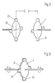
Figur 1 ein Schwungrad, bei dem die Mitnehmerscheibe mit Reibbelägen versehen ist und in Umfangsrichtung fest mit den Mitnehmern des sie lagernden Schwungrings verbunden ist.Figur 2 ein Schwungrad, bei dem die Feder zwischen einander radial umschließenden Halteflächen der Schwungringe angeordnet ist und bei der die Dämpfungseinrichtung aus einem Viskositätsdämpfer besteht.Figur 3 ein Ausführungähnlich Figur 2, bei der die Feder an einen axialen Abstand aufweisenden Halteflächen der Schwungringe festgelegt ist.- Figuren 4 bis 7 zwei Ausführungen von Viskositätsdämpfern in zerlegtem und montiertem Zustand, bei denen die aneinander vorbeiführbaren Dämpfungszonen im dargestellten, verdrehten Zustand beider Schwungringe einen größeren senkrechten Abstand voneinander haben als in dem unverdrehten Zustand gegenseitiger Überlappung. Im letztgenannten Falle ergibt sich eine relativ vergrößerte Dämpfungswirkung, die zu der Kraft der Feder parallel geschaltet ist.
- Figure 1 is a flywheel, in which the drive plate is provided with friction linings and is connected in the circumferential direction firmly to the drivers of the flywheel bearing it.
- Figure 2 is a flywheel, in which the spring is arranged between radially enclosing retaining surfaces of the flywheels and in which the damping device consists of a viscosity damper.
- Figure 3 shows an embodiment similar to Figure 2, in which the spring is fixed to an axially spaced holding surfaces of the flywheels.
- FIGS. 4 to 7 show two designs of viscosity dampers in the disassembled and assembled state, in which the damping zones which can be passed past one another in the illustrated, twisted state of the two flywheel rings are at a greater vertical distance from one another than in the untwisted state of mutual overlap. In the latter case, there is a relatively increased damping effect, which is connected in parallel to the force of the spring.
Das in Figur 1 in halbgeschnittener Darstellung wiedergegebene Schwungrad ist zur Verwendung zwischen dem Motor und dem Getriebe eines Kraftfahrzeuges bestimmt.The flywheel shown in FIG. 1 in a half-section is intended for use between the engine and the transmission of a motor vehicle.
Er umfaßt antriebsseitig den mit dem Anlasserritzel versehenen ersten Schwungring 1 und abtriebsseitig den nach dem Einbau die nicht dargestellte Kupplungsscheibe aufnehmenden zweiten Schwungring 2. Der erste Schwungring 1 und der zweite Schwungring 2 sind durch die Lagerung 3 relativ verdrehbar, konzentrisch ineinander gelagert. Sie umschließen einen kreisringförmigen Hohlraum, in dem die Feder 6 angeordnet ist.It comprises on the drive side the
Die Feder 6 ist von kreisringförmiger Gestalt und besteht aus gummielastischem Werkstoff. Sie ist außenseitig durch Vulkanisation mit dem Haltering 4 verbunden, innenseitig durch Vulkanisation mit dem Haltering 5. Der Haltering 4 ist unter Zwischenfügung eines Zwischenflansches 17 und einer Wärmedämmscheibe 16 mit dem zweiten Schwungring 2 verschraubt, der Haltering 5 mit dem ersten Schwungring 1. Die Wärmedämmscheibe 16 ist radial nach innen verlängert zu dem kreisförmig gestalteten Wärmeschirm 12.The
Der Haltering 5 ist von winkelförmigem Profil und weist in dem sich in radialer Richtung nach innen erstreckenden Bereich gleichmäßig auf dem Umfang verteilte Durchbrechungen auf, in welche die axial vorspringenden Fingerfortsätze 10 des Andrückringes 7 eingreifen. Der Andrückring 7 weist auf der von den Fingerfortsätzen 10 abgewandten Seite kreissegmentförmige Erhebungen 20 auf, die gleichmäßig auf dem Umfang verteilt sind. Mit identisch ausgebildeten Erhebungen, die den vorgenannten spiegelbildlich zugeordnet sind, ist auch der Winkelring 11 versehen. Die Übergangszonen zu den axial zurückspringenden Umfangsflächen des Andrückringes 7 und des Winkelringes 11 sind jeweils abgerundet ausgeführt.The retaining
Axial zwischen den die Vorsprünge 20 tragenden Bereichen des Andrückringes 7 und des Winkelringes 11 ist die Mitnehmerscheibe 9 angeordnet. Diese ruht gemeinsam mit dem Andrückring 7 auf einem Gleitlager des Winkelringes 11 und ist in axialer Richtung beiderseits mit den Erhebungen 20 des Andrückringes 7 und des Winkelringes 11 zugeordneten Gleitbelägen 18, 19 versehen. Die Tellerfeder 8 bewirkt eine gegenseite Verpressung des Andrückringes 7, der Mitnehmerscheibe 9 und des Winkelringes 11 in axialer Richtung. Der Winkelring 11 und der Andrückring 7 sind in bezug zueinander und in bezug zu dem ersten Schwungring 1 unverdrehbar, die Mitnehmerscheibe in bezug zu dem zweiten Schwungring 2. Die jeweilige Mitnahme wird durch eine Verschraubung bzw. Fingerfortsätze 10 bewirkt, die unter Vermeidung eines Spiels in Umfangsrichtung in entsprechend gestaltete Ausnehmungen des ersten und des zweiten Schwungringes 1, 2 eingreifen.The
Die auf den beiden axialen Begrenzungsflächen der Mitnehmerscheibe 9 angeordneten Gleitbeläge 18, 19 sind als Ringsegmente ausgebildet und abwechselnd auf dem Umfang der Mitnehmerscheibe 9 verteilt. Sie schließen bei dem gezeigten Ausführungsbeispiel unmittelbar aneinander an. Die Gleitbeläge vom Typ 18 und die Gleitbeläge vom Typ 19 sind jeweils alle von gleicher Größe. Die ersteren 18 werden durch Bremsbeläge mit hohem Reibungskoeffizienten gebildet, die letzteren 19, durch ein Material, das einen extrem niedrigen Reibungskoeffizienten aufweist. Die auf den beiden Seiten angeordneten Gleitbeläge vom Typ 18 sind einander spiegelbildlich zugeordnet. Das gleiche trifft zu in bezug auf die Gleitbeläge vom Typ 19.The sliding
Die Mitnehmerscheibe 9 ist dem Andrückring 7 und dem Winkelring 11 so zugeordnet, daß sich in der statischen Ruhelage des Drehschwingungsdämpfers eine möglichst weitgehende Überdeckung zwischen den durch Bremsbeläge gebildeten Gleitbelägen 18 einerseits und den Vorsprüngen andererseits ergibt.The driving
Eine Relativverdrehung der Mitnehmerscheibe 9 in bezug auf den Andrückring 7 und den Winkelring 11 erfordert daher zu Beginn die Überwindung eines erheblichen Reibungswiderstandes, was im Rahmen der vorliegenden Erfindung zur verstärkten Dämpfung von Schwingungen kleiner Verdrehamplitude genutzt wird.A relative rotation of the driving
Bei einer noch größeren Relativverdrehung zwischen der Mitnehmerscheibe 9 einerseits und dem Andrückring 7 und dem Winkelring 11 andererseits gelangen die Erhebungen 20 und die durch Bremsbeläge gebildeten Gleitbeläge 18 der Mitnehmerscheibe 9 zunehmend außer Deckung, was den Reibungswiderstand zunehmend vermindert. Die Dämpfungswirkung sinkt im gleichen Maße und verhindert das Auftreten von Reaktionskräften. Das Wirkungsprinzip ist in Figur 2 gezeigt.In the event of an even greater relative rotation between the driving
Der zweite Schwungring 2 ist im Bereich seines Innenumfanges mit in die Zwischenräume der Fingerfortsätze 10 eingreifenden, axialen Vorsprüngen versehen. Diese bewirken eine Übertragung der Drehbewegung auf die Fingerfortsätze 10, wodurch die durch die Teile 5, 7, 8, 9 und 11 gebildete Dämpfungseinrichtung nach Überschreiten einer bestimmten Mindestverdrehung des ersten Schwungringes 1 in bezug auf den zweiten Schwungring 2 zunehmend unwirksam wird, bis die Erhebungen 20, 21 des Andrückringes 7 und des Winkelringes 11 schließlich nur noch auf den Belägen mit geringerem Reibkoeffizienten gleiten. Der an dem zweiten Schwungring 2 festgelegte Wärmeschirm 12 dient der Isolierung der aus gummielastischem Werkstoff bestehenden Feder 6 gegen unerwünschte Erwärmung.The
Die in Figur 3 gezeigte Ausführung ist der vorstehend beschriebenen ähnlich. Auch in diesem Falle ist die aus gummielastischem Werkstoff bestehende Feder 6 von kreisringförmiger Gestalt und an einander in radialer Richtung umschließenden Halteflächen des ersten Schwungringes 1 und des zweiten Schwungringes 2 festgelegt.The embodiment shown in Figure 3 is similar to that described above. In this case too, the
Die Feder 6 hat beiderseits einen axialen Abstand von den gegenüberliegenden Begrenzungswänden des ersten Schwungringes 1, und die so gebildeten Hohlräume sind gegenüber dem zweiten Schwungring 2 dynamisch abgedichtet und mit Silikonöl der Viskosität von 100 bis 200 000 cSt gefüllt. Von diesem werden zugleich die in die Hohlräume eintauchenden Zahnscheiben 7 beiderseits benetzt, welche im Bereich ihres Innenumfanges an den zweiten Schwungring 2 festgelegt sind. Der erste Schwungring 1 ist mit taschenförmigen Ausnehmungen 22 versehen, die den Zwischenräumen der Zähne der Zahnscheiben gegenüberliegend zugeordnet sind. Eine relative Verdrehung des ersten Schwungringes 1 in bezug auf den zweiten Schwungring 2 hat dadurch neben einer elastischen Verformung der Feder 6 eine Viskositätsdämpfung der Bewegung zur Folge. Die die Feder 6 in axialer Richtung beiderseits begrenzenden, flüssigkeitsgefüllten Hohlräume stehen durch den im Bereich des Außenumfanges der Feder 6 angeordneten Kanal 13 in Verbindung. Die durch eine Drehbewegung in den beiden Räumen entstehende Drucksteigerung ist daher vollkommen ausgeglichen und gewährleistet eine gute mechanische Abstützung der Feder 6 gegen fliehkraftbedingte Deformierungen.The
Auch eine einseitige Wärmebeaufschlagung vermag die diesbezüglich guten Verhältnisse nicht zu verändern. Die Ausführung eignet sich daher für Anwendungsfälle, in denen höchste Belastungen auftreten.Even one-sided heat exposure cannot change the good conditions in this regard. The version is therefore suitable for applications in which the highest loads occur.
Am einfachsten lassen sich Verformungen der Feder 6 durch die Verwendung einer Flüssigkeit kompensieren, die dieselbe Dichte hat wie der Werkstoff der Feder. Entsprechende Flüssigkeiten sind bekannt. Ein Auffüllen des vorhandenen Freiraumes der sich drehenden Wellenkupplung bis zur radial inneren Begrenzungsfläche der Feder führt in diesem Falle zu vollem Erfolg.The easiest way to compensate for deformations of the
In Fällen, in denen die Feder eine größere Dichte aufweist als die Flüssigkeit, läßt sich ein entsprechendes Ergebnis erzielen durch eine entsprechend vergrößerte Überflutung der radialen Innenfläche der Feder bei sich drehender Wellenkupplung. Die Höhe der im Einzelfalle erforderlichen Überflutung läßt sich im Versuch exakt ermitteln oder auch errechnen. Ein besonderer Aufwand ist hinsichtlich der diesbezüglichen Feinarbeit jedoch in den meisten Fällen entbehrlich und zumindest teilweise durch Erfahrungswissen ersetzbar.In cases in which the spring has a greater density than the liquid, a corresponding result can be achieved by a correspondingly increased flooding of the radial inner surface of the spring when the shaft coupling rotates. The amount of flooding required in individual cases can be exactly determined or calculated in the experiment. With regard to the fine work in this regard, however, a special effort is in most cases unnecessary and can at least partially be replaced by experience.
Der die Flüssigkeit enthaltende Freiraum ist in radialer Richtung nach außen und in axialer Richtung beiderseits flüssigkeitsundurchlässig begrenzt. Er bedarf durch die ringförmige Verteilung des enthaltenen Flüssigkeitsvolumens bei sich drehender Welle auch in dem radial innenliegenden Bereich an sich keiner sekundären Abdichtung, wenn sichergestellt ist, daß das betriebsnotwendige Flüssigkeitsvolumen bei Wellenstillstand nicht entweichen kann.The free space containing the liquid is limited to the outside in the radial direction and liquid-impermeable on both sides in the axial direction. Due to the annular distribution of the liquid volume contained when the shaft rotates, even in the radially inner region there is no need for a secondary seal if it is ensured that the liquid volume required for operation cannot escape when the shaft is at a standstill.
Die Verwendung einer Dichtung zwischen den beiden Flanschen in dem genannten Bereich ist jedoch möglich und empfiehlt sich insbesondere dann, wenn die Einhaltung der vorgenannten Bedingung nicht möglich oder zu befürchten ist, daß sich während des normalen Betriebes der Wellenkupplung Fremdstoffe in den Freiraum einlagern. Insbesondere die Verwendung von Bewegungsdichtungen hat sich ausgezeichnet bewährt. Ihre Anbringung in anderen Zonen der Wellenkupplung ist ebenfalls möglich, erfordert jedoch eine spezielle Berücksichtigung des sich fliehkraftbedingt ergebenden Druckaufbaues in dem Freiraum. Eine Zuordnung zum Innendurchmesser der Wellenkupplung wird daher bevorzugt. Die Wirkung wird anhand der Figuren 5 und 6 erläutert.However, the use of a seal between the two flanges in the area mentioned is possible and is particularly recommended if compliance with the aforementioned condition is not possible or is to be feared that foreign substances will be stored in the free space during normal operation of the shaft coupling. In particular, the use of motion seals has proven to be excellent. Their attachment in other zones of the shaft coupling is also possible, but requires special consideration of the pressure build-up in the free space resulting from centrifugal force. An assignment to the inner diameter of the shaft coupling is therefore preferred. The effect is explained with reference to Figures 5 and 6.
Das in Figur 4 gezeigte Schwungrad ist funktionell dem vorstehend beschriebenen ähnlich. Auch in diesem Falle gelangt ein Viskositätsdämpfer zur Anwendung, bei dem die Feder wegen ihrer Festlegung an einen axialen Abstand aufweisenden Halteflächen des ersten Schwungringes 1 und des zweiten Schwungringes 2 indessen nur außenseitig von viskoser Flüssigkeit benetzt ist. Diese füllt den vorhandenen Freiraum bei sich drehendem Schwungrad bis etwa zu einem Drittel der Höhe der radial inneren Begrenzungsfläche der Feder aus und verhindert so fliehkraftbedingte Deformierungen der beiden äußeren Federn. Die Flüssigkeit ist daher nur in einem einzigen in sich geschlossenen Hohlraum enthalten und zur dynamischen Abdichtung dieses Hohlraumes genügt daher im Gegensatz zur vorstehend beschriebenen Ausführung ein einziger Dichtring 14.The flywheel shown in Figure 4 is functionally similar to that described above. In this case, too, a viscosity damper is used in which the spring is only wetted on the outside by viscous liquid because of its attachment to holding surfaces of the
Die Feder 6 wurde bei der Ausführung nach Figur 4 zur Reduzierung der axialen Baulänge in drei einander in radialer Richtung umschließende Ringe unterteilt. Diese sind hinsichtlich ihres Querschnittes so aufeinander abgestimmt, daß sich bei einer gegenseitigen Verdrehung der beiden Schwungringe in allen drei Fällen dieselbe Querschnittsbelastung ergibt. Für die Herstellung aller drei Ringe genügt daher ein einziger Werkstoff von bestimmter Nachgiebigkeit, was die Herstellung erleichtert.In the embodiment according to FIG. 4, the
Die Figuren 5 bis 8 sollen Aufbau und Wirkungsweise von Viskositätsdämpfern ähnlich Figur 3 und 4 verdeutlichen. Die Viskositätsdämpfer sind in den Figuren 5 und 7 in zerlegter Form dargestellt, in den Figuren 6 und 8 in der sich aus der Montage ergebenden, gegenseitigen Zuordnung.Figures 5 to 8 are intended to illustrate the structure and mode of operation of viscosity dampers similar to Figures 3 and 4. The viscosity dampers are shown in FIGS. 5 and 7 in disassembled form, in FIGS. 6 and 8 in the mutual assignment resulting from the assembly.
Beide gezeigten Viskositätsdämpfer umfassen von der viskosen Flüssigkeit benetzte Zahnscheiben 21, deren Zähne 23 in der statischen Ruhelage einen geringen axialen bzw. radialen Abstand von entsprechend ausgebildeten Vorsprüngen 24 des relativ bewegten Schwungringes 1 haben. Die Zahnscheiben 21 sind in bezug auf den ruhenden Schwungring unverdrehbar festgelegt. Ihre Zähne überlappen die Vorsprünge des relativ bewegbaren Schwungringes in der statischen Ruhelage mit geringem Abstand, wobei es funktionstechnisch ohne weitere Bedeutung ist, ob die gegenseitige Zuordnung der Zähne zu den Vorsprüngen in axialer Richtung vorgenommen wird, wie in den Figuren 5 und 6 gezeigt oder in radialer Richtung, wie in den Figuren 7 und 8 gezeigt. Auch andere gegenseitige Zuordnungen sind ohne weiteres möglich, und es ist lediglich entscheidend, daß sich in der statischen Ruhelage eine möglichst weitgehende Überdeckung der einander zugewandten Flächen der Zähne 23 und der Vorsprünge 24 ergibt. Die Zähne 23 sind bei Einleitung einer Relativverdrehung in geringem Abstand an den Vorsprüngen 24 vorbeiführbar, wobei sich durch das in den Zwischenraum zwischen beiden Teilen enthaltene, viskose Medium eine hochgradige Dämpfungswirkung ergibt. Mit zunehmender Größe der Relativverdrehung sinkt der Anteil, in dem die einander zugewandten Flächen der Zähne 23 und der Vorsprünge 24 einander überdecken. Die resultierende Dämpfungswirkung sinkt in gleichem Maße und fällt ab auf einen vernachlässigbaren Wert, wenn keinerlei Überlappung zwischen den vorgenannten Flächen mehr vorhanden ist. Die Übertragung von Reaktionskräften ist dann weitgehend ausgeschlossen.Both of the viscosity dampers shown comprise toothed
Es ist leicht einsehbar, daß die sich ergebende Dämpfungswirkung durch eine Veränderung des gegenseitigen Abstandes und der Größe der einander zugewandten Flächen der Zähne 23 und der Vorsprünge 24 bzw. durch eine Veränderung der Viskosität der enthaltenen Flüssigkeit auf nahezu jede Charakteristik einstellbar ist.It is easy to see that the resulting damping effect can be adjusted to almost any characteristic by changing the mutual distance and the size of the facing surfaces of the
Eine hochgradig gedämpfte Relativverdrehbarkeit von ± 10° hat sich im allgemeinen als vorteilhaft bewährt.A highly damped relative rotatability of ± 10 ° has generally proven to be advantageous.
Claims (18)
Applications Claiming Priority (2)
| Application Number | Priority Date | Filing Date | Title |
|---|---|---|---|
| DE3621997 | 1986-07-01 | ||
| DE19863621997 DE3621997A1 (en) | 1986-07-01 | 1986-07-01 | FLYWHEEL |
Publications (3)
| Publication Number | Publication Date |
|---|---|
| EP0250699A2 true EP0250699A2 (en) | 1988-01-07 |
| EP0250699A3 EP0250699A3 (en) | 1989-01-04 |
| EP0250699B1 EP0250699B1 (en) | 1990-08-01 |
Family
ID=6304113
Family Applications (1)
| Application Number | Title | Priority Date | Filing Date |
|---|---|---|---|
| EP87100895A Expired - Lifetime EP0250699B1 (en) | 1986-07-01 | 1987-01-23 | Flywheel |
Country Status (4)
| Country | Link |
|---|---|
| US (1) | US4852424A (en) |
| EP (1) | EP0250699B1 (en) |
| JP (1) | JPH0621603B2 (en) |
| DE (2) | DE3621997A1 (en) |
Cited By (2)
| Publication number | Priority date | Publication date | Assignee | Title |
|---|---|---|---|---|
| GB2258517A (en) * | 1991-08-07 | 1993-02-10 | Luk Lamellen & Kupplungsbau | A drive disc having dual clamping |
| WO1995018316A1 (en) * | 1993-12-28 | 1995-07-06 | Tesma International, Inc. | Torsional vibration damper |
Families Citing this family (13)
| Publication number | Priority date | Publication date | Assignee | Title |
|---|---|---|---|---|
| US5172608A (en) * | 1991-05-22 | 1992-12-22 | General Motors Corporation | Joint connection with a spring clip and nut |
| DE4416012C2 (en) * | 1993-05-21 | 1997-11-27 | Gkn Automotive Ag | Clutch disc |
| US5390774A (en) * | 1993-09-27 | 1995-02-21 | General Motors Corporation | Electromagnetic clutch with improved guidance and retention |
| US5573462A (en) * | 1993-12-06 | 1996-11-12 | Lord Corporation | Flexible dual-rate coupling |
| US5816372A (en) * | 1994-09-09 | 1998-10-06 | Lord Corporation | Magnetorheological fluid devices and process of controlling force in exercise equipment utilizing same |
| DE4443453C2 (en) * | 1994-12-07 | 2003-06-05 | Zf Sachs Ag | Dual Mass Flywheel |
| GB9505750D0 (en) * | 1995-03-21 | 1995-05-10 | Automotive Products Plc | A twin mass flywheel friction damping device |
| US5931051A (en) * | 1996-02-16 | 1999-08-03 | Ott; Vern D. | Vibration dampener for a rotating shaft |
| US5725430A (en) * | 1996-09-30 | 1998-03-10 | Lord Corporation | Fail-safe shear elastomeric coupling |
| DE19831158A1 (en) | 1998-07-11 | 2000-01-13 | Freudenberg Carl Fa | Flywheel e.g. for road vehicle, with torsional vibration damper |
| DE19951575C2 (en) * | 1999-10-27 | 2003-06-18 | Freudenberg Carl Kg | Dual mass flywheel for internal combustion engines |
| DE19951577C2 (en) * | 1999-10-27 | 2002-06-27 | Freudenberg Carl Kg | Dual Mass Flywheel |
| DE602006015000D1 (en) * | 2006-01-10 | 2010-07-29 | Dayco Europe Srl | HUB PULLEY ASSEMBLY WITH ROTATABLE PULLEY DISC |
Citations (4)
| Publication number | Priority date | Publication date | Assignee | Title |
|---|---|---|---|---|
| DE3418671A1 (en) * | 1983-10-24 | 1985-05-09 | LuK Lamellen und Kupplungsbau GmbH, 7580 Bühl | Damping device for absorbing and compensating for rotary shocks |
| DE3440927A1 (en) * | 1983-11-10 | 1985-06-13 | LuK Lamellen und Kupplungsbau GmbH, 7580 Bühl | Torque-transmission device |
| GB2151332A (en) * | 1983-11-15 | 1985-07-17 | Luk Lamellen & Kupplungsbau | Apparatus for compensating for rotary impulses |
| EP0212041A1 (en) * | 1985-08-06 | 1987-03-04 | Firma Carl Freudenberg | Flywheel |
Family Cites Families (17)
| Publication number | Priority date | Publication date | Assignee | Title |
|---|---|---|---|---|
| US3301009A (en) * | 1965-02-02 | 1967-01-31 | Rotary shock absorbing sub unit | |
| US3990324A (en) * | 1974-03-07 | 1976-11-09 | The Goodyear Tire & Rubber Company | Vibration damper and method of making said damper |
| US3992963A (en) * | 1975-01-21 | 1976-11-23 | Wallace-Murray Corporation | Elastomer and liquid torsional vibration damper |
| JPS5213017A (en) * | 1975-07-21 | 1977-02-01 | Mitsuwa Seiki Co Ltd | Torsion damper |
| DE7606041U1 (en) * | 1976-02-28 | 1977-08-25 | Fa. Carl Freudenberg, 6940 Weinheim | Torsional vibration damper |
| DE2733880A1 (en) * | 1976-07-30 | 1978-02-02 | Dba Sa | Vehicle friction clutch disc with separate hub plate - has flexible connection in space between riveted hub and friction ring |
| DE2746127C3 (en) * | 1977-10-13 | 1980-05-14 | Sgf Sueddeutsche Gelenkscheibenfabrik Gmbh & Co Kg, 8264 Waldkraiburg | Torsional vibration damper |
| DE2962826D1 (en) * | 1978-10-11 | 1982-07-01 | Holset Engineering Co | Improved torsional vibration damper |
| DE2920125A1 (en) * | 1979-05-18 | 1980-11-27 | Helmut Ing Grad Hartz | TORSION VIBRATION DAMPER |
| DE3004242C2 (en) * | 1980-02-06 | 1981-10-08 | Fa. Carl Freudenberg, 6940 Weinheim | Vibration-damping clutch disc |
| FR2500900A1 (en) * | 1981-02-27 | 1982-09-03 | Valeo | TORSION DAMPER DEVICE, IN PARTICULAR CLUTCH FRICTION FOR MOTOR VEHICLE |
| DE3222258A1 (en) * | 1982-06-09 | 1983-12-15 | Klaus Prof. Dr.-Ing. 1000 Berlin Federn | DAMPERED TORQUE VIBRATOR |
| JPS5926823A (en) * | 1982-07-30 | 1984-02-13 | Matsushita Electric Works Ltd | Linear parts feeder |
| DE3243644A1 (en) * | 1982-11-25 | 1984-05-30 | WOCO Franz-Josef Wolf & Co, 6483 Bad Soden-Salmünster | TURN-ELASTIC CLUTCH |
| JPS604725U (en) * | 1983-06-24 | 1985-01-14 | トヨタ自動車株式会社 | internal combustion engine |
| EP0134829B1 (en) * | 1983-09-14 | 1987-08-19 | WOCO Franz-Josef Wolf & Co. | Resilient torsional coupling with coupling member |
| US4583912A (en) * | 1984-03-16 | 1986-04-22 | Allis-Chalmers Corporation | Damped dynamic vibration absorber |
-
1986
- 1986-07-01 DE DE19863621997 patent/DE3621997A1/en active Granted
-
1987
- 1987-01-23 DE DE8787100895T patent/DE3764035D1/en not_active Expired - Lifetime
- 1987-01-23 EP EP87100895A patent/EP0250699B1/en not_active Expired - Lifetime
- 1987-05-08 JP JP62112235A patent/JPH0621603B2/en not_active Expired - Lifetime
- 1987-06-29 US US07/068,180 patent/US4852424A/en not_active Expired - Fee Related
Patent Citations (4)
| Publication number | Priority date | Publication date | Assignee | Title |
|---|---|---|---|---|
| DE3418671A1 (en) * | 1983-10-24 | 1985-05-09 | LuK Lamellen und Kupplungsbau GmbH, 7580 Bühl | Damping device for absorbing and compensating for rotary shocks |
| DE3440927A1 (en) * | 1983-11-10 | 1985-06-13 | LuK Lamellen und Kupplungsbau GmbH, 7580 Bühl | Torque-transmission device |
| GB2151332A (en) * | 1983-11-15 | 1985-07-17 | Luk Lamellen & Kupplungsbau | Apparatus for compensating for rotary impulses |
| EP0212041A1 (en) * | 1985-08-06 | 1987-03-04 | Firma Carl Freudenberg | Flywheel |
Cited By (3)
| Publication number | Priority date | Publication date | Assignee | Title |
|---|---|---|---|---|
| GB2258517A (en) * | 1991-08-07 | 1993-02-10 | Luk Lamellen & Kupplungsbau | A drive disc having dual clamping |
| GB2258517B (en) * | 1991-08-07 | 1995-07-12 | Luk Lamellen & Kupplungsbau | Drive disc |
| WO1995018316A1 (en) * | 1993-12-28 | 1995-07-06 | Tesma International, Inc. | Torsional vibration damper |
Also Published As
| Publication number | Publication date |
|---|---|
| EP0250699A3 (en) | 1989-01-04 |
| US4852424A (en) | 1989-08-01 |
| JPS6313937A (en) | 1988-01-21 |
| DE3764035D1 (en) | 1990-09-06 |
| DE3621997C2 (en) | 1988-12-08 |
| JPH0621603B2 (en) | 1994-03-23 |
| DE3621997A1 (en) | 1988-01-07 |
| EP0250699B1 (en) | 1990-08-01 |
Similar Documents
| Publication | Publication Date | Title |
|---|---|---|
| EP0212041B1 (en) | Flywheel | |
| DE3721706C2 (en) | Effective torque transmission device in connection with a friction clutch | |
| DE3610127C2 (en) | Torsionally flexible, vibration-damping flywheel | |
| DE3645392B4 (en) | Anti-rotation device | |
| EP0250699B1 (en) | Flywheel | |
| DE2018310A1 (en) | Torsional vibration damper | |
| EP0291573A2 (en) | Torsional vibration damper | |
| DE2848748A1 (en) | Shock absorbing vehicle clutch - has central disc resiliently connected to side discs which form chamber contg. lubricant and central disc | |
| DE19733334A1 (en) | Torsion vibration damper for vibrations in vehicle power train | |
| DE3931429C2 (en) | Device for damping torsional vibrations | |
| DE3607240C2 (en) | ||
| DE3621143C2 (en) | ||
| EP0620379B1 (en) | Torsional vibration damper | |
| DE3721710C2 (en) | Device for damping vibrations | |
| DE19626729C2 (en) | Rotating torsional vibration damping power transmission device | |
| DE3535286C2 (en) | ||
| DE3645308C2 (en) | Torsional damping mechanism for vehicle transmission | |
| DE19807223A1 (en) | Automotive torque converter oscillation dampener in transmission | |
| EP0403725B1 (en) | Torsional vibration damper | |
| DE2118864A1 (en) | Torsional vibration damper for shafts | |
| DE4007697A1 (en) | Torsion vibration damper in clutch disc - has viscous fluid inside housing for displacement outwards during torque impingement | |
| DE2937237C2 (en) | Sealing arrangement | |
| DE4431434C2 (en) | Flywheel device with a torque limiter | |
| DE3745088B4 (en) | Torque damping device for vehicle drive unit - has two=stage damping system between opposing flywheel devices, limiting relative rotation | |
| DE4206921B4 (en) | Device for damping torsional vibrations |
Legal Events
| Date | Code | Title | Description |
|---|---|---|---|
| PUAI | Public reference made under article 153(3) epc to a published international application that has entered the european phase |
Free format text: ORIGINAL CODE: 0009012 |
|
| AK | Designated contracting states |
Kind code of ref document: A2 Designated state(s): DE FR GB IT SE |
|
| PUAL | Search report despatched |
Free format text: ORIGINAL CODE: 0009013 |
|
| AK | Designated contracting states |
Kind code of ref document: A3 Designated state(s): DE FR GB IT SE |
|
| 17P | Request for examination filed |
Effective date: 19881130 |
|
| 17Q | First examination report despatched |
Effective date: 19890608 |
|
| GRAA | (expected) grant |
Free format text: ORIGINAL CODE: 0009210 |
|
| ITF | It: translation for a ep patent filed |
Owner name: BARZANO' E ZANARDO ROMA S.P.A. |
|
| AK | Designated contracting states |
Kind code of ref document: B1 Designated state(s): DE FR GB IT SE |
|
| ET | Fr: translation filed | ||
| GBT | Gb: translation of ep patent filed (gb section 77(6)(a)/1977) | ||
| REF | Corresponds to: |
Ref document number: 3764035 Country of ref document: DE Date of ref document: 19900906 |
|
| PLBE | No opposition filed within time limit |
Free format text: ORIGINAL CODE: 0009261 |
|
| STAA | Information on the status of an ep patent application or granted ep patent |
Free format text: STATUS: NO OPPOSITION FILED WITHIN TIME LIMIT |
|
| 26N | No opposition filed | ||
| ITTA | It: last paid annual fee | ||
| EAL | Se: european patent in force in sweden |
Ref document number: 87100895.9 |
|
| PGFP | Annual fee paid to national office [announced via postgrant information from national office to epo] |
Ref country code: SE Payment date: 19961216 Year of fee payment: 11 |
|
| PGFP | Annual fee paid to national office [announced via postgrant information from national office to epo] |
Ref country code: GB Payment date: 19970107 Year of fee payment: 11 |
|
| PGFP | Annual fee paid to national office [announced via postgrant information from national office to epo] |
Ref country code: FR Payment date: 19970108 Year of fee payment: 11 |
|
| PGFP | Annual fee paid to national office [announced via postgrant information from national office to epo] |
Ref country code: DE Payment date: 19970110 Year of fee payment: 11 |
|
| PG25 | Lapsed in a contracting state [announced via postgrant information from national office to epo] |
Ref country code: DE Effective date: 19971016 |
|
| PG25 | Lapsed in a contracting state [announced via postgrant information from national office to epo] |
Ref country code: GB Free format text: LAPSE BECAUSE OF NON-PAYMENT OF DUE FEES Effective date: 19980123 |
|
| PG25 | Lapsed in a contracting state [announced via postgrant information from national office to epo] |
Ref country code: SE Free format text: LAPSE BECAUSE OF NON-PAYMENT OF DUE FEES Effective date: 19980124 |
|
| PG25 | Lapsed in a contracting state [announced via postgrant information from national office to epo] |
Ref country code: FR Free format text: THE PATENT HAS BEEN ANNULLED BY A DECISION OF A NATIONAL AUTHORITY Effective date: 19980131 |
|
| GBPC | Gb: european patent ceased through non-payment of renewal fee |
Effective date: 19980123 |
|
| EUG | Se: european patent has lapsed |
Ref document number: 87100895.9 |
|
| REG | Reference to a national code |
Ref country code: FR Ref legal event code: ST |
|
| PG25 | Lapsed in a contracting state [announced via postgrant information from national office to epo] |
Ref country code: IT Free format text: LAPSE BECAUSE OF NON-PAYMENT OF DUE FEES;WARNING: LAPSES OF ITALIAN PATENTS WITH EFFECTIVE DATE BEFORE 2007 MAY HAVE OCCURRED AT ANY TIME BEFORE 2007. THE CORRECT EFFECTIVE DATE MAY BE DIFFERENT FROM THE ONE RECORDED. Effective date: 20050123 |