EP0250053A2 - Verfahren zur Regeneration von Kathodenstrahlröhren - Google Patents
Verfahren zur Regeneration von Kathodenstrahlröhren Download PDFInfo
- Publication number
- EP0250053A2 EP0250053A2 EP87201145A EP87201145A EP0250053A2 EP 0250053 A2 EP0250053 A2 EP 0250053A2 EP 87201145 A EP87201145 A EP 87201145A EP 87201145 A EP87201145 A EP 87201145A EP 0250053 A2 EP0250053 A2 EP 0250053A2
- Authority
- EP
- European Patent Office
- Prior art keywords
- grid
- volts
- cathode
- tube
- aging
- Prior art date
- Legal status (The legal status is an assumption and is not a legal conclusion. Google has not performed a legal analysis and makes no representation as to the accuracy of the status listed.)
- Ceased
Links
- 230000032683 aging Effects 0.000 title abstract description 32
- 238000000034 method Methods 0.000 claims abstract description 21
- 230000008569 process Effects 0.000 claims abstract description 21
- 230000002431 foraging effect Effects 0.000 claims description 2
- 239000007789 gas Substances 0.000 description 11
- 229930195733 hydrocarbon Natural products 0.000 description 7
- 150000002430 hydrocarbons Chemical class 0.000 description 7
- 238000010894 electron beam technology Methods 0.000 description 6
- 230000003213 activating effect Effects 0.000 description 5
- 229910052799 carbon Inorganic materials 0.000 description 5
- 239000000356 contaminant Substances 0.000 description 5
- OKTJSMMVPCPJKN-UHFFFAOYSA-N Carbon Chemical compound [C] OKTJSMMVPCPJKN-UHFFFAOYSA-N 0.000 description 4
- 230000003750 conditioning effect Effects 0.000 description 4
- 238000010494 dissociation reaction Methods 0.000 description 4
- 230000005593 dissociations Effects 0.000 description 4
- 239000002245 particle Substances 0.000 description 4
- 230000004913 activation Effects 0.000 description 3
- 230000015572 biosynthetic process Effects 0.000 description 3
- 238000005755 formation reaction Methods 0.000 description 3
- 238000004519 manufacturing process Methods 0.000 description 3
- 238000007789 sealing Methods 0.000 description 3
- 230000004888 barrier function Effects 0.000 description 2
- 230000008901 benefit Effects 0.000 description 2
- 230000001627 detrimental effect Effects 0.000 description 2
- 238000010586 diagram Methods 0.000 description 2
- 238000010438 heat treatment Methods 0.000 description 2
- 239000000463 material Substances 0.000 description 2
- 238000010943 off-gassing Methods 0.000 description 2
- 239000004215 Carbon black (E152) Substances 0.000 description 1
- OAICVXFJPJFONN-UHFFFAOYSA-N Phosphorus Chemical compound [P] OAICVXFJPJFONN-UHFFFAOYSA-N 0.000 description 1
- 230000002411 adverse Effects 0.000 description 1
- 229910052788 barium Inorganic materials 0.000 description 1
- DSAJWYNOEDNPEQ-UHFFFAOYSA-N barium atom Chemical compound [Ba] DSAJWYNOEDNPEQ-UHFFFAOYSA-N 0.000 description 1
- -1 carbon ions Chemical class 0.000 description 1
- 238000010276 construction Methods 0.000 description 1
- 238000011109 contamination Methods 0.000 description 1
- 230000007547 defect Effects 0.000 description 1
- 230000002950 deficient Effects 0.000 description 1
- 230000001419 dependent effect Effects 0.000 description 1
- 230000008021 deposition Effects 0.000 description 1
- 230000000694 effects Effects 0.000 description 1
- 239000012799 electrically-conductive coating Substances 0.000 description 1
- 238000005247 gettering Methods 0.000 description 1
- 239000011521 glass Substances 0.000 description 1
- 230000006698 induction Effects 0.000 description 1
- 230000010354 integration Effects 0.000 description 1
- 230000021715 photosynthesis, light harvesting Effects 0.000 description 1
- 238000005036 potential barrier Methods 0.000 description 1
- 230000003334 potential effect Effects 0.000 description 1
- 230000009467 reduction Effects 0.000 description 1
- 238000004904 shortening Methods 0.000 description 1
Images

Classifications
-
- H—ELECTRICITY
- H01—ELECTRIC ELEMENTS
- H01J—ELECTRIC DISCHARGE TUBES OR DISCHARGE LAMPS
- H01J9/00—Apparatus or processes specially adapted for the manufacture, installation, removal, maintenance of electric discharge tubes, discharge lamps, or parts thereof; Recovery of material from discharge tubes or lamps
- H01J9/44—Factory adjustment of completed discharge tubes or lamps to comply with desired tolerances
- H01J9/445—Aging of tubes or lamps, e.g. by "spot knocking"
Definitions
- This invention relates to the aging of cathode ray tubes, and more particularly relates to an improved aging process in which dark center cathodes caused by the aging of the focusing electrode are substantially reduced.
- This processing begins after assembly of the tube components, and includes: exhausting and baking the tube to evacuate the envelope and outgas the tube components; flashing a getter onto the internal surfaces of the tube and components to provide continuous gettering of residual contaminants which are outgassed during tube operation; activating the cathodes of the electron gun by heating to promote the formation of low work function species in the emission layer; aging the cathode and lower grid elements of the gun to maintain cathode activation; and finally high voltage conditioning of the electron gun to remove particles and projections which could lead to interelectrode arcing.
- the rate of outgassing is time and temperature dependent, and the throughput demands of the manufacturing process as well as the limited thermal stability of certain tube components make complete outgassing during exhausting and baking impractical. Thus, some residual gas and gas-producing contaminants, such as hydrocarbons, remain in the tube after sealing of the exhaust tubulation.
- Getter flashing usually introduces additional hydrocarbon contaminants into the tube. These hydrocarbons cannot be effectively adsorbed by the non-bakable barium getters commonly employed in many types of colour television picture tubes. However, during subsequent aging, these hydrocarbons are dissociated into getterable components, resulting in the reduction of residual gas in the tube to acceptable levels.
- An object of this invention is to reduce the incidence of dark center cathodes in a manner which does not result in unacceptably high gas levels.
- Another object of this invention is to age a cathode ray tube after sealing and getter flashing without producing dark center cathodes, and simultaneously reduce residual gas to an acceptable level.
- a process for aging a cathode ray tube after the tube has been evacuated, sealed and getter flashed, and the cathode has been activated comprising applying predetermined voltages to the cathode heaters and G1 grid of the tube's electron gun, so as to result in the emission of electrons from the cathodes, and then sequentially adding predetermined voltages to the G2 and G3 grid electrodes of the gun, respectively, the G2 and G3 grid voltages being larger than the cathode and G1 grid voltages; characterized in that the G3 grid voltage is smaller than the G2 grid voltage.
- the G3 grid electrode is at least 100 volts, and at least 50 volts less than the G2 grid electrode.
- the G2 and G3 grids are connected to the same potential source, and the lower G3 grid potential is achieved by inserting a resistor between these two electrodes.
- Fig. 1 is a sectioned view showing the essential elements of a plural beam in-line colour cathode ray tube 11 aged in accordance with the process of the present invention.
- Cathode ray tube 11 is oriented to have a central longitudinal axis 14 and X and Y axes normal to axis 14.
- the encompassing tube envelope is a glass structure comprised of a hermetically sealed integration of neck 13, funnel 15 and viewing panel 17 portions.
- Disposed on the interior surface of the viewing panel is a patterned cathodoluminescent screen 19 of stripes or dots of colour-emitting phosphor materials.
- a multi-opening structure 21, in this instance an apertured mask, is positioned within the viewing panel in spaced relationship to the patterned screen 19.
- a unitized plural-beam in-line electron gun assembly 23 from which emanate three electron beams, a center beam 25 and two side beams 27 and 29 in a common in-line plane. These beams are directed and focused to traverse the apertured mask 21 and converge at screen 19 to excite the colour-emitting phosphors.
- the exterior surface of the tube has an electrically conductive coating 31, applied to the forward region of the funnel 15, and maintained at ground potential during tube usage.
- the plural gun assembly 23 is positioned within the neck portion 13 in a manner whereby the three in-line beams 27, 25 and 29 are in a common horizontal "in-line" plane substantially coincident with the X axis of the tube.
- the gun assembly is a longitudinal construction of a plurality of spatially-related unitized in-line apertured electrode members.
- the electrodes are positioned in a spaced, sequential arrangement forward of individual electron emitting cathode elements to form, focus and accelerate each of the individual electron beams.
- the assembly is forwardly terminated by a convergence cup 39, and the whole structure is integrated by at least two oppositely disposed insulative multiform members, only one of which, 41, is shown.
- a getter container 35 is supported by a wand 37 attached to a convergence cup 39.
- a thin layer of getter material, not shown, was flashed from container 35 by induction heating, and covers portions of the inner surface of the envelope, mask and other tube components.
- a unitized bi-potential electron gun assembly comprises a plurality of unitized in-line apertured electrode members sequentially positioned forward of individual cathode elements, K1, K2, K3.
- the bi-potential electrode arrangement includes an initial beam forming grid G1, and initial beam accelerating grid G2, a main focusing grid G3 having a longitudinal dimension defined by rearward and forward apertured ends and a final accelerating grid G4.
- a unitized quadri-potential in-line gun assembly has a plurality of electrodes positioned forward of individual cathode elements K1, K2, K3, including an initial beam forming grid G1, an initial beam accelerating grid G2, a first high focusing grid G3, a low focusing grid G4 electrically connected to the G2 grid, a second high focusing grid G5 electrically connected to the G3 grid, and a final accelerating grid G6.
- Each of the G3, G4 and G5 grids has a longitudinal dimension defined by forward and rearward apertured ends.
- cathode ray tubes It is a standard practice in the manufacture of cathode ray tubes to subject the cathodes and lower grid elements of the electron gun to an aging treatment subsequent to exhausting, baking, sealing and getter flashing the tube. Such aging takes place immediately after the cathodes are activated, and prior to high voltage conditioning. Aging has at least two objectives in addition to preparing the emission layer itself, both of which are directed to maintaining cathode activation and thereby insuring adequate electron emission from the cathodes.
- the first object of aging is to "condition" the surfaces of the adjacent grid elements, that is, heat the grids to remove particles, adsorbed gases and other residue which are potential sources of cathode contamination.
- the second object of aging is to convert residual gases, mainly hydro-carbons, into getterable species. This is done by selecting the voltages on the cathode and various grid elements so as to result in an electron beam of sufficient energy to dissociate these residual gas molecules into smaller components.
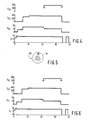
- FIG. 4 A typical prior art schedule for activating the cathodes and aging the tube for a 19V mini-neck colour picture tube having a quadripotential focus electron gun is illustrated graphically in Fig. 4.
- Heater filament and G1, G2 and G3 grid potentials are plotted versus time in minutes.
- the heater filaments are initially subjected to a relatively low potential (E F ) of about 6.5 volts for about 1 minute to preheat the cathodes, and then the heater voltage is raised to about 9.5 volts for about 1 minute to activate the cathodes. Aging begins immediately after activation.
- E F relatively low potential
- a voltage of about 8.5 volts is maintained on the cathode heater filaments throughout the 33 minute aging cycle.
- the G1 grid is subjected to a slightly lower potential of about 8 volts.
- the G1 grid potential is increased to about 15 volts, and the G2 grid is subjected to a substantially higher potential of about 300 volts.
- the G2 potential is increased to 350 volts, and 11 minutes after the EG1 is reduced to 10 volts.
- the G3 grid is subjected to a potential of about 350 volts for about 13 minutes.
- E F is maintained for about 1 minute after EG1, EG2 and EG3 have been turned off, and is subsequently reapplied for an additional two minutes to insure against the formation of detrimental deposits on the cathodes from the grids, and to further reduce any contaminants on the cathode surface.
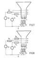
- FIG. 7 An arrangement for achieving the above activating and aging schedule is shown schematically in Fig. 7, wherein potential source E F supplies the cathode heater filaments, source EG1 supplies the grid G1 and source EG2 supplies both the G2 and G3 grids.
- the actual potential values for each gun element being aged are controlled by the values of the resistors.
- Typical values for resistors RK1-3 for example, are 150 ohms each, for RG1, 100 ohms, and for RG2, 5000 ohms. Since there is no resistor between G2 and G3, these grids are subjected to the same potential.
- the G3 grid when the G3 grid is subjected to a potential similar to that of G2, the positively charged carbon particles resulting from the dissociation of residual hydrocarbons are formed into a beam and directed back onto the cathodes, forming dark center cathodes similar to that illustrated in Fig. 5, wherein cathode 90 includes carbon deposit 92 in the center of emissive layer 94.
- the potential of the grid G3 In order to avoid such detrimental deposits, the potential of the grid G3 must be lowered to create a barrier to the positively charged particle beam.
- lowering the potential of the grid G3 too far can have at least two adverse effects. First, it reduces the effectiveness of gas dissociation, by reducing the energy of electron beam. Second, it reduces the effectiveness of G3 grid conditioning, by reducing the temperature produced by energy dissipation in the grid. Both residual gas and contaminants on the G3 grid can find their way to the cathodes during later tube operation, reducing emission and consequently shortening tube life.
- the G3 potential should be at least 100 volts, and at least 50 volts below the G2 potential, and preferably at least 150 volts and at least 100 volts below the G2 potential.
- EG2 was reduced to 400 volts, and a 5000 ohm resistor (RG3 in Fig. 8) was inserted into the circuit between the grids G2 and G3, resulting in potentials of 325 and 255 volts at the grids G2 and G3, respectively.
- the currents flowing to the grids G2 and G3 were 0.5 and 15 milliamps, respectively.
- Emission and emission slump are reported for each of the red, green and blue guns. Emission is reported in microamperes as an average ( ) of 10 to 12 samples, with standard deviations ( s ). Emission slump is reported as percent decrease in emission after 5 seconds at a filament potential of 5 volts and zero bias. Appearance of the cathodes after aging was visually rated as zero, light, moderate and heavy deposits, and reported without distinction between individual guns.
Landscapes
- Engineering & Computer Science (AREA)
- Manufacturing & Machinery (AREA)
- Manufacture Of Electron Tubes, Discharge Lamp Vessels, Lead-In Wires, And The Like (AREA)
Applications Claiming Priority (2)
| Application Number | Priority Date | Filing Date | Title |
|---|---|---|---|
| US87615086A | 1986-06-19 | 1986-06-19 | |
| US876150 | 1986-06-19 |
Publications (2)
| Publication Number | Publication Date |
|---|---|
| EP0250053A2 true EP0250053A2 (de) | 1987-12-23 |
| EP0250053A3 EP0250053A3 (de) | 1990-03-28 |
Family
ID=25367087
Family Applications (1)
| Application Number | Title | Priority Date | Filing Date |
|---|---|---|---|
| EP87201145A Ceased EP0250053A3 (de) | 1986-06-19 | 1987-06-16 | Verfahren zur Regeneration von Kathodenstrahlröhren |
Country Status (4)
| Country | Link |
|---|---|
| EP (1) | EP0250053A3 (de) |
| JP (1) | JPS6324530A (de) |
| KR (1) | KR880001015A (de) |
| CA (1) | CA1304774C (de) |
Family Cites Families (2)
| Publication number | Priority date | Publication date | Assignee | Title |
|---|---|---|---|---|
| US3966287A (en) * | 1975-06-27 | 1976-06-29 | Rca Corporation | Low-voltage aging of cathode-ray tubes |
| JPS61110935A (ja) * | 1984-11-05 | 1986-05-29 | Toshiba Corp | 陰極線管の製造方法 |
-
1987
- 1987-06-16 KR KR1019870006077A patent/KR880001015A/ko not_active Ceased
- 1987-06-16 EP EP87201145A patent/EP0250053A3/de not_active Ceased
- 1987-06-18 CA CA000540074A patent/CA1304774C/en not_active Expired - Lifetime
- 1987-06-19 JP JP62151524A patent/JPS6324530A/ja active Pending
Also Published As
| Publication number | Publication date |
|---|---|
| CA1304774C (en) | 1992-07-07 |
| EP0250053A3 (de) | 1990-03-28 |
| JPS6324530A (ja) | 1988-02-01 |
| KR880001015A (ko) | 1988-03-30 |
Similar Documents
| Publication | Publication Date | Title |
|---|---|---|
| US4395242A (en) | Method of electrically processing a CRT mount assembly to reduce afterglow | |
| US4515569A (en) | Method of electrically processing a CRT mount assembly to reduce arcing and afterglow | |
| US4457731A (en) | Cathode ray tube processing | |
| US3979632A (en) | Cathode ray tube having surface charge inhibiting means therein | |
| US4832646A (en) | Aging process for cathode ray tubes | |
| US4940440A (en) | Weak beam scanning of cathode ray tubes | |
| CA1304774C (en) | Aging process for cathode ray tubes | |
| US4503357A (en) | Cathode-ray tube | |
| US3589791A (en) | Processing of cathode-ray tubes | |
| CA1246242A (en) | High voltage processing of crt mounts | |
| US3321263A (en) | Cathode ray tube manufacture | |
| US4602186A (en) | Insulating mount for a CRT Einzel lens focus mask | |
| US5788549A (en) | Method of manufacturing color cathode ray tube | |
| US4687454A (en) | Method and device for heating the electrodes of an electron gun during its manufacture | |
| US7256536B2 (en) | Cathode ray tubes | |
| JPH0668811A (ja) | 陰極線管電子銃用抵抗器 | |
| JPH05283005A (ja) | 陰極線管の耐電圧処理方法 | |
| EP0635862B1 (de) | Kathodenstrahlröhre | |
| CN1040813C (zh) | 用于彩色显象管的一字型电子枪组件 | |
| US20020074925A1 (en) | Color picture tube free from deviation of convergence | |
| EP0333421A2 (de) | Kathodenstrahlröhre | |
| JPH04274138A (ja) | 陰極線管の製造方法 | |
| JPS63114024A (ja) | 陰極線管のシ−ズニング方法 | |
| JPH05258670A (ja) | 陰極線管の製造方法 | |
| JPH0320931A (ja) | 陰極線管のコンディショニング方法 |
Legal Events
| Date | Code | Title | Description |
|---|---|---|---|
| PUAI | Public reference made under article 153(3) epc to a published international application that has entered the european phase |
Free format text: ORIGINAL CODE: 0009012 |
|
| AK | Designated contracting states |
Kind code of ref document: A2 Designated state(s): DE ES FR GB NL |
|
| PUAL | Search report despatched |
Free format text: ORIGINAL CODE: 0009013 |
|
| AK | Designated contracting states |
Kind code of ref document: A3 Designated state(s): DE ES FR GB NL |
|
| RHK1 | Main classification (correction) |
Ipc: H01J 9/44 |
|
| 17P | Request for examination filed |
Effective date: 19900926 |
|
| RAP1 | Party data changed (applicant data changed or rights of an application transferred) |
Owner name: NORTH AMERICAN PHILIPS CORPORATION |
|
| RAP1 | Party data changed (applicant data changed or rights of an application transferred) |
Owner name: NORTH AMERICAN PHILIPS CORPORATION |
|
| 17Q | First examination report despatched |
Effective date: 19930706 |
|
| STAA | Information on the status of an ep patent application or granted ep patent |
Free format text: STATUS: THE APPLICATION HAS BEEN REFUSED |
|
| 18R | Application refused |
Effective date: 19931230 |
|
| RIN1 | Information on inventor provided before grant (corrected) |
Inventor name: REHKOPF, CHARLES HENRY Inventor name: REIGEL, FRANKLING GEORGE Inventor name: SIEFKER, DONALD LOUIS Inventor name: CHUNG, SAMUEL SUNWHEE Inventor name: STOWE, JAMES RICHARD |