EP0250039B1 - Methode zur Bestimmung der optimalen Höhe eines in niedriger Höhe über dem Meeresspiegel fliegenden Fahrzeuges - Google Patents
Methode zur Bestimmung der optimalen Höhe eines in niedriger Höhe über dem Meeresspiegel fliegenden Fahrzeuges Download PDFInfo
- Publication number
- EP0250039B1 EP0250039B1 EP87201112A EP87201112A EP0250039B1 EP 0250039 B1 EP0250039 B1 EP 0250039B1 EP 87201112 A EP87201112 A EP 87201112A EP 87201112 A EP87201112 A EP 87201112A EP 0250039 B1 EP0250039 B1 EP 0250039B1
- Authority
- EP
- European Patent Office
- Prior art keywords
- altitude
- vehicle
- signal
- optimal
- wave
- Prior art date
- Legal status (The legal status is an assumption and is not a legal conclusion. Google has not performed a legal analysis and makes no representation as to the accuracy of the status listed.)
- Expired - Lifetime
Links
- 238000000034 method Methods 0.000 title claims description 19
- 238000005259 measurement Methods 0.000 claims description 7
- 230000009897 systematic effect Effects 0.000 claims description 6
- 238000001228 spectrum Methods 0.000 description 5
- 230000001419 dependent effect Effects 0.000 description 3
- 238000004364 calculation method Methods 0.000 description 2
- 230000000694 effects Effects 0.000 description 2
- 238000002474 experimental method Methods 0.000 description 2
- 238000004088 simulation Methods 0.000 description 2
- 238000001514 detection method Methods 0.000 description 1
- 238000010586 diagram Methods 0.000 description 1
Images


Classifications
-
- G—PHYSICS
- G05—CONTROLLING; REGULATING
- G05D—SYSTEMS FOR CONTROLLING OR REGULATING NON-ELECTRIC VARIABLES
- G05D1/00—Control of position, course, altitude or attitude of land, water, air or space vehicles, e.g. using automatic pilots
- G05D1/04—Control of altitude or depth
- G05D1/042—Control of altitude or depth specially adapted for aircraft
Definitions
- the present invention relates to a method for the determination The altitude of the optimal altitude for control of the altitude of a vehicle, flying at a low altitude over a sea surface, like an anti-ship missile.
- the objectmissile which method comprises the determination of the distance between the sea surface and the vehicle by an altimeter, placed in the vehicle, which altimeter gives an altitude signal, which varies depending on the wave movements of the sea surface, which method comprises the processing of the altitude signal in a signal processing unit, which gives an altitude control signal to the steering means of the vehicle, depending on the difference between the actual altitude and the optimal altitude.
- the invention also relates to a device for carrying out the method.
- an anti-ship missile In order to avoid detection by radar or other reconnaissance equipment, and in order to, if possible, hit a marine target directly, an anti-ship missile should fly towards the target at the lowest possible altitude, but with a safe margin to the crests of the waves. For high sea-states, the missile must be commanded to a considerably higher path than for calm sea. As the sea-state often varies locally along a missile trajectory, it is desirable to control the altitude of the missile according to the local sea-state. The optimal altitude for the missile has to be determined according to the local sea-state. For this purpose it is necessary to provide the missile with an altimeter, which measures the vertical distance between the vehicle and the sea surface along the trajectory of the missile towards the target.
- a method for the control of the altitude of a vehicle flying towards a marine target comprises the determination of the distance between the vehicle and the sea surface by an altimeter, carried by the vehicle. Every determined minimal value of this distance, which thus corresponds to a wave crest, is stored in a sample-and-hold circuit during a certain period of time, which corresponds approximately to a wave period. The stored minimal value is compared, in a command circuit, with a reference altitude. If the stored minimal value should not coincide with the reference altitude, the command circuit will give such an altitude control signal to the steering means of the vehicle, that the flight path of the vehicle will be placed on an altitude above the wave top in question, corresponding to the reference altitude.
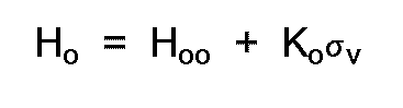
- the optimal altitude consists, according to DE Auslegeschrift 24 36 791, of the reference altitude plus the height of the wave top, that is to say the wave amplitude.
- the optimal altitude in this case consists of a constant term and a variable term, which is equal to the wave top height.
- the last term thus forms the part by which the optimal altitude can be varied as a function of the sea state. This term, however, only makes possible rather slight variations, which means, that the reference altitude must be chosen unnecessarily high at low sea-states in order to maintain a low risk for a wave hit at high sea-states.
- the object of the present invention is to provide a method and a corresponding device for the determination of the optimal altitude, in which the information on the wave movement obtained by a measurement of the distance between the vehicle and the sea surface, combined with knowledge of the statistics of the wave movements, is utilized efficiently in order to determine a term, which is dependent on the locally prevailing sea state, and which corresponds substantially to the variable term, mentioned above, which makes it possible to change the optimal altitude considerably, when needed, and which thus admits, that a term, corresponding substantially to said constant term, is given a rather low value, without increasing the risk of a wave hit.
- the altitude signal is filtered in the signal processing unit to eliminate any superimposed signals, the frequencies of which are outside a predetermined range of frequencies, comprising the range of frequencies of the wave movement, that the rms-value, that is to say the standard deviation or a value related to this of the filtered altitude signal like the mean amplitude, is determined in the signal processing unit, that an acceptable risk P o for a wave hit of the vehicle is established, and that the optimal altitude is calculated from the rms-value determined and from the established risk for a wave hit for the vehicle.
- the optimal altitude is advantageously calculated considering the systematic errror of measurement of the altimeter and the variation of altitude of the vehicle around the reference altitude.
- the systematic error of measurement of the altimeter and the variation of altitude of the vehicle are normally distributed with the mean value zero and the standard deviations ⁇ F and ⁇ h , in which case the optimal altitude H o is calculated from the relationship where ⁇ v is the standard deviation of the sea-surface deviation due to the wave movement, L o is the flight range of the vehicle and ⁇ o is the characteristic wave length of the wave movement.
- said predetermined range of frequencies is preferably chosen such, that the filtered altitude signal corresponds to the sum of the wave movement and the variation of the altitude of the vehicle around the reference altitude, whereby its rms-value corresponds to
- Figure 1 shows an anti-ship missile, flying at a low altitude over a sea surface.
- Figure 2 is a block diagram showing an altimeter, a signal processing unit and the steering means for the missile.
- Figure 3 shows the signal spectrum of the altitude signal.
- an anti-ship missile 1 is shown, flying at a low altitude over a rough sea surface.
- the wave height H v (fig. 1) whereby here is meant the vertical distance between the wave top and the wave through, can be regarded as Rayleigh-distributed
- the so-called wave spectrum determines how rapidly the momentary wave height varies along a flight path.
- Several models for the determination of the dependence of the wave spectrum on wind force, the duration of the wind etc. have been proposed.
- the Neuman-Pierson model can be mentioned, described in G. Neuman, Pierson, "A comparison of various theoretical wave spectra, Proceedings of a symposium of the behaviour of ships in a seawave", Vol.
- an altimeter 2 (fig. 2), which is for instance a radar altimeter.
- the altimeter 2 continuously measures the distance between the missile 1 and the sea surface and gives an altitude signal H(t) corresponding to this distance to a signal processing unit 3, which in the example shown (fig. 1) is placed in the missile, but which can also be placed in a fixed site.
- the signal processing unit 3 receives the altitude signal H(t) and converts it to give to the steering means 4 of the missile 1 an altitude control signal R, which is dependent on the difference between the actual altitude of the missile 1 and the optimal altitude H o (in the example shown in fig. 1 there is no difference, but the actual altitude is equal to the optimal altitude).
- FIG 3 the signal spectrum of the altitude signal H(t) is shown.
- the components of the altitude signal H(t) lie in different frequency ranges.
- H o and F have the frequency zero, h(t) is concentrated to the frequency range 0 ⁇ f ⁇ f1 in fig. 3.
- v(t) lies in the frequency range f1 ⁇ f ⁇ f2 in fig. 3, whilst n(t) substantially has frequencies, which are larger than f2.
- f1 is of the order of magnitude of 1 Hz or less and f2 is about 5 - 20 Hz depending on the sea state.
- the signal processing unit 3 comprises a high-pass filter 5, a low pass filter 6, means 7 for the determination of rms-value (root mean square value) and a calculation means 8 for calculation and emitting of said control signal R.
- the altitude signal H(t) is allowed to pass the high-pass filter 5, which has the pass-band f > f1 and thus suppresses the components H o , F and h(t) but lets the wave movement component v(t) and the noise component n(t) pass.
- the filtered signal H1(t), which is the output of the high-pass filter 5, is allowed to pass the low-pass filter 6, which has the pass-band f ⁇ f2 and thus suppresses thehigh-frequency noise component n(t) but lets the wave movement component v(t) pass.
- the wave movement component v(t) thus forms the only remaining component of the altitude signal H(t) in the filtered signal output H2(t) from by the low-pass filter 6.
- the filtered signal H2(t) is connected to a rectifier 9, which forms part of the means 7.
- the rectified output signal H3(t) is connected to a low-pass filter 10, which also forms part of the means 7.
- the signal H4(t), emitted from the low pass filter 10, is directly proportional to the rms-value of the wave movement and thus also to its standard deviation v .
- H4(t) k o ⁇ v .
- k o ⁇ 2/ ⁇ if the rectifier 9 is a full-wave rectifier
- k o 1/2 ⁇ 2/ ⁇ , if the rectifier 9 is a half-wave rectifier.
- the signal H4(t) is connected to an amplifier 11, which also forms part of the means 7, and which has the gain 1/k o and thus emits a signal H5(t), which is equal to the standard deviation v for the momentary value of the wave movement.
- the signal H5(t) is received by the means 8, which calculates the optimal altitude H o in a way to be described more in detail below.
- the means 8 also receives the signal H(t) from the altimeter 2 and therefrom it determines the actual altitude of the missile 1. The means 8 then compares the actual altitude with the optimal altitude H o and emits an altitude control signal R, depending on the difference between them, to the steering means 4 of the missile 1.
- an acceptable risk P o is established for a wave hit by the missile 1. If the systematic error of measurement F of the altimeter 2 and the variation of altitude h(t) of the missile 1 around the reference altitude is presumed to be normally distributed with the mean value 0 and the standard deviation ⁇ F and ⁇ h , the risk or probability P o that the missile should hit the waves during a flight range L o can be given by the following approximate relationship, provided that H v is Rayleigh-distributed according to the formula, which has been given earlier.
- ⁇ o is the characteristic wave length of the waves, which can be determined from the altitude signal H(t), for instance by counting the number N o of zero-crossings for the filtered signal H2(t) during a certain period of time T, whereupon ⁇ o is calculated from where V o is the speed of flight for the missile 1.
- empiric relationships between ⁇ v and ⁇ o can be utilized for an estimation of ⁇ o for instance according to Pierson-Moskowitz model, which has been mentioned earlier.
- the limit frequency of the high-pass filter 5 is given a value, that is so much less than f1, that the high-pass filter will, like before, suppress the components H o and F of the altitude signal H(t), but will let through the components v(t) and n(t) and also the component of altitude variation h(t).
- H5(t) H5(t)
- ⁇ F can be determined by simulations or experiments.
- H5(t) ⁇ v 2
- H5(t) ⁇ v 2 + ⁇ h 2
Landscapes
- Engineering & Computer Science (AREA)
- Aviation & Aerospace Engineering (AREA)
- Radar, Positioning & Navigation (AREA)
- Remote Sensing (AREA)
- Physics & Mathematics (AREA)
- General Physics & Mathematics (AREA)
- Automation & Control Theory (AREA)
- Radar Systems Or Details Thereof (AREA)
- Control Of Position, Course, Altitude, Or Attitude Of Moving Bodies (AREA)
- Table Devices Or Equipment (AREA)
- Length Measuring Devices With Unspecified Measuring Means (AREA)
Claims (9)
- Verfahren zur Bestimmung der optimalen Höhe für die Höhensteuerung eines Fahrzeugs (1), welches in geringer Höhe über die Wasseroberfläche fliegt, beispielsweise einer Anti-Schiffsrakete, wobei das Verfahren die Bestimmung der Entfernung zwischen der Wasseroberfläche und dem Fahrzeug mittels eines im Fahrzeug angeordneten Entfernungsmeßgerätes (2) umfaßt, welches ein Höhensignal (H(t)) entsprechend der Entfernung liefert, wobei das Signal sich in Abhängigkeit von der Wellenbewegungen der Wasseroberfläche verändert, und die Bearbeitung des Höhensignals in einer Signalbearbeitungseinrichtung (3), die ein Höhensteuerungssignal (R) zur Steuerungseinrichtung des Fahrzeugs (4) liefert, das von der Differenz zwischen momentaner Höhe und der optimalen Höhe Ho abhängt, dadurch gekennzeichnet, daß das Höhensignal (H(t)) in der Signalbearbeitungseinrichtung (3) gefiltert wird, um alle überlagerten Signale auszuschalten, deren Frequenzen außerhalb eines vorbestimmten Frequenzbereiches liegen, der den Frequenzbereich der Wellenstruktur umfaßt, daß der rms-Wert, d.h. die Standartabweichung oder ein auf diese bezogener Wert des gefilterten Höhensignals H₂(t) entsprechend der Hauptamplitude durch die Signalbearbeitungseinrichtung (3) bestimmt wird, daß ein annehmbares Risiko Po bezüglich einer Wellenberührung des Fahrzeugs (1) festgelegt wird und daß die optimale Höhe Ho aus dem bestimmten rms-Wert oder einem darauf bezogenen Wert und aus dem festgesetzten Risiko Po einer Wellenberührung des Fahrzeugs (1) berechnet wird.
- Verfahren nach Anspruch 1, dadurch gekennzeichnet, daß die optimale Höhe Ho unter Berücksichtigung des systematischen Meßfehlers des Höhenmessers (2) und der Variation der Höhe um die Referenzhöhe des Fahrzeugs (1) berechnet wird.
- Verfahren nach Anspruch 2, dadurch gekennzeichnet, daß angenommen wird, daß der systematische Meßfehler des Höhenmessers und die Variationen des Fahrzeugs normalverteilt mit dem Hauptwert Null und der Standartabweichung σF und σh ist, und daß die optimale Höhe Ho aus der Beziehung

- Vorrichtung nach Anspruch 3, dadurch gekennzeichnet, daß angenommen wird, daß die Höhenvariation des Fahrzeugs (1) um die befohlene Höhe unabhängig von äußeren Umständen (Einflüssen) ist und daß der vorbestimmte Bereich der Frequenzen derart ausgewählt wurde, daß die Höhenvariationen des Fahrzeugs um die Referenzhöhe ausgeschlossen wird, wenn das Höhensignal (H(t)) gefiltert wurde, wobei das gefilterte Höhensignal (H₂(t)) der Wellenbewegung und sein rms-Wert der Standartabweichung σv des momentanen Wertes der Wellenbewegung entsprechen, und daß die optimale Höhe aus der Beziehung

- Verfahren nach Anspruch 4, dadurch gekennzeichnet, daß die optimale Höhe Ho aus der näherungsweisen Beziehung
berechnet wird. - Verfahren nach Anspruch 3, dadurch gekennzeichnet, daß der vorbestimmte Bereich der Frequenzen derart ausgewählt wurde, daß das gefilterte Höhensignal (H₂(t)) der Summe aus der Wellenbewegung und der Variation der Höhe des Fahrzeugs um die Referenzhöhe entspricht, wobei sein rms-Wert

- Verfahren nach Anspruch 6, dadurch gekennzeichnet, daß die optimale Höhe Ho aus der näherungsweisen Beziehung

- Verfahren nach Anspruch 6, dadurch gekennzeichnet, daß die optimale Höhe Ho aus der näherungsweisen Beziehung

- Vorrichtung zur Höhensteuerung einer optimalen Höhe für ein fliegendes Fahrzeug (1), beispielsweise eine Anti-Schiffsrakete, die in relativ niedriger Höhe über eine Wasseroberfläche fliegt, umfassend einen im Fahrzeug angeordneten Höhenmesser, der zur Messung des Abstands zwischen der Wasseroberfläche und dem Fahrzeug dient und ein Höhensignal (H(t)) erzeugt, das diesem Abstand entspricht, wobei das Signal in Abhängigkeit des Wellenaufbaus der Wasseroberfläche variiert, und eine Signalbearbeitungseinrichtung (3) zum Empfang des Höhensignals (H(t)) und zur Abgabe eines Höhensteuerungssignals auf die Steuerungseinrichtung (4) des Fahrzeugs in Abhängigkeit von der Differenz zwischen der Höhe des Fahrzeugs und der optimalen Höhe Ho, dadurch gekennzeichnet, daß die Signalbearbeitungseinrichtung (3), dazu dient,- das Höhensignal (H(t)) zu filtern, um alle überlagerten Signale auszuschließen, deren Frequenzen außerhalb eines vorbestimmten Bereiches liegen, der den Bereich der Frequenzen der Wellenbewegung umfaßt.- den rms-Wert des gefilterten Höhensignals (H(t)) zu bestimmen,- die optimale Höhe Ho unter Berücksichtigung des bestimmten rms-Wertes und eines festgelegten, annehmbaren Risikos Po einer Wellenberührung des Fahrzeugs (1) zu berechnen.
Applications Claiming Priority (2)
| Application Number | Priority Date | Filing Date | Title |
|---|---|---|---|
| SE8602728 | 1986-06-19 | ||
| SE8602728A SE453615B (sv) | 1986-06-19 | 1986-06-19 | Sett och anordning for att bestemma optimal flyghojd for en over en sjoyta lagt flygande farkost |
Publications (3)
| Publication Number | Publication Date |
|---|---|
| EP0250039A2 EP0250039A2 (de) | 1987-12-23 |
| EP0250039A3 EP0250039A3 (en) | 1989-10-18 |
| EP0250039B1 true EP0250039B1 (de) | 1993-02-10 |
Family
ID=20364856
Family Applications (1)
| Application Number | Title | Priority Date | Filing Date |
|---|---|---|---|
| EP87201112A Expired - Lifetime EP0250039B1 (de) | 1986-06-19 | 1987-06-12 | Methode zur Bestimmung der optimalen Höhe eines in niedriger Höhe über dem Meeresspiegel fliegenden Fahrzeuges |
Country Status (6)
| Country | Link |
|---|---|
| EP (1) | EP0250039B1 (de) |
| DE (1) | DE3784103T2 (de) |
| DK (1) | DK168254B1 (de) |
| FI (1) | FI89839C (de) |
| NO (1) | NO172208C (de) |
| SE (1) | SE453615B (de) |
Families Citing this family (1)
| Publication number | Priority date | Publication date | Assignee | Title |
|---|---|---|---|---|
| ITMI910497A1 (it) * | 1990-03-05 | 1991-09-06 | Aerospatiale Soc Nat Indu Strielle | Dispositivo per la guida automatica di un aeromobile a raso mare. |
Family Cites Families (3)
| Publication number | Priority date | Publication date | Assignee | Title |
|---|---|---|---|---|
| DE2436791C3 (de) * | 1974-07-31 | 1978-09-14 | Messerschmitt-Boelkow-Blohm Gmbh, 8000 Muenchen | Höhenregelkreis für einen Flugkörper, der Schiffsziele auf einer vorgegebenen Referenzhöhe über See anfliegt |
| DE2511233C2 (de) * | 1975-03-14 | 1977-03-10 | Dornier Gmbh | Verfahren zur Verhinderung ungewollter Land- oder Wasserberührung von in niedriger Höhe fliegenden Fluggeräten |
| GB2043388B (en) * | 1979-02-09 | 1983-08-17 | Boeing Co | Minimum safe altitude monitoring indicating and warning system |
-
1986
- 1986-06-19 SE SE8602728A patent/SE453615B/sv not_active IP Right Cessation
-
1987
- 1987-06-12 DE DE8787201112T patent/DE3784103T2/de not_active Expired - Fee Related
- 1987-06-12 EP EP87201112A patent/EP0250039B1/de not_active Expired - Lifetime
- 1987-06-16 NO NO872519A patent/NO172208C/no unknown
- 1987-06-16 FI FI872669A patent/FI89839C/fi not_active IP Right Cessation
- 1987-06-18 DK DK310287A patent/DK168254B1/da not_active IP Right Cessation
Also Published As
| Publication number | Publication date |
|---|---|
| DK168254B1 (da) | 1994-02-28 |
| FI872669A0 (fi) | 1987-06-16 |
| NO872519L (no) | 1987-12-21 |
| NO172208B (no) | 1993-03-08 |
| NO872519D0 (no) | 1987-06-16 |
| DK310287A (da) | 1987-12-20 |
| SE8602728L (sv) | 1987-12-20 |
| EP0250039A3 (en) | 1989-10-18 |
| EP0250039A2 (de) | 1987-12-23 |
| NO172208C (no) | 1993-06-16 |
| FI89839C (fi) | 1993-11-25 |
| DK310287D0 (da) | 1987-06-18 |
| SE8602728D0 (sv) | 1986-06-19 |
| DE3784103D1 (de) | 1993-03-25 |
| SE453615B (sv) | 1988-02-15 |
| FI872669A7 (fi) | 1987-12-20 |
| FI89839B (fi) | 1993-08-13 |
| DE3784103T2 (de) | 1993-06-03 |
Similar Documents
| Publication | Publication Date | Title |
|---|---|---|
| Yumori | Real time prediction of ship response to ocean waves using time series analysis | |
| US4725811A (en) | Wind shear detection and alerting system | |
| US4589070A (en) | Airborne wind shear response system | |
| Khan | Ocean-clutter model for high-frequency radar | |
| EP0743582B1 (de) | Verfahren und Gerät zur linearen Echtzeitschätzung eines Flugzeugmassenmittelpunktes | |
| EP0235963B1 (de) | Erkennung der vertikalen Windscherung für ein Flugzeug | |
| JPS5810684B2 (ja) | 警報装置 | |
| US4951047A (en) | Negative climb after take-off warning system | |
| US20240004060A1 (en) | Automatic obstacle avoidance method, electronic device, and unmanned aerial vehicle | |
| EP0250039B1 (de) | Methode zur Bestimmung der optimalen Höhe eines in niedriger Höhe über dem Meeresspiegel fliegenden Fahrzeuges | |
| EP0560744A1 (de) | Verfahren zur Radarzielverfolgung | |
| EP4300136B1 (de) | Verfahren zur automatischen hindernisvermeidung, elektronische vorrichtung und unbemanntes luftfahrzeug | |
| CN111936741A (zh) | 用于控制涡轮的控制系统、用于控制涡轮的方法和风力涡轮 | |
| US4940988A (en) | Two parameter clutter map | |
| CA1241082A (en) | Warning system for tactical aircraft | |
| US5109230A (en) | Method for aircraft velocity error detection with a Doppler radar | |
| NO169921B (no) | Anordning til paavisning av fartoeyer | |
| US4916447A (en) | Warning system for aircraft landing with landing gear up | |
| US4868916A (en) | Excessive ground-closure rate alarm system for aircraft | |
| US8508387B2 (en) | Systems and methods for aircraft windshear detection | |
| US5493293A (en) | Method and apparatus for reducing false wind shear alerts | |
| JP2961132B1 (ja) | 航走体放射雑音からのドップラ周波数検出による航走体速度検出装置及びその方法 | |
| RU2070729C1 (ru) | Система стабилизации продольного движения судна на подводных крыльях | |
| JP3086072B2 (ja) | 電波高度計 | |
| JPH0367594B2 (de) |
Legal Events
| Date | Code | Title | Description |
|---|---|---|---|
| PUAI | Public reference made under article 153(3) epc to a published international application that has entered the european phase |
Free format text: ORIGINAL CODE: 0009012 |
|
| AK | Designated contracting states |
Kind code of ref document: A2 Designated state(s): DE FR GB IT |
|
| PUAL | Search report despatched |
Free format text: ORIGINAL CODE: 0009013 |
|
| AK | Designated contracting states |
Kind code of ref document: A3 Designated state(s): DE FR GB IT |
|
| 17P | Request for examination filed |
Effective date: 19890906 |
|
| 17Q | First examination report despatched |
Effective date: 19910529 |
|
| ITF | It: translation for a ep patent filed | ||
| GRAA | (expected) grant |
Free format text: ORIGINAL CODE: 0009210 |
|
| AK | Designated contracting states |
Kind code of ref document: B1 Designated state(s): DE FR GB IT |
|
| ET | Fr: translation filed | ||
| REF | Corresponds to: |
Ref document number: 3784103 Country of ref document: DE Date of ref document: 19930325 |
|
| PLBE | No opposition filed within time limit |
Free format text: ORIGINAL CODE: 0009261 |
|
| STAA | Information on the status of an ep patent application or granted ep patent |
Free format text: STATUS: NO OPPOSITION FILED WITHIN TIME LIMIT |
|
| 26N | No opposition filed | ||
| REG | Reference to a national code |
Ref country code: GB Ref legal event code: IF02 |
|
| PGFP | Annual fee paid to national office [announced via postgrant information from national office to epo] |
Ref country code: GB Payment date: 20050608 Year of fee payment: 19 Ref country code: FR Payment date: 20050608 Year of fee payment: 19 |
|
| PGFP | Annual fee paid to national office [announced via postgrant information from national office to epo] |
Ref country code: DE Payment date: 20050609 Year of fee payment: 19 |
|
| PG25 | Lapsed in a contracting state [announced via postgrant information from national office to epo] |
Ref country code: GB Free format text: LAPSE BECAUSE OF NON-PAYMENT OF DUE FEES Effective date: 20060612 |
|
| PGFP | Annual fee paid to national office [announced via postgrant information from national office to epo] |
Ref country code: IT Payment date: 20060630 Year of fee payment: 20 |
|
| PG25 | Lapsed in a contracting state [announced via postgrant information from national office to epo] |
Ref country code: DE Free format text: LAPSE BECAUSE OF NON-PAYMENT OF DUE FEES Effective date: 20070103 |
|
| GBPC | Gb: european patent ceased through non-payment of renewal fee |
Effective date: 20060612 |
|
| REG | Reference to a national code |
Ref country code: FR Ref legal event code: ST Effective date: 20070228 |
|
| PG25 | Lapsed in a contracting state [announced via postgrant information from national office to epo] |
Ref country code: FR Free format text: LAPSE BECAUSE OF NON-PAYMENT OF DUE FEES Effective date: 20060630 |