EP0250022A2 - Tragbarer hypodermatischer Injektor - Google Patents
Tragbarer hypodermatischer Injektor Download PDFInfo
- Publication number
- EP0250022A2 EP0250022A2 EP87201015A EP87201015A EP0250022A2 EP 0250022 A2 EP0250022 A2 EP 0250022A2 EP 87201015 A EP87201015 A EP 87201015A EP 87201015 A EP87201015 A EP 87201015A EP 0250022 A2 EP0250022 A2 EP 0250022A2
- Authority
- EP
- European Patent Office
- Prior art keywords
- injector
- assembly
- containment
- hereinbefore
- reader
- Prior art date
- Legal status (The legal status is an assumption and is not a legal conclusion. Google has not performed a legal analysis and makes no representation as to the accuracy of the status listed.)
- Withdrawn
Links
Images


Classifications
-
- A—HUMAN NECESSITIES
- A61—MEDICAL OR VETERINARY SCIENCE; HYGIENE
- A61M—DEVICES FOR INTRODUCING MEDIA INTO, OR ONTO, THE BODY; DEVICES FOR TRANSDUCING BODY MEDIA OR FOR TAKING MEDIA FROM THE BODY; DEVICES FOR PRODUCING OR ENDING SLEEP OR STUPOR
- A61M5/00—Devices for bringing media into the body in a subcutaneous, intra-vascular or intramuscular way; Accessories therefor, e.g. filling or cleaning devices, arm-rests
- A61M5/178—Syringes
- A61M5/30—Syringes for injection by jet action, without needle, e.g. for use with replaceable ampoules or carpules
Definitions
- This invention concerns an endermic injector of a type loaded by hand and with a storage of ejection force by means of spring elements.
- the injector according to the invention serves to inject pharmaceutical substances, such as insulin, without using a needle.
- Patent US 2,717,597 discloses an injector apparatus having a very complicated structure. This injector comprises in the area of its head a chamber to hold a special phial containing the medicament.
- This apparatus entails noteworthy difficulties when being loaded since it cannot be loaded from outside but has to be partly dismantled for the introduction of the special phial.
- the apparatus comprises an inadequate safety system and is not fully hygienic as it is difficult to clean; besides, the medicament cannot be drawn from normal, commercially available phials.
- the does to be injected is unchangeable or else, if the dose is to be varied, it is necessary to employ phials of different capacities.
- Patent US 2,737,946 too discloses an injector having a very complicated structure.
- the medicament is held in a special phial, which is inserted near the head of the injector when it is to be used.
- the phial is complex and hard to embody and entails problems of safety, cleanliness and a proper seal.
- This patent like the previous one, does not permit the medicament to be loaded from the outside with normal, commercially available phials nor every required dose to be injected.
- the pressure which forces the medicament through the small outlet hole is provided by a gas which has been compressed beforehand during loading and which is kept momentarily in a chamber within the injector itself.
- Patent US 2,928,390 discloses an injector which enables the medicament to be loaded and measured from without and drawn from normal, commercially available phials.
- the injector works in two stages; the first and faster stage enables the medicament to overcome the compactness of the skin, while the second and slower stage permits an excellent penetration of the medicament.
- the injector has an exceptionally complex structure, which makes it heavy, hard to handle and too expensive; moreover, its sterilisation and maintenance cause great problems.
- compressed air is employed to load the springs providing the thrust for the cylinders which generate the outgoing pressure of the medicament, and this entails a considerable drawback since the injections can only be performed when an independent unit to provide compressed air is available; furthermore, a person suffering from diabetes certainly cannot carry such a device with him.
- Patent US 3,330,276 discloses a device which can measure and load the medicament from without and can draw it from normal, commercially available phials, but which has a very heavy and complex structure, is difficult to handle and has a very complicated system for installing and positioning the phial, thus involving great difficulties in using and carrying the device.
- the phial is not properly protected and is prone to breakage, thus restricting the ability to carry the device. Moreover, only one type of medicament can be loaded into this device at a time; this fact restricts its use since some patients, such as diabetics, require injections consisting of components drawn from different phials and advantageously mixed before being injected.
- a great shortcoming of this device is the inclusion of an air filter fitted near the phial holder, this filter being needed to maintain the desired pressure within the phial itself during loading of the medicament and also to maintain sterile conditions within the phial.
- a further drawback is the fact that the phial can explode during ejection if the valve is left in the drawing position accidentally. Moreover, the device has to be fully unloaded after ejection before it can be re-loaded.
- Patent US 3,330,277 discloses a variant of US 3,330,276, but this variant does not apply any substantial functional changes or improvements as regards the shortcomings of US 3,330,276.
- Patent US 3,526,225 discloses an injector to be used in conjunction with an outside source of compressed air. This invention is therefore suitable only for use in a surgery for multiple vaccinations and does not provide for mixture of medicaments.
- Patent US 3,714,943 concerns a device which can lodge within itself a plurality of special phials the contents of which can be injected one by one. In this case too it is not possible to load the medicament from outside and to use normal, commercially available phials.
- the pressure needed to eject the medicament is generated by a gas compressed beforehand in a chamber inside the device itself. As we said earlier, this entails problems of a proper seal.
- US 3,827,601 discloses a device operated by hand and of no greater power, this device not being relevant for the purposes of our invention.
- US 3,908,651 discloses an injector which enables the measurement and loading of the medicament to be performed outside, the medicament being drawn from normal, commercially available phials.
- This injector comprises an injection head of a complex structure together with a safety device which prevents the medicament flowing back into the phial in the event of wrong operation.
- the injector includes also a very complicated fixture system and is suitable to administer the medicament from only one phial at a time, and this is a great drawback, as we said earlier. Moreover, the patent does no disclose how the injecting action is achieved, graduated and developed.
- EP 0114792 discloses an endermic injector suitable to draw from two external phials the material to be injected. It comprises a particularly complex system to modify and clean the injecting assembly. Moreover, it has a considerable bulk and is therefore not suitable for personal use and for being carried by its user.
- the present invention tends to overcome the shortcomings of the prior art by providing many benefits and advantages.
- a further purpose of the invention is to provide an endermic injector which is light and easy to use and needs little maintenance.
- Another purpose of the invention is to provide an injector with a containment assembly which is simple and easy to replace, dismantle and sterilise.
- Yet another purpose is to provide a device which can be set and regulated easily, even by unskilled persons, so as to adapt the injecting action to the various requirements of the user's skin.
- a further purpose is to provide a device in which it is easy to check the quantity loaded.
- the invention also has the purpose of facilitating the ejection actuation without transmitting vibrations or jerks to the apparatus.
- the present invention tends to overcome all the drawbacks of the known art by offering an endermic injector which is light, easy to handle, regulate and sterilise, easy to actuate and which provides easy reading of the value of medicament loaded.
- the container for the liquid to be injected forms part of a containment assembly which cooperates with a phial container of a removable type that does not form part of this invention.
- the containment assembly comprises means which are secured momentarily to the phial container and enable the required doses to be loaded.
- the containment assembly is so formed that it can be fully replaced in order to enable it to be prepared quickly and to be dismantled completely and sterilised without any need for haste.
- the assembly to aspirate and to store energy is provided with a double regulation capability so as to cover a very wide range of requirements of the human skin, for every skin possesses different characteristics and requirements and the pressure of an injection must therefore be adapted to the individual in question.
- two adjustments can be made, a first rough adjustment and a second fine adjustment suited to the specific skin requirements.
- the aspiration assembly comprises means to show the quantity loaded (by aspiration), the means being easy to read and thus preventing mistakes or confusion.
- means are provided to prevent accidental actuation of the injection, thus obviating undesired ejections with loss of medical sustances.
- actuation means are included which are suitable to avoid creation of vibrations in the injector.
- these actuation means can be operated axially so that any vibrations or movements caused by actuation are transmitted axially.
- the invention is therefore embodiment with a portable endermic injector of a mechanical type which comprises an aspiration and containment chamber, an assembly to aspirate and to store, a cocking and trigger assembly and an assembly to read the quantity aspirated and is characterized in that: - a containment assembly comprising the aspiration and containment chamber and a piston is screwed onto a frontal container, - the assembly to aspirate and to store energy comprises means to regulate the pre-loading of a spring assembly which consist of spacer rings and means having variable axial reciprocal positions, and - the reader assembly comprises a threaded tract and a slider cooperating with a graduated area.
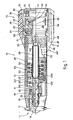
- Fig.1 shows an injector device which comprises a containment assembly 11, an assembly 12 to aspirate and to store energy, a trigger assembly 13 and a reader assembly 14.
- the containment assembly 11 is screwed onto a frontal container 15 owing to an injection head 16.
- the injection head 16 comprises rods 17 which assist the screwing and unscrewing of the containment assembly 11 and make possible the anchorage of an external assembly which mixes and delivers liquid to be aspirated.
- the containment assembly 11 consists not only of the injection head 16 but also of a piston 19, which slides in an aspiration and containment chamber, and of a rear containment cap 18, abutment ring 20 and packing 21.
- Every part of the containment assembly 11 can be dismantled, and the assembly can be easily and quickly steril ised.
- the containment assembly 11 can be easily replaced with an identical assembly or with another having a greater or smaller loading capacity and therefore a different capability.
- connection of the piston 19 to a shaft 29 is of a known type and provides a quick and easy axial connection.
- the aspiration and storage assembly 12 comprises the shaft 29 bearing an abutment ring 26.
- the shaft 29 and ring 26 can only move axially owing to the inclusion of a guide pin 27 which runs in an appropriate lengthwise groove inside a containment and guide sleeve 23.
- Springs 28 thrust against the abutment ring 26 and also press against a perforated cap 30. If it is desired to enhance the action of the springs 28, their pre-loading is altered by placing spacer rings 226 of various thicknesses between the springs 28 and the abutment ring 26. These spacer rings 226 provide a rough adjustment and can also be placed between the springs 28 and the perforated cap 30.
- the abutment ring 26 abuts against an inner face 115 of the frontal container 15.
- a resilient ring 126 serves for damping and silencing purposes.
- the frontal container 15 can be screwed onto, or unscrewed from, the containment and guide sleeve 23; the figure shows them screwed together.
- the reciprocal desired positions of the containment sleeve 23 and container 15 are secured by a dowel 22 which cooperates with one or more lengthwise grooves in the containment and guide sleeve 23.
- Fine adjustment of the pre-loading of the springs 28 and therefore of the power of injection is obtained by altering the reciprocal positions of the sleeve 23 and container 15.
- the frontal container 15 is screwed onto the containment and guide sleeve 23 and is partially surrounded by a reader sleeve 24 (Fig.2).
- the desired fine adjustment is obtained by screwing the container 15 on the containment sleeve 23 to a greater or lesser extent.
- Grooves 55 located along a circumference in an auxiliary sleeve 124 solidly fixed to the reader sleeve 24 are provided for the positioning of the frontal container 15 in relation to the containment sleeve 23.
- the push button 52 is secured with an engagement tooth 51; if the push button 52 is operated, the protrusion 54 is freed from the groove 55 in question and the frontal container 15 can be rotated in relation to the containment sleeve 23.
- the containment sleeve 23 and reader sleeve 24 are solidly fixed together with a dowel 25.
- Suitable marks on the container 15 cooperate with the front edge of the auxiliary sleeve 124 and show the value of the adjustment.
- the loading and ejection system or cocking and trigger assembly 13 is known and is described in EP 0114792.
- This system which cooperates with a threaded portion 146 on the shaft 29, comprises an annular container 37 fixed solidly to a hand grip 32 by a dowel 36.
- the annular container 37 includes radial hollows within which there can slide teeth 39 kept in the cocked position by an actuator 40.
- the actuator 40 is pressed against an annular lever 41 by spring means 43; and annular lever is normally rested on a rear abutment ring 42 which cooperates with a stopper 44.
- the annular lever 41 is connected to a push button 38 by a pin 45. If the push button 39 is operated, the lever 41 is displaced and pushes the actuator 40 forwards.
- the actuator 40 Being pushed forward, the actuator 40 frees the teeth 39, which become partially located within the actuator 40 and free the shaft 29, which is thrust forward by the springs 28.
- the inclined surface on the teeth 39 has the result that, with the actuator 40 moved back once more, the teeth 39 are re-positioned in the cocking position of anchorage to the threaded portion 146 on the shaft 29.
- the annular lever 41 comprises a prong 65 that cooperates with an annular hollow 64 comprised on a trigger 62 kept resiliently in position by springs 63.
- the trigger 62 can rotate on its axis and includes a safety arm 66. When the safety arm 66 is rotated towards the stopper 44, the trigger 62 cannot move axially even if it is operated, whereas when the arm 66 is rotated outwards, the trigger 62 can be actuated and the injector can be made to function.
- This system provides safety against wrong operation and enables the injector to be carried already prepared to perform injections without any risk of accidental functioning.
- a tripping system which acts directly along the axis of the injector and does not create unacceptable sideways displacements or movements.
- a trigger 162 is positioned axially to the injector 10 on the rear thereof.
- This trigger 162 comprises on its outer surface some means to enable the trigger to be rotated by an angle with the ball of a finger or thumb or with a coin, for instance.
- the field of angular rotation of the trigger 162 is determined by cooperation of a pin 74 with a peripheral hollow 69 comprised in the trigger 162 itself.
- An indentation 70 is included at one end of the peripheral hollow 69 and enables the trigger 162 to move axially without being opposed by the pin 68 (Fig.6 and Figs.3 and 4).
- the trigger 162 When moved axially, the trigger 162 acts on levers 71 positioned by a ring 72. In their inactive phase the levers 71 are supported on one side by a sleeve 73, which comprises hollow radial seatings in which the levers 71 are lodged Figs.3 and 5), and are rested on their other side against the rear of the actuator 40 (Fig.3).
- two rings 31 and 35 with a frontal bearing 34 positioned between them are included between the rearward perforated cap 30 and annular container 37. This enables the hand grip 32 to rotate and meet with only friction of the rotary motion.
- the hand grip 32 transmits rotary motion to the annular container 37 and is prevented from moving axially by an annular tooth 33.
- the replaceable reader sleeve 24, which can be anchored to the containment and guide sleeve 23 by the dowel 25, is positioned coaxially with this containment sleeve 23 and includes graduation marks 50 to be adapted to the containment assembly 11 installed.
- a threaded portion 46 is included in the rear terminal part of the reader sleeve 24; the pitch of the threads 46 is cooerdinated with the pitch of the threads 146 on the shaft 29. In this way the shaft 29 is retracted by one pitch of its threaded portion 146 with each revolution of the hand grip 32.
- a slider 47 which runs on guides 49 in the hand grip 32, is anchored by a tooth 48 to the threaded portion 46 of the reader sleeve 24.
- a pointer 147 on the slider 47 is therefore displaced lengthwise on the reader sleeve 24 while it rotates together with the hand grip 32.
- This system enables a reader assembly 14 to be provided which is very simple and easy to use.
- annular interspace within which an annular slider 247 thrust by a spring 68 against the hand grip 32 is lodged, is provided between the reader sleeve 24 comprising a reader hole 14 and the containment sleeve 23.
- the annular slider 247 has on its surface a threaded portion 46, the values of the graduation markings 50 being visible in the interspaces between the threads of the threaded portion 46.
- the annular slider 247 comprises terminally an abutment ring 67 which, being able to slide axially, cooperates with a guide rod 58 solidly fixed to the hand grip 32.
- a resilient blade 60 is comprised on the reader sleeve 24 and bears a reader catch 56 having an engagement tooth 57, which is able to cooperate with the threaded portion 46. Since the tooth 57 is unable to move axially, if the hand grip 32 is rotated, it sets in rotation by means of the guide rod 58 the annular slider 247, which is able to move axially owing to cooperation between the tooth 57 and threaded portion 46.
- the reader catch 56 is raised and releases the tooth 57 from the threaded portion 46 and the spring 68 brings the annular slider 247 back to zero.
Landscapes
- Health & Medical Sciences (AREA)
- Vascular Medicine (AREA)
- Engineering & Computer Science (AREA)
- Anesthesiology (AREA)
- Biomedical Technology (AREA)
- Heart & Thoracic Surgery (AREA)
- Hematology (AREA)
- Life Sciences & Earth Sciences (AREA)
- Animal Behavior & Ethology (AREA)
- General Health & Medical Sciences (AREA)
- Public Health (AREA)
- Veterinary Medicine (AREA)
- Infusion, Injection, And Reservoir Apparatuses (AREA)
- External Artificial Organs (AREA)
Applications Claiming Priority (6)
| Application Number | Priority Date | Filing Date | Title |
|---|---|---|---|
| IT8337386 | 1986-06-17 | ||
| IT83373/86A IT1189884B (it) | 1986-06-17 | 1986-06-17 | Iniettore transcutaneo portatile |
| IT83389/86A IT1201800B (it) | 1986-08-01 | 1986-08-01 | Iniettore transcutaneo portatile |
| IT8338986 | 1986-08-01 | ||
| IT8683421A IT1216402B (it) | 1986-10-08 | 1986-10-08 | Iniettore transcutaneo |
| IT8342186 | 1986-10-08 |
Publications (2)
| Publication Number | Publication Date |
|---|---|
| EP0250022A2 true EP0250022A2 (de) | 1987-12-23 |
| EP0250022A3 EP0250022A3 (de) | 1988-06-22 |
Family
ID=27273846
Family Applications (1)
| Application Number | Title | Priority Date | Filing Date |
|---|---|---|---|
| EP87201015A Withdrawn EP0250022A3 (de) | 1986-06-17 | 1987-05-30 | Tragbarer hypodermatischer Injektor |
Country Status (4)
| Country | Link |
|---|---|
| US (1) | US4850967A (de) |
| EP (1) | EP0250022A3 (de) |
| BR (1) | BR8703031A (de) |
| CA (1) | CA1300453C (de) |
Cited By (1)
| Publication number | Priority date | Publication date | Assignee | Title |
|---|---|---|---|---|
| FR2689018A1 (fr) * | 1992-03-25 | 1993-10-01 | Akra | Dispositif d'injection sans aiguille. |
Families Citing this family (41)
| Publication number | Priority date | Publication date | Assignee | Title |
|---|---|---|---|---|
| DE3715258C2 (de) * | 1987-05-08 | 1996-10-31 | Haselmeier Wilhelm Fa | Injektionsgerät |
| DE3715340C2 (de) * | 1987-05-08 | 1995-10-19 | Haselmeier Wilhelm Fa | Injektionsgerät |
| DE3929777A1 (de) * | 1989-09-07 | 1991-03-14 | Dieter Dr Lucas | Injektionsspritze |
| US5451210A (en) * | 1991-04-29 | 1995-09-19 | Lifequest Medical, Inc. | System and method for rapid vascular drug delivery |
| US5176643A (en) * | 1991-04-29 | 1993-01-05 | George C. Kramer | System and method for rapid vascular drug delivery |
| US5271744A (en) * | 1991-04-29 | 1993-12-21 | George C. Kramer | System and method for rapid vascular drug delivery |
| USD349958S (en) | 1992-07-24 | 1994-08-23 | Bioject Inc. | Needleless injector |
| US5383851A (en) * | 1992-07-24 | 1995-01-24 | Bioject Inc. | Needleless hypodermic injection device |
| US5599302A (en) | 1995-01-09 | 1997-02-04 | Medi-Ject Corporation | Medical injection system and method, gas spring thereof and launching device using gas spring |
| USD380827S (en) * | 1995-12-13 | 1997-07-08 | Eli Lilly And Company | Multi-cartridge medication injector |
| US5643211A (en) | 1996-02-29 | 1997-07-01 | Medi-Ject Corporation | Nozzle assembly having a frangible plunger |
| US5865795A (en) | 1996-02-29 | 1999-02-02 | Medi-Ject Corporation | Safety mechanism for injection devices |
| US5697917A (en) | 1996-02-29 | 1997-12-16 | Medi-Ject Corporation | Nozzle assembly with adjustable plunger travel gap |
| US5800388A (en) | 1996-02-29 | 1998-09-01 | Medi-Ject Corporation | Plunger/ram assembly adapted for a fluid injector |
| US5722953A (en) | 1996-02-29 | 1998-03-03 | Medi-Ject Corporation | Nozzle assembly for injection device |
| US5921967A (en) | 1996-02-29 | 1999-07-13 | Medi-Ject Corporation | Plunger for nozzle assembly |
| US5875976A (en) | 1996-12-24 | 1999-03-02 | Medi-Ject Corporation | Locking mechanism for nozzle assembly |
| US5993412A (en) * | 1997-05-19 | 1999-11-30 | Bioject, Inc. | Injection apparatus |
| DE19821933C1 (de) * | 1998-05-15 | 1999-11-11 | Disetronic Licensing Ag | Vorrichtung zur Verabreichung eines injizierbaren Produkts |
| US6132395A (en) * | 1998-12-08 | 2000-10-17 | Bioject, Inc. | Needleless syringe with prefilled cartridge |
| US6383168B1 (en) | 1998-12-08 | 2002-05-07 | Bioject Medical Technologies Inc. | Needleless syringe with prefilled cartridge |
| US6258062B1 (en) | 1999-02-25 | 2001-07-10 | Joseph M. Thielen | Enclosed container power supply for a needleless injector |
| ES2237476T3 (es) | 1999-10-11 | 2005-08-01 | Felton International, Inc. | Protector universal contra infecciones para inyectores sin aguja. |
| US7074210B2 (en) * | 1999-10-11 | 2006-07-11 | Felton International, Inc. | Universal protector cap with auto-disable features for needle-free injectors |
| US7887506B1 (en) | 1999-11-23 | 2011-02-15 | Pulse Needlefree Systems, Inc. | Safety mechanism to prevent accidental patient injection and methods of same |
| US6770054B1 (en) | 1999-11-23 | 2004-08-03 | Felton International, Inc. | Injector assembly with driving means and locking means |
| US7029457B2 (en) * | 1999-11-23 | 2006-04-18 | Felton International, Inc. | Jet injector with hand piece |
| US6945472B2 (en) * | 2001-09-04 | 2005-09-20 | Boehringer Ingelheim International Gmbh | Locking-stressing mechanism for a miniaturised high pressuriser |
| EP1680161A1 (de) * | 2003-10-16 | 2006-07-19 | Tecpharma Licensing AG | Injektionsvorrichtung zur verabreichung eines flüssigen produkts |
| US20050085776A1 (en) * | 2003-10-16 | 2005-04-21 | Edgar Hommann | Injection device for administering a fluid product |
| US7717874B2 (en) * | 2004-05-28 | 2010-05-18 | Bioject, Inc. | Needle-free injection system |
| MX2007006435A (es) | 2004-12-01 | 2008-03-11 | Wilt Distributors Inc | Inyector libre de aguja. |
| US20070055200A1 (en) * | 2005-08-10 | 2007-03-08 | Gilbert Scott J | Needle-free jet injection drug delivery device |
| JP5241714B2 (ja) | 2006-07-07 | 2013-07-17 | プロテウス デジタル ヘルス, インコーポレイテッド | スマートな非経口送達システム |
| US7547293B2 (en) | 2006-10-06 | 2009-06-16 | Bioject, Inc. | Triggering mechanism for needle-free injector |
| WO2008103997A2 (en) * | 2007-02-23 | 2008-08-28 | Bioject Inc. | Needle-free injection devices and drug delivery systems therefor |
| WO2009055733A1 (en) | 2007-10-25 | 2009-04-30 | Proteus Biomedical, Inc. | Fluid transfer port information system |
| WO2009067463A1 (en) | 2007-11-19 | 2009-05-28 | Proteus Biomedical, Inc. | Body-associated fluid transport structure evaluation devices |
| AU2011210648B2 (en) | 2010-02-01 | 2014-10-16 | Otsuka Pharmaceutical Co., Ltd. | Data gathering system |
| SG182824A1 (en) | 2010-02-01 | 2012-09-27 | Proteus Biomedical Inc | Two-wrist data gathering system |
| US10045911B2 (en) * | 2010-06-25 | 2018-08-14 | Genetronics, Inc. | Intradermal injection device |
Family Cites Families (25)
| Publication number | Priority date | Publication date | Assignee | Title |
|---|---|---|---|---|
| US2800903A (en) * | 1947-07-30 | 1957-07-30 | Becton Dickinson Co | Injection apparatus |
| US2737946A (en) * | 1949-09-01 | 1956-03-13 | Jr George N Hein | Hypodermic injection apparatus |
| US2653602A (en) * | 1950-06-17 | 1953-09-29 | Becton Dickinson Co | Injection device |
| US2717597A (en) * | 1952-12-04 | 1955-09-13 | Jr George N Hein | Injection apparatus |
| US2762369A (en) * | 1954-09-07 | 1956-09-11 | Scherer Corp R P | Hypodermic injector with adjustable impact plunger |
| US2928390A (en) * | 1957-07-15 | 1960-03-15 | Scherer Corp R P | Multi-dose hypodermic injector |
| US3202151A (en) * | 1963-04-08 | 1965-08-24 | Scherer Corp R P | Multidose jet injector |
| US3330276A (en) * | 1963-10-07 | 1967-07-11 | Scherer Corp R P | Hypodermic jet injector |
| US3335722A (en) * | 1963-11-01 | 1967-08-15 | Olin Mathieson | Hypodermic device |
| US3330277A (en) * | 1964-08-17 | 1967-07-11 | Scherer Corp R P | Multidose hypodermic injector |
| US3526225A (en) * | 1967-03-31 | 1970-09-01 | Tokyo Sokuhan Kk | Jet-type hypodermic injection device |
| US3507276A (en) * | 1968-08-28 | 1970-04-21 | Murray B Burgess | Jet injector |
| US3557784A (en) * | 1968-12-24 | 1971-01-26 | Walter A Shields | Syringe |
| GB1333215A (en) * | 1969-10-14 | 1973-10-10 | Wright Detnal Mfg Co Ltd F H | Needleless interdermal injector |
| US3714943A (en) * | 1970-12-01 | 1973-02-06 | H Yanof | Medicament injectors |
| US3827601A (en) * | 1973-03-23 | 1974-08-06 | J Magrath | Hand powered liquid dispenser of the metering type |
| US3908651A (en) * | 1974-05-17 | 1975-09-30 | Daystrol Scient Inc | Medicament injection device |
| US4165800A (en) * | 1976-09-02 | 1979-08-28 | Doherty Norman R | Device for spring-loading a needleless innoculator |
| BR7806153A (pt) * | 1978-09-19 | 1980-04-01 | Halen Elliot Brasil Ind Com Eq | Injetor hipodermico a pressao para vacinacao intermitente |
| CA1178503A (en) * | 1982-05-27 | 1984-11-27 | Health-Mor Personal Care Corporation | Needleless hypodermic injector |
| US4530695A (en) * | 1982-12-31 | 1985-07-23 | N.J. Phillips Pty. Limited | Injector |
| IT1195615B (it) * | 1983-01-24 | 1988-10-19 | Mario Geat | Dispositivo iniettore ttancutaneo |
| HU186718B (en) * | 1983-06-29 | 1985-09-30 | Radelkis Electrokemiai | Automatic needleless syringe operable by cardox cylinder suitable for personal giving injection e.g. insulin |
| DE3427189A1 (de) * | 1984-07-24 | 1986-02-20 | Hoechst Ag, 6230 Frankfurt | Verriegelung fuer die abnehmbare impfstoffpumpe eines nadellosen injektionsgeraetes |
| US4722728A (en) * | 1987-01-23 | 1988-02-02 | Patents Unlimited, Ltd. | Needleless hypodermic injector |
-
1987
- 1987-05-30 EP EP87201015A patent/EP0250022A3/de not_active Withdrawn
- 1987-06-15 US US07/062,807 patent/US4850967A/en not_active Expired - Fee Related
- 1987-06-16 BR BR8703031A patent/BR8703031A/pt not_active IP Right Cessation
- 1987-06-16 CA CA000539788A patent/CA1300453C/en not_active Expired - Lifetime
Cited By (1)
| Publication number | Priority date | Publication date | Assignee | Title |
|---|---|---|---|---|
| FR2689018A1 (fr) * | 1992-03-25 | 1993-10-01 | Akra | Dispositif d'injection sans aiguille. |
Also Published As
| Publication number | Publication date |
|---|---|
| CA1300453C (en) | 1992-05-12 |
| BR8703031A (pt) | 1988-03-08 |
| US4850967A (en) | 1989-07-25 |
| EP0250022A3 (de) | 1988-06-22 |
Similar Documents
| Publication | Publication Date | Title |
|---|---|---|
| US4850967A (en) | Portable endermic injector | |
| US4592742A (en) | Pressure hypodermic syringe | |
| GB2560524B (en) | An auto-injector | |
| US9486588B2 (en) | Automatic injection device with reset feature | |
| AU776738B2 (en) | Multi-dose infusion pump | |
| US4447225A (en) | Multidose jet injector | |
| JP5030942B2 (ja) | 2次リザーバ付きの注射装置 | |
| EP1838366B1 (de) | Automatische rekonstitutionsinjektionsvorrichtung | |
| US4194505A (en) | Containerized hypodermic module | |
| RU2091087C1 (ru) | Шприц-ручка для больших доз | |
| US4560377A (en) | Endermic injector device | |
| WO1994011039A1 (en) | Selected dose pharmaceutical dispenser | |
| JPH08501235A (ja) | アキュムレータを備えた多種薬剤ディスペンサ | |
| PT1372767E (pt) | Mecanismo de accionamento para um dispositivo para injecções | |
| EP1372771B1 (de) | Injektionsvorrichtung | |
| AU2002249385A1 (en) | Improvements in and relating to an injection device | |
| JPS6323674A (ja) | 携帯用経皮注射器 | |
| RU2083232C1 (ru) | Медицинский шприц | |
| HK1061660B (en) | Injection device |
Legal Events
| Date | Code | Title | Description |
|---|---|---|---|
| PUAI | Public reference made under article 153(3) epc to a published international application that has entered the european phase |
Free format text: ORIGINAL CODE: 0009012 |
|
| AK | Designated contracting states |
Kind code of ref document: A2 Designated state(s): AT BE CH DE ES FR GB GR LI LU NL SE |
|
| PUAL | Search report despatched |
Free format text: ORIGINAL CODE: 0009013 |
|
| AK | Designated contracting states |
Kind code of ref document: A3 Designated state(s): AT BE CH DE ES FR GB GR LI LU NL SE |
|
| 17P | Request for examination filed |
Effective date: 19881029 |
|
| 17Q | First examination report despatched |
Effective date: 19900521 |
|
| STAA | Information on the status of an ep patent application or granted ep patent |
Free format text: STATUS: THE APPLICATION IS DEEMED TO BE WITHDRAWN |
|
| 18D | Application deemed to be withdrawn |
Effective date: 19920128 |
|
| RIN1 | Information on inventor provided before grant (corrected) |
Inventor name: COSMAI, PIETRO |