EP0249714A2 - Ionisationsdetektoren für die Gaschromatographie - Google Patents
Ionisationsdetektoren für die Gaschromatographie Download PDFInfo
- Publication number
- EP0249714A2 EP0249714A2 EP87105713A EP87105713A EP0249714A2 EP 0249714 A2 EP0249714 A2 EP 0249714A2 EP 87105713 A EP87105713 A EP 87105713A EP 87105713 A EP87105713 A EP 87105713A EP 0249714 A2 EP0249714 A2 EP 0249714A2
- Authority
- EP
- European Patent Office
- Prior art keywords
- glass
- detector
- noble gas
- improvement defined
- gas
- Prior art date
- Legal status (The legal status is an assumption and is not a legal conclusion. Google has not performed a legal analysis and makes no representation as to the accuracy of the status listed.)
- Granted
Links
Images


Classifications
-
- G—PHYSICS
- G01—MEASURING; TESTING
- G01N—INVESTIGATING OR ANALYSING MATERIALS BY DETERMINING THEIR CHEMICAL OR PHYSICAL PROPERTIES
- G01N30/00—Investigating or analysing materials by separation into components using adsorption, absorption or similar phenomena or using ion-exchange, e.g. chromatography or field flow fractionation
- G01N30/02—Column chromatography
- G01N30/62—Detectors specially adapted therefor
- G01N30/64—Electrical detectors
- G01N30/70—Electron capture detectors
-
- G—PHYSICS
- G01—MEASURING; TESTING
- G01N—INVESTIGATING OR ANALYSING MATERIALS BY DETERMINING THEIR CHEMICAL OR PHYSICAL PROPERTIES
- G01N27/00—Investigating or analysing materials by the use of electric, electrochemical, or magnetic means
- G01N27/62—Investigating or analysing materials by the use of electric, electrochemical, or magnetic means by investigating the ionisation of gases, e.g. aerosols; by investigating electric discharges, e.g. emission of cathode
Definitions
- This invention pertains to gas chromatography detectors and, more particularly, to such detectors of the ionization type.
- Ionization detectors for gas chromatography are well known in the art. A comprehensive survey of such detectors as of 1961 may be found in an article entitled "Ionization Methods for the Analysis of Gases and Vapors" by J. E. Lovelock, Analytical Chemistry, Volume 33, No. 2, February 1961, pages 162-178.
- the detectors reviewed in that article include, inter alia , the cross-section ionization detector, the argon detector, and the electron capture detector. These detectors are characterized by the fact that each includes a source of ionizing radiation, i.e., a radioactive material.
- Ionization detectors have been developed which avoid the need for radioactive elements. However, in many cases, these are not suitable for use as argon and electron capture detectors for various reasons, among which is the fact that they may require other gases in addition to the carrier or sample. Examples are the photo-ionization detector referenced in the above-mentioned Lovelock article and the flame ionization detector (FID).
- An electron capture detector has been developed which utilizes a filament as a thermionic emission electron source. Such a detector is described in U. S. Patent 4,304,997 of Sullivan et al. However, there are certain problems inherent in such a thermionic detector. One such problem is that the emitting filament is at very high temperature, is of limited area, and may be "poisoned" by components of many samples -- i.e., components may be adsorbed on the surface and thereby reduce its thermal emissivity.
- electrons for use in argon and cross-section detectors have been produced by the action of ultraviolet radiation on a suitable metallic surface.
- a detector has functioned satisfactorily but required an ultraviolet source, windows transparent to ultraviolet radiation, and satisfactory electron emitting surfaces.
- An exemplary embodiment of the present invention is a detector for use in gas chromatography, of the type having a detection chamber across which an electrical potential is impressed.
- a volume of glass defines the chamber in whole or in part or is adjacent thereto, and a noble gas is caused to flow through the chamber in contact with the glass.
- the temperatures of the gas and the glass volume are raised to a value between at least 120°C and, to a maximum established by practical considerations, e.g. softening of the glass, etc..
- the base electron current was achieved by the use of a radioactive source and the electrons were accelerated across a high potential gradient between two electrodes, producing a cloud of metastable argon atoms in the process.
- collisons between the metastable argon atoms and the molecules of the vapor produced electron-ion pairs and the current between the electrodes increased.
- FIG. 1 illustrates an argon detector in accordance with the present invention.
- the detector comprises a cylindrical borosilicate glass tube 10.
- the ends of the tube 10 are terminated by stainless steel nuts 12, 14.
- the inlet end nut 12 carries a stainless steel inlet tube 16 having a polytetrafluorothylene (PTFE) sleeve 18 for electrically insulating it from the nut 12.
- Inlet tube 16 is connected to receive the effluent from a chromatographic column (not shown).
- the exit end nut 14 carries a PTFE exit tube 20.
- the inlet tube 16 is connected to the positive terminal of a power supply 22 that can be varied between 0 and 2,000 volts.
- the negative side of the power supply is connected to the glass tube 10 through an amplifier 24 having a sensitivity range from 10 ⁇ 12 to 10 ⁇ 5 amps full scale deflection.
- the output of amplifier 24 is connected to a recorder 26.
- the stainless steel inlet tube 16 had an inside diameter of 0.038cm and an outside diameter of 0.16cm. It projected into the glass tube 10 a distance of approximately 2cm and had 1mm of metal exposed beyond the end of the sleeve 18.
- the entire detector was enclosed within an oven having a temperature controllable from 40°C to 400°C.
- the detector of FIG. 1 was heated to various temperatures while passing therethrough air, nitrogen, or argon. No electric current could be detected when the detector was filled with air or nitrogen.
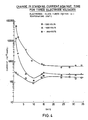
- the base current was measured in an atmosphere of argon over a range of different voltages at temperatures of 150°C, 200°C, and 250°C. The results are illustrated in the curves of FIG. 2(a). These experiments were repeated utilizing soda glass and quartz for the tube 10. Essentially similar results were obtained for the soda glass but no measurable current resulted when utilizing quartz, even in an argon environment. The use of helium in place of argon resulted in a current of approximately the same magnitude from both soda glass and borosilicate glass.
- FIG. 5 The usefulness of this invention as a gas chromatography detector was tested by the apparatus of FIG. 5. It comprised an argon gas supply 28 connected through a septum injector 30 to the inlet end of a packed chromatographic column 32. The outlet end of the column 32 was connected to a detector 34 constructed as illustrated in FIG. 1 and described above. The column 32 and detector 34 were enclosed within a gas chromatograph oven 36. The exit gas from argon detector 34 was connected in series with a flame ionization detector (FID) 38 so that any solute vapor eluted through the system would be monitored by both detectors.
- FID flame ionization detector
- FIG. 6 An example of the dual monitoring of four different hydrocarbons is shown in FIG. 6.
- the response of the argon detector 34 was measured at an electrode potential difference of 900 volts and at temperatures ranging from 100°C to 270°C.
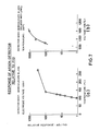
- FIG. 7(a) Shown in FIG. 7(a) are the same results, expressed as the ratio of the height of the peak obtained from the argon detector 34 in millivolts to that obtained from the FID 38 also measured in millivolts.
- the ratio of the noise of the argon detector 34 to that of the FID 38 was also measured and was found to be approximately two orders of magnitude.
- the relative response of the argon detector 34 to that of the FID 38 was also measured for the lithium nitrate treated glass.
- the detector 34 was held at a temperature of 200°C and the electrode voltage varied between 950 volts and 1100 volts.
- the results, expressed as the ratio of the peak height obtained from the argon detector 34 to that from the FID 38, plotted against electrode voltage are shown in FIG. 7(b).
- the ratio of the noise from the argon detector 34 to that of the FID 38 remained at about two orders of magnitude.
- the linearity of the response of the argon detector 34 relative to that of the FID 38 was determined by measuring the peak heights obtained from both detectors for a range of different charges of benzene.
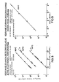
- An untreated borosilicate tube was employed in the first instance at an electrode voltage of 900 volts. The measurements were carried out at detector temperatures of 100°C, 150°C and 180°C. The results obtained are shown in FIG. 7 as curves relating the logarithm of the peak height obtained from the argon detector 34 to the logarithm of that obtained from the FID 38 for each of the three temperatures.
- the linearity of the response of the argon detector 34 with lithium nitrate treated glass was also determined in absolute units.
- the solute was n-decane and different masses were injected into the packed column 32 and the peak heights obtained from the argon detector 34 measured.
- the electrode voltage was 1100 volts and the detector temperature was 150°C.
- the results obtained are shown in FIG. 9 as curves relating the logarithms of the peak heights to the logarithms of the n-decane concentrations.
- the performance of the argon detector 34 when employed to monitor the separation of a high boiling hydrocarbon mixture in the packed column 32 at 200°C is shown in FIG. 10.
- the borosilicate glass tube treated in the described example with lithium nitrate behaved in a very similar manner to the untreated tube, as seen by comparing the results shown in FIG. 2(a) with those shown in FIG. 2(b). From the results in FIG. 3, the lithium nitrate treated tube appeared to have stable properties over 30 days whereas the untreated tube gave widely varying base currents from day-to-day.
- results shown in FIG. 7(a) indicate the very significant increase in response of the argon detector 34 of this invention over that of a conventional FID at elevated temperatures. Those results are from a detector made from a borosilicate glass tube not treated with lithium nitrate. It should also be noted, however, that the noise level was two orders of magnitude greater than that of the FID, giving a signal-to-noise ratio approximately the same as that of the FID.
- the results shown in FIG. 7(b) indicate that the lithium nitrate treated glass, operated at 200°C and at higher electrode voltages, can provide a response three orders of magnitude greater than the FID. Furthermore, as the noise of the argon detector 34 remained only two orders of magnitude greater than that of the FID, the argon detector was exhibiting a sensitivity of at least one order of magnitude greater than the FID. It should be pointed out that this estimate of sensitivity is very conservative as the detector was not electrically screened or grounded in any way, and no attempt was made to minimize noise.
- the curves shown in FIG. 8 have slopes of .999, .986, and .994 at temperatures of 100°C, 150°C and 180°C, respectively. Consequently, assuming the linearity of the FID, the response of the argon detector, employing untreated borosilicate glass was linear over at least two orders of magnitude of solute concentration.
- the curves shown in FIG. 9 are more significant, as they relate argon detector response to the actual concentration of solute injected.
- the curve in FIG. 9 is for the argon detector 34 with lithium nitrate treated borosilicate glass; the slope of the curve is .967, indicating a true linear response over a concentration range covering at least three orders of magnitude. Furthermore, the lowest concentration injected was far from the minimum detectable concentration and so the linear dynamic range is likely to be closer to four orders of magnitude, possibly even five.
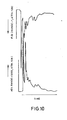
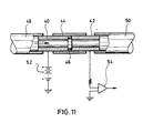
- FIG. 11 illustrates a modified version of a noble gas detector in accordance with the present invention. It comprises a pair of glass tubes 40, 42 which are held in alignment by PTFE sleeve 44, their ends being separated by a washer 46 of PTFE or other non-conductive material such as quartz or fused silica.
- the ID of washer 46 is larger than that of the walls of the glass tubes so that areas of the separated glass ends face each other.
- the gap between the ends created by washer 46 is preferably 0.5-1.0 mm.
- An inlet tube 48 and an outlet tube 50 permit the passage of effluent from a chromatographic column therethrough as shown by the arrow.
- the two glass tubes 40, 42 are connected in series with a power supply 52 and an amplifier 54 supplying a recorder (not shown).
- the power supply may be 1,000-2,000 volts.
- the detector of FIG. 10 has been found to be operable with both argon and helium at temperatures at least as low as 120°C.
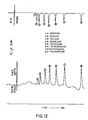
- FIG. 12 is a reproduction of a chromatogram obtained from a helium detector operating at a temperature of 180°C and a voltage of 1,700 volts. It is compared with the output of a flame ionization detector as previously described relative to FIG. 5.
- a noble gas detector employing the evolution of electrons in a glass envelope at elevated temperatures, has been shown to function satisfactorily as a gas chromatograph detector. Detector sensitivity appears to be an order of magnitude greater than that of a flame ionization detector with a linear dynamic range approaching four orders of magnitude. It will be obvious that a number of detector geometries may be employed. In this way, a detector of very small volume may be constructed suitable for direct in-line use with capillary columns. Furthermore, the detector may be constructed entirely of non-metallic materials such as glass and PTFE and is, accordingly, a very inert device. This could be of significant advantage.
- the evolution of electrons within a glass envelope at elevated temperatures has been confirmed, and this effect has been used to build and operate a noble gas detector with both argon and helium.
- the detector provided a linear response over at least three orders of magnitude and exhibited a sensitivity of at least one order of magnitude greater than that of a flame ionization detector. It exhibited sensitivity and linearity adequate for general use in gas chromatography and, at the same time, utilized a simplified pneumatic gas supply. This provides a basis for additional reduction in instrument cost.
Landscapes
- Chemical & Material Sciences (AREA)
- Analytical Chemistry (AREA)
- Physics & Mathematics (AREA)
- Health & Medical Sciences (AREA)
- Life Sciences & Earth Sciences (AREA)
- Biochemistry (AREA)
- General Health & Medical Sciences (AREA)
- General Physics & Mathematics (AREA)
- Immunology (AREA)
- Pathology (AREA)
- Electrochemistry (AREA)
- Chemical Kinetics & Catalysis (AREA)
- Other Investigation Or Analysis Of Materials By Electrical Means (AREA)
Applications Claiming Priority (4)
| Application Number | Priority Date | Filing Date | Title |
|---|---|---|---|
| US85248986A | 1986-04-16 | 1986-04-16 | |
| US852489 | 1987-01-09 | ||
| US4810 | 1987-01-09 | ||
| US07/004,810 US4873862A (en) | 1986-04-16 | 1987-01-09 | Ionization detectors for gas chromatography |
Publications (3)
| Publication Number | Publication Date |
|---|---|
| EP0249714A2 true EP0249714A2 (de) | 1987-12-23 |
| EP0249714A3 EP0249714A3 (en) | 1989-09-06 |
| EP0249714B1 EP0249714B1 (de) | 1992-06-17 |
Family
ID=26673507
Family Applications (1)
| Application Number | Title | Priority Date | Filing Date |
|---|---|---|---|
| EP87105713A Expired EP0249714B1 (de) | 1986-04-16 | 1987-04-16 | Ionisationsdetektoren für die Gaschromatographie |
Country Status (4)
| Country | Link |
|---|---|
| US (1) | US4873862A (de) |
| EP (1) | EP0249714B1 (de) |
| JP (1) | JP2574289B2 (de) |
| DE (1) | DE3779818T2 (de) |
Families Citing this family (6)
| Publication number | Priority date | Publication date | Assignee | Title |
|---|---|---|---|---|
| US5554540A (en) * | 1995-01-19 | 1996-09-10 | Hewlett-Packard Company | Method and apparatus for preserving the sensitivity of a thermionic ionization detector |
| EP0723153B1 (de) * | 1995-01-23 | 2002-08-07 | Agilent Technologies, Inc. (a Delaware corporation) | Strömungsmodulation zur Vereinfachung einer Detektorzündung |
| US5853664A (en) * | 1996-06-25 | 1998-12-29 | Hewlett-Packard Company | Flow modulation for facilitating detector ignition |
| US5955886A (en) * | 1997-07-10 | 1999-09-21 | Pcp, Inc. | Microliter-sized ionization device and method |
| US5892364A (en) * | 1997-09-11 | 1999-04-06 | Monagle; Matthew | Trace constituent detection in inert gases |
| GB2428391B (en) * | 2004-03-29 | 2008-10-29 | Waters Investments Ltd | A capillar emitter for electrospray mass spectrometry |
Family Cites Families (8)
| Publication number | Priority date | Publication date | Assignee | Title |
|---|---|---|---|---|
| NL241857A (de) * | 1958-08-20 | |||
| FR1316810A (fr) * | 1961-03-14 | 1963-02-01 | Hitachi Ltd | Appareil pour l'analyse chromatographique des gaz |
| NL287717A (de) * | 1962-02-13 | |||
| US3751968A (en) * | 1971-01-22 | 1973-08-14 | Inficon Inc | Solid state sensor |
| US4063156A (en) * | 1976-02-27 | 1977-12-13 | Varian Associates, Inc. | Assymetric cylinder electron capture detector |
| US4527064A (en) * | 1980-10-29 | 1985-07-02 | The United States Of America As Represented By The United States Department Of Energy | Imaging alpha particle detector |
| DE3215059A1 (de) * | 1981-06-25 | 1983-01-20 | Westinghouse Electric Corp., 15222 Pittsburgh, Pa. | Lithiummetalldetektor |
| US4500786A (en) * | 1982-04-21 | 1985-02-19 | California Institute Of Technology | Large area spark chamber and support, and method of recording and analyzing the information on a radioactive work piece |
-
1987
- 1987-01-09 US US07/004,810 patent/US4873862A/en not_active Expired - Lifetime
- 1987-04-16 DE DE8787105713T patent/DE3779818T2/de not_active Expired - Lifetime
- 1987-04-16 JP JP62092138A patent/JP2574289B2/ja not_active Expired - Lifetime
- 1987-04-16 EP EP87105713A patent/EP0249714B1/de not_active Expired
Also Published As
| Publication number | Publication date |
|---|---|
| DE3779818T2 (de) | 1992-12-24 |
| EP0249714A3 (en) | 1989-09-06 |
| EP0249714B1 (de) | 1992-06-17 |
| JPS6319550A (ja) | 1988-01-27 |
| US4873862A (en) | 1989-10-17 |
| DE3779818D1 (de) | 1992-07-23 |
| JP2574289B2 (ja) | 1997-01-22 |
Similar Documents
| Publication | Publication Date | Title |
|---|---|---|
| Rhodes et al. | Analysis of polyaromatic hydrocarbon mixtures with laser ionization gas chromatography/mass spectrometry | |
| Fujii et al. | New sensitive and selective detector for gas chromatography: surface ionization detector with a hot platinum emitter | |
| Deal et al. | Radiological Detector for Gas Chromatography | |
| US3247375A (en) | Gas analysis method and device for the qualitative and quantitative analysis of classes of organic vapors | |
| US5019517A (en) | System, detector and method for trace gases | |
| EP0249714B1 (de) | Ionisationsdetektoren für die Gaschromatographie | |
| EP0184892B1 (de) | Ionisationsdetektor für die Gaschromatographie und Analyseverfahren hierzu | |
| US3046396A (en) | Method and apparatus for detection of gases and vapors | |
| Poole | Conventional detectors for gas chromatography | |
| EP0286757B1 (de) | Chromatographischer Dünnschicht-Flammionisationsdetektor für die mengenmässige Analyse von chromatographisch getrennten Substanzen | |
| US3322500A (en) | Fragmentation apparatus for characterization of sample compositions | |
| Colón et al. | Detectors in modern gas chromatography | |
| Louis et al. | Evaluation of direct axial sample introduction for ion mobility detection after capillary gas chromatography | |
| Grimsrud et al. | Stoichiometry of the reaction of electrons with bromotrichloromethane in an electron capture detector | |
| Lovelock et al. | A new approach to lead alkyl analysis: Gas phase electron absorption for selective detection | |
| US3185845A (en) | Method of and apparatus for analyzing chemical compounds | |
| Sullivan et al. | Non-linearity in constant current electron capture detection | |
| Scott | Gas chromatography detectors | |
| US4721858A (en) | Variable pressure ionization detector for gas chromatography | |
| Beres et al. | A new type of argon ionisation detector | |
| Arnikar et al. | The use of an electrodeless discharge as a detector in gas chromatography | |
| US4273559A (en) | Elemental superselective gas chromatographic detection apparatus and method | |
| SU1173292A1 (ru) | Способ ионизационного детектировани примесей в газах | |
| Ongkiehong | The hydrogen flame ionization detector | |
| Hill Jr et al. | Ambient pressure ionization detectors for gas chromatography Part II: Radioactive source ionization detectors |
Legal Events
| Date | Code | Title | Description |
|---|---|---|---|
| PUAI | Public reference made under article 153(3) epc to a published international application that has entered the european phase |
Free format text: ORIGINAL CODE: 0009012 |
|
| AK | Designated contracting states |
Kind code of ref document: A2 Designated state(s): DE FR GB IT NL SE |
|
| ITCL | It: translation for ep claims filed |
Representative=s name: ING. A. GIAMBROCONO & C. S.R.L. |
|
| PUAL | Search report despatched |
Free format text: ORIGINAL CODE: 0009013 |
|
| AK | Designated contracting states |
Kind code of ref document: A3 Designated state(s): DE FR GB IT NL SE |
|
| 17P | Request for examination filed |
Effective date: 19890905 |
|
| 17Q | First examination report despatched |
Effective date: 19901001 |
|
| GRAA | (expected) grant |
Free format text: ORIGINAL CODE: 0009210 |
|
| ITTA | It: last paid annual fee | ||
| AK | Designated contracting states |
Kind code of ref document: B1 Designated state(s): DE FR GB IT NL SE |
|
| ITF | It: translation for a ep patent filed | ||
| REF | Corresponds to: |
Ref document number: 3779818 Country of ref document: DE Date of ref document: 19920723 |
|
| ET | Fr: translation filed | ||
| PLBE | No opposition filed within time limit |
Free format text: ORIGINAL CODE: 0009261 |
|
| STAA | Information on the status of an ep patent application or granted ep patent |
Free format text: STATUS: NO OPPOSITION FILED WITHIN TIME LIMIT |
|
| 26N | No opposition filed | ||
| EAL | Se: european patent in force in sweden |
Ref document number: 87105713.9 |
|
| REG | Reference to a national code |
Ref country code: GB Ref legal event code: 732E |
|
| PGFP | Annual fee paid to national office [announced via postgrant information from national office to epo] |
Ref country code: GB Payment date: 20010330 Year of fee payment: 15 |
|
| PGFP | Annual fee paid to national office [announced via postgrant information from national office to epo] |
Ref country code: FR Payment date: 20010418 Year of fee payment: 15 Ref country code: DE Payment date: 20010418 Year of fee payment: 15 |
|
| PGFP | Annual fee paid to national office [announced via postgrant information from national office to epo] |
Ref country code: NL Payment date: 20010419 Year of fee payment: 15 |
|
| PGFP | Annual fee paid to national office [announced via postgrant information from national office to epo] |
Ref country code: SE Payment date: 20010420 Year of fee payment: 15 |
|
| REG | Reference to a national code |
Ref country code: GB Ref legal event code: IF02 |
|
| PG25 | Lapsed in a contracting state [announced via postgrant information from national office to epo] |
Ref country code: GB Free format text: LAPSE BECAUSE OF NON-PAYMENT OF DUE FEES Effective date: 20020416 |
|
| PG25 | Lapsed in a contracting state [announced via postgrant information from national office to epo] |
Ref country code: SE Free format text: LAPSE BECAUSE OF NON-PAYMENT OF DUE FEES Effective date: 20020417 |
|
| PG25 | Lapsed in a contracting state [announced via postgrant information from national office to epo] |
Ref country code: NL Free format text: LAPSE BECAUSE OF NON-PAYMENT OF DUE FEES Effective date: 20021101 Ref country code: DE Free format text: LAPSE BECAUSE OF NON-PAYMENT OF DUE FEES Effective date: 20021101 |
|
| EUG | Se: european patent has lapsed |
Ref document number: 87105713.9 |
|
| GBPC | Gb: european patent ceased through non-payment of renewal fee |
Effective date: 20020416 |
|
| PG25 | Lapsed in a contracting state [announced via postgrant information from national office to epo] |
Ref country code: FR Free format text: LAPSE BECAUSE OF NON-PAYMENT OF DUE FEES Effective date: 20021231 |
|
| NLV4 | Nl: lapsed or anulled due to non-payment of the annual fee |
Effective date: 20021101 |
|
| REG | Reference to a national code |
Ref country code: FR Ref legal event code: ST |
|
| PG25 | Lapsed in a contracting state [announced via postgrant information from national office to epo] |
Ref country code: IT Free format text: LAPSE BECAUSE OF NON-PAYMENT OF DUE FEES;WARNING: LAPSES OF ITALIAN PATENTS WITH EFFECTIVE DATE BEFORE 2007 MAY HAVE OCCURRED AT ANY TIME BEFORE 2007. THE CORRECT EFFECTIVE DATE MAY BE DIFFERENT FROM THE ONE RECORDED. Effective date: 20050416 |