EP0249539B1 - Fahrzeugaufhängung für Doppelradlaufwerke, zurückfedernde Anordnung von jedem Rad des Laufwerks und Fahrzeug, das mit einer solchen Aufhängung oder zurückfedernden Anordnung ausgerüstet ist - Google Patents
Fahrzeugaufhängung für Doppelradlaufwerke, zurückfedernde Anordnung von jedem Rad des Laufwerks und Fahrzeug, das mit einer solchen Aufhängung oder zurückfedernden Anordnung ausgerüstet ist Download PDFInfo
- Publication number
- EP0249539B1 EP0249539B1 EP19870401261 EP87401261A EP0249539B1 EP 0249539 B1 EP0249539 B1 EP 0249539B1 EP 19870401261 EP19870401261 EP 19870401261 EP 87401261 A EP87401261 A EP 87401261A EP 0249539 B1 EP0249539 B1 EP 0249539B1
- Authority
- EP
- European Patent Office
- Prior art keywords
- vehicle
- wheel
- curved blade
- suspension
- arm
- Prior art date
- Legal status (The legal status is an assumption and is not a legal conclusion. Google has not performed a legal analysis and makes no representation as to the accuracy of the status listed.)
- Expired - Lifetime
Links
- 239000000725 suspension Substances 0.000 title claims description 27
- 239000002131 composite material Substances 0.000 claims description 3
- 230000003247 decreasing effect Effects 0.000 claims description 3
- 229920003002 synthetic resin Polymers 0.000 claims description 3
- 239000000057 synthetic resin Substances 0.000 claims description 3
- 239000000835 fiber Substances 0.000 claims 1
- 229920001971 elastomer Polymers 0.000 description 2
- 239000000806 elastomer Substances 0.000 description 2
- 230000002787 reinforcement Effects 0.000 description 2
Images


Classifications
-
- B—PERFORMING OPERATIONS; TRANSPORTING
- B60—VEHICLES IN GENERAL
- B60G—VEHICLE SUSPENSION ARRANGEMENTS
- B60G11/00—Resilient suspensions characterised by arrangement, location or kind of springs
- B60G11/02—Resilient suspensions characterised by arrangement, location or kind of springs having leaf springs only
- B60G11/10—Resilient suspensions characterised by arrangement, location or kind of springs having leaf springs only characterised by means specially adapted for attaching the spring to axle or sprung part of the vehicle
- B60G11/107—Sliding or rolling mountings
-
- F—MECHANICAL ENGINEERING; LIGHTING; HEATING; WEAPONS; BLASTING
- F16—ENGINEERING ELEMENTS AND UNITS; GENERAL MEASURES FOR PRODUCING AND MAINTAINING EFFECTIVE FUNCTIONING OF MACHINES OR INSTALLATIONS; THERMAL INSULATION IN GENERAL
- F16F—SPRINGS; SHOCK-ABSORBERS; MEANS FOR DAMPING VIBRATION
- F16F1/00—Springs
- F16F1/02—Springs made of steel or other material having low internal friction; Wound, torsion, leaf, cup, ring or the like springs, the material of the spring not being relevant
- F16F1/18—Leaf springs
- F16F1/26—Attachments or mountings
-
- B—PERFORMING OPERATIONS; TRANSPORTING
- B60—VEHICLES IN GENERAL
- B60G—VEHICLE SUSPENSION ARRANGEMENTS
- B60G2202/00—Indexing codes relating to the type of spring, damper or actuator
- B60G2202/10—Type of spring
- B60G2202/11—Leaf spring
- B60G2202/116—Leaf spring having a "C" form loaded only at its ends transversally to its central axis
-
- F—MECHANICAL ENGINEERING; LIGHTING; HEATING; WEAPONS; BLASTING
- F16—ENGINEERING ELEMENTS AND UNITS; GENERAL MEASURES FOR PRODUCING AND MAINTAINING EFFECTIVE FUNCTIONING OF MACHINES OR INSTALLATIONS; THERMAL INSULATION IN GENERAL
- F16F—SPRINGS; SHOCK-ABSORBERS; MEANS FOR DAMPING VIBRATION
- F16F2224/00—Materials; Material properties
- F16F2224/02—Materials; Material properties solids
- F16F2224/0241—Fibre-reinforced plastics [FRP]
Definitions
- the present invention relates to a suspension for a train of two wheels of a vehicle, an elastic return system for each wheel of the train, as well as a vehicle equipped with at least one such suspension or at least one such system of elastic reminder.
- the suspension according to the invention is very particularly, although not exclusively, suitable for use as the rear suspension of a motor vehicle of the front-wheel drive type.
- Suspensions are already known comprising two arms articulated to said vehicle and able to oscillate about an axis transverse to said vehicle, each arm carrying one of said wheels, elastic means being associated with said arms to counteract the vertical movements of said wheels.
- the elastic means generally consist of helical or straight leaf springs, or torsion bars.
- the present invention aims to avoid these drawbacks, and in particular relates to a suspension in which the elastic means are designed in such a way that they have a reduced bulk and that they do not require the use of particular reinforcements, all retaining the advantages and properties of conventional means.
- said elastic means comprise, for each wheel, at least one curved blade connected, at a first end, to the swinging arm corresponding to the neighborhood from the end of the latter articulated to said vehicle, and connected, at its second end, to the vehicle.
- said curved blade is rigidly fixed to the swinging arm and is articulated to the vehicle.
- said curved blade extends at least substantially concentrically with the axis of the wheel while being disposed in front of the latter; in particular, it extends over an angle whose apex is substantially coincident with the center of the wheel and whose amplitude is substantially equal to 90 ° .
- the first end of said curved blade is shaped in a loop and is fixed to the swinging arm so that said loop is coaxial with the axis of articulation of the arm on the chassis and, in in particular, at its end articulated to the chassis, the arm ends in a sleeve on which is fixed said loop forming the first end of the blade.
- This sleeve can serve as a passage for an anti-roll torsion bar connecting the two wheels of the train.
- the present invention also relates to an elastic return system of a wheel of a train of two wheels, of a vehicle equipped with a suspension comprising two arms which can oscillate around an axis transverse to said vehicle and each carrying one said wheels, which is remarkable, according to the invention, in that it comprises at least one curved blade intended to be connected, at a first end, to the oscillating arm corresponding to the vicinity of the end of the latter articulated to said vehicle, and, at its second end, to the vehicle.
- said curved blade comprises, at its first end, fixing means making it possible to rigidly fix it to the swinging arm, and said curved blade comprises, at its second end, articulation means making it possible to articulate it to the vehicle.
- said curved blade has a progressively decreasing section from its end intended to be connected to the oscillating arm to its end intended to be connected to the vehicle.
- said curved blade is made of composite fiber-synthetic resins.
- each arm 1 is fixed to a wheel 2 by conventional fixing means 3, while the other end 1b of the arm 1 is articulated to a fastener 4 secured to the chassis 5 of the vehicle (not shown) by means of an elastomeric frame 6 only visible in FIG. 3.
- each arm 1 is connected to the chassis 5 by means of a telescopic damper 7 which is articulated at 8 to the arm 1 and fixed by a link 9 to the chassis 5.
- the two wheels of the tran are connected by an anti-tilt torsion bar 10, each end of which is inserted and fixed in the tubular end 1b, produced in this example in the form of a sleeve 30, connected to the chassis 5 , of one of the arms 1.
- Each wheel 2 is thus capable of vertical deflection around the articulation of the arm 1 to the chassis 5.
- a curved blade 11 serves as elastic means, associated with each suspension arm 1, to counteract the vertical movements of the corresponding wheel 2.
- the curved blade 11 is connected, at a first end 12, to the oscillating arm 1 in the vicinity of the end tee 1 b of the latter articulated to the chassis 5, and is connected, at its second end 13, to the chassis 5 of the vehicle.
- the curved blade 11 which is advantageously made of composite fiber-synthetic resins, extends at least substantially concentrically to the axis 2a of the wheel while being disposed at the front of the latter and this at an angle whose apex is substantially coincident with the center of the wheel and whose amplitude is substantially equal to 90 ° .
- the blade 11 may have a constant section (FIG. 1) or progressively decreasing from its end 12 connected to the swinging arm 1 to its end 13 connected to the chassis 5 of the vehicle (exemplary embodiment illustrated by FIGS. 2 and 3 ).
- the particular geometry of the blade will be adapted to the desired longitudinal variation in stiffness.
- the curved blade 11 comprises, at its first end 12, fixing means making it possible to rigidly fix it to the swinging arm 1 and, at its second end 13, articulation means making it possible to articulate it to the chassis 5 of the vehicle.
- the blade 11 is fixed, at its first end 12, to the swinging arm 1 by means of a retaining plate 14 which is fixed to the arm 1 by means of bolts 15 passing through the blade 11.
- the blade 11 is articulated to the chassis 5 while being mounted on an axis 16 carried by a yoke 17 fixed to the chassis.
- the blade 11, reinforced with hoops 18, has, at its first end 12, an orifice 19 through which the end 1b of the arm 1 passes.
- the first end 12, shaped as a loop, of the blade 11 is thus fixed to the sleeve 30 of the arm 1 while being coaxial with the axis of articulation XX 'of the arm 1 on the chassis 5.
- the blade 11 is mounted in an elastomer support bearing 20 fixed to the chassis 5.
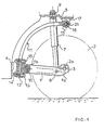
- FIG. 4 An alternative embodiment (FIG. 4) consists in hinging the blade 11, at this end 13, to the chassis 5 by means of an axis 16a carried by a yoke 17a fixed to the chassis 5, as in the illustrated embodiment by figure 1.
Landscapes
- Engineering & Computer Science (AREA)
- Mechanical Engineering (AREA)
- General Engineering & Computer Science (AREA)
- Vehicle Body Suspensions (AREA)
- Springs (AREA)
Claims (11)
Applications Claiming Priority (2)
| Application Number | Priority Date | Filing Date | Title |
|---|---|---|---|
| FR8608283A FR2599676B1 (fr) | 1986-06-09 | 1986-06-09 | Suspension pour un train de deux roues d'un vehicule, systeme de rappel elastique de chaque roue du train et vehicule equipe d'une telle suspension ou d'un tel systeme de rappel elastique |
| FR8608283 | 1986-06-09 |
Publications (2)
| Publication Number | Publication Date |
|---|---|
| EP0249539A1 EP0249539A1 (de) | 1987-12-16 |
| EP0249539B1 true EP0249539B1 (de) | 1990-11-07 |
Family
ID=9336133
Family Applications (1)
| Application Number | Title | Priority Date | Filing Date |
|---|---|---|---|
| EP19870401261 Expired - Lifetime EP0249539B1 (de) | 1986-06-09 | 1987-06-04 | Fahrzeugaufhängung für Doppelradlaufwerke, zurückfedernde Anordnung von jedem Rad des Laufwerks und Fahrzeug, das mit einer solchen Aufhängung oder zurückfedernden Anordnung ausgerüstet ist |
Country Status (3)
| Country | Link |
|---|---|
| EP (1) | EP0249539B1 (de) |
| DE (1) | DE3766014D1 (de) |
| FR (1) | FR2599676B1 (de) |
Families Citing this family (4)
| Publication number | Priority date | Publication date | Assignee | Title |
|---|---|---|---|---|
| JPH02503783A (ja) * | 1988-04-14 | 1990-11-08 | キエフスキー、インゼネルノ‐ストロイチェルヌイ、インスチツート | オートバイの車輪懸架装置 |
| DD292509A5 (de) * | 1990-03-14 | 1991-08-01 | Veb Kraftfahrzeugwerk "Ernst Grube",De | Gfk-blattfeder |
| FR2701431B1 (fr) * | 1993-02-15 | 1995-05-05 | Bertin & Cie | Suspension pour roue de véhicule tel qu'une remorque et ensemble de telles suspensions. |
| FR2761302B1 (fr) * | 1997-03-28 | 1999-06-18 | Peugeot | Perfectionnement a un essieu arriere pour vehicule automobile du type a traverse deformable en torsion et a ressorts de suspension sensiblement verticaux |
Family Cites Families (6)
| Publication number | Priority date | Publication date | Assignee | Title |
|---|---|---|---|---|
| GB198703A (en) * | 1921-11-26 | 1923-05-28 | James Booth | Improvements in spring suspensions for motor vehicles |
| US1938847A (en) * | 1932-06-17 | 1933-12-12 | Int Motor Co | Torsional spring suspension for individually sprung wheels |
| FR975621A (fr) * | 1942-03-13 | 1951-03-07 | Perfectionnements apportés à un dispositif de suspension pour roues de véhicules notamment à ceux pour roue directrice unique de véhicules automobiles à trois roues | |
| US4027898A (en) * | 1976-04-07 | 1977-06-07 | Southwest Wheel And Manufacturing Company | Level load leaf spring drop axle |
| US4560525A (en) * | 1983-10-19 | 1985-12-24 | A. O. Smith Corporation | Method of making a molded fiber reinforced plastic leaf spring |
| FR2574028B1 (fr) * | 1984-11-30 | 1988-12-09 | Peugeot | Suspension pour vehicules automobiles |
-
1986
- 1986-06-09 FR FR8608283A patent/FR2599676B1/fr not_active Expired - Fee Related
-
1987
- 1987-06-04 DE DE8787401261T patent/DE3766014D1/de not_active Expired - Fee Related
- 1987-06-04 EP EP19870401261 patent/EP0249539B1/de not_active Expired - Lifetime
Also Published As
| Publication number | Publication date |
|---|---|
| EP0249539A1 (de) | 1987-12-16 |
| DE3766014D1 (de) | 1990-12-13 |
| FR2599676B1 (fr) | 1990-08-03 |
| FR2599676A1 (fr) | 1987-12-11 |
Similar Documents
| Publication | Publication Date | Title |
|---|---|---|
| EP0156705B1 (de) | Schwinghebelaufhängung für einen Fahrzeugradsatz mit zwei Rädern und Zusammenbau der Parallelröhren für eine derartige Aufhängung | |
| EP0094295B1 (de) | Längslenkeraufhängung für eine Zweiräderachse eines Kraftfahrzeuges | |
| FR2662118A1 (fr) | Train arriere d'un vehicule automobile. | |
| EP0097540A1 (de) | Längslenkeraufhängung für eine Zweiräderachse eines Kraftfahrzeuges mit Querstabilisator und elastischer Federung | |
| FR2720691A1 (fr) | Suspension pour un essieu arrière. | |
| FR2481198A1 (fr) | Essieu arriere pour vehicule, notamment pour automobile | |
| FR2462283A1 (fr) | Suspension a essieu rigide pour vehicules automobiles, assurant un confort analogue aux dispositifs a roues independantes | |
| EP0389363B1 (de) | Kraftfahrzeughinterradsatz | |
| FR2464837A1 (fr) | Train avant de vehicule automobile | |
| EP0249539B1 (de) | Fahrzeugaufhängung für Doppelradlaufwerke, zurückfedernde Anordnung von jedem Rad des Laufwerks und Fahrzeug, das mit einer solchen Aufhängung oder zurückfedernden Anordnung ausgerüstet ist | |
| EP0930183A1 (de) | Hinterradaufhängungsvorrichtung eines Kraftfahrzeuges | |
| FR2691930A1 (fr) | Essieu, notamment essieu arrière multibras de véhicule automobile. | |
| EP0867318A1 (de) | Verbesserungen an einer Hinterachse eines Kraftfahrzeuges mit einem torsionsverformbaren Verbundlenker und vertikalen Aufhängungsfedern | |
| FR2645800A1 (fr) | Train de roues notamment du type mac-pherson a traverse inferieure de filtrage | |
| FR2612460A1 (fr) | Train arriere pour vehicule automobile et vehicule automobile equipe d'un tel train | |
| FR2938794A1 (fr) | Train arriere pour vehicule automobile comprenant deux bras de suspension comportant une ouverture verticale | |
| FR2825340A1 (fr) | Bras oscillant arriere pour motocyclettes | |
| EP1024037B1 (de) | Hinterachsenaufhängung für ein Kraftfahrzeug | |
| FR2720036A1 (fr) | Train avant à doubles triangles transversaux et véhicule automobile équipé d'un tel train. | |
| FR2738190A1 (fr) | Dispositif de suspension pour train de roues arriere de vehicule automobile | |
| FR2702709A1 (fr) | Train arrière de véhicule automobile du type à bras tirés. | |
| FR2941404A1 (fr) | Train arriere pour vehicule automobile comprenant deux ressorts lateraux en materiaux composites | |
| EP0392891B1 (de) | Radaufhängung für Kraftfahrzeuge | |
| FR2691109A1 (fr) | Dispositif formant suspension, notamment pour train arrière de véhicule automobile. | |
| FR2788473A1 (fr) | Train arriere de vehicule automobile a ressort helicoidal et amortisseur de suspension separes |
Legal Events
| Date | Code | Title | Description |
|---|---|---|---|
| PUAI | Public reference made under article 153(3) epc to a published international application that has entered the european phase |
Free format text: ORIGINAL CODE: 0009012 |
|
| AK | Designated contracting states |
Kind code of ref document: A1 Designated state(s): DE GB IT SE |
|
| 17P | Request for examination filed |
Effective date: 19880114 |
|
| 17Q | First examination report despatched |
Effective date: 19900126 |
|
| GRAA | (expected) grant |
Free format text: ORIGINAL CODE: 0009210 |
|
| AK | Designated contracting states |
Kind code of ref document: B1 Designated state(s): DE GB IT SE |
|
| GBT | Gb: translation of ep patent filed (gb section 77(6)(a)/1977) | ||
| REF | Corresponds to: |
Ref document number: 3766014 Country of ref document: DE Date of ref document: 19901213 |
|
| ITF | It: translation for a ep patent filed | ||
| PGFP | Annual fee paid to national office [announced via postgrant information from national office to epo] |
Ref country code: SE Payment date: 19910523 Year of fee payment: 5 |
|
| PGFP | Annual fee paid to national office [announced via postgrant information from national office to epo] |
Ref country code: GB Payment date: 19910528 Year of fee payment: 5 |
|
| PGFP | Annual fee paid to national office [announced via postgrant information from national office to epo] |
Ref country code: DE Payment date: 19910624 Year of fee payment: 5 |
|
| ITTA | It: last paid annual fee | ||
| PLBE | No opposition filed within time limit |
Free format text: ORIGINAL CODE: 0009261 |
|
| STAA | Information on the status of an ep patent application or granted ep patent |
Free format text: STATUS: NO OPPOSITION FILED WITHIN TIME LIMIT |
|
| 26N | No opposition filed | ||
| PG25 | Lapsed in a contracting state [announced via postgrant information from national office to epo] |
Ref country code: GB Effective date: 19920604 |
|
| PG25 | Lapsed in a contracting state [announced via postgrant information from national office to epo] |
Ref country code: SE Effective date: 19920605 |
|
| GBPC | Gb: european patent ceased through non-payment of renewal fee |
Effective date: 19920604 |
|
| PG25 | Lapsed in a contracting state [announced via postgrant information from national office to epo] |
Ref country code: DE Effective date: 19930302 |
|
| EUG | Se: european patent has lapsed |
Ref document number: 87401261.0 Effective date: 19930109 |
|
| PG25 | Lapsed in a contracting state [announced via postgrant information from national office to epo] |
Ref country code: IT Free format text: LAPSE BECAUSE OF NON-PAYMENT OF DUE FEES;WARNING: LAPSES OF ITALIAN PATENTS WITH EFFECTIVE DATE BEFORE 2007 MAY HAVE OCCURRED AT ANY TIME BEFORE 2007. THE CORRECT EFFECTIVE DATE MAY BE DIFFERENT FROM THE ONE RECORDED. Effective date: 20050604 |