EP0248978A2 - Cartridge case - Google Patents
Cartridge case Download PDFInfo
- Publication number
- EP0248978A2 EP0248978A2 EP87102747A EP87102747A EP0248978A2 EP 0248978 A2 EP0248978 A2 EP 0248978A2 EP 87102747 A EP87102747 A EP 87102747A EP 87102747 A EP87102747 A EP 87102747A EP 0248978 A2 EP0248978 A2 EP 0248978A2
- Authority
- EP
- European Patent Office
- Prior art keywords
- stiffening
- propellant charge
- casing
- case according
- sleeve
- Prior art date
- Legal status (The legal status is an assumption and is not a legal conclusion. Google has not performed a legal analysis and makes no representation as to the accuracy of the status listed.)
- Granted
Links
- 239000003380 propellant Substances 0.000 claims abstract description 27
- 238000002485 combustion reaction Methods 0.000 claims abstract description 8
- 239000003351 stiffener Substances 0.000 claims abstract description 8
- 239000002184 metal Substances 0.000 claims abstract description 7
- 239000000020 Nitrocellulose Substances 0.000 claims abstract description 6
- 229920001220 nitrocellulos Polymers 0.000 claims abstract description 6
- 239000004744 fabric Substances 0.000 claims description 2
- 230000000717 retained effect Effects 0.000 abstract description 2
- 230000003014 reinforcing effect Effects 0.000 description 2
- 230000006978 adaptation Effects 0.000 description 1
- 238000005470 impregnation Methods 0.000 description 1
- 238000004519 manufacturing process Methods 0.000 description 1
- 239000000463 material Substances 0.000 description 1
- 239000000843 powder Substances 0.000 description 1
- 230000035939 shock Effects 0.000 description 1
Images

Classifications
-
- F—MECHANICAL ENGINEERING; LIGHTING; HEATING; WEAPONS; BLASTING
- F42—AMMUNITION; BLASTING
- F42B—EXPLOSIVE CHARGES, e.g. FOR BLASTING, FIREWORKS, AMMUNITION
- F42B5/00—Cartridge ammunition, e.g. separately-loaded propellant charges
- F42B5/02—Cartridges, i.e. cases with charge and missile
- F42B5/18—Caseless ammunition; Cartridges having combustible cases
- F42B5/181—Caseless ammunition; Cartridges having combustible cases consisting of a combustible casing wall and a metal base; Connectors therefor
-
- F—MECHANICAL ENGINEERING; LIGHTING; HEATING; WEAPONS; BLASTING
- F42—AMMUNITION; BLASTING
- F42B—EXPLOSIVE CHARGES, e.g. FOR BLASTING, FIREWORKS, AMMUNITION
- F42B5/00—Cartridge ammunition, e.g. separately-loaded propellant charges
- F42B5/02—Cartridges, i.e. cases with charge and missile
- F42B5/18—Caseless ammunition; Cartridges having combustible cases
-
- Y—GENERAL TAGGING OF NEW TECHNOLOGICAL DEVELOPMENTS; GENERAL TAGGING OF CROSS-SECTIONAL TECHNOLOGIES SPANNING OVER SEVERAL SECTIONS OF THE IPC; TECHNICAL SUBJECTS COVERED BY FORMER USPC CROSS-REFERENCE ART COLLECTIONS [XRACs] AND DIGESTS
- Y10—TECHNICAL SUBJECTS COVERED BY FORMER USPC
- Y10S—TECHNICAL SUBJECTS COVERED BY FORMER USPC CROSS-REFERENCE ART COLLECTIONS [XRACs] AND DIGESTS
- Y10S102/00—Ammunition and explosives
- Y10S102/70—Combustilbe cartridge
Definitions
- the invention relates to a propellant charge case according to the preamble of claim 1.
- Propellant charge cases with a cover made of a fleece based on nitrocellulose have the advantage of a small specific weight and the residue-free combustion in weapon tubes under pressure and temperature. Furthermore, there is no "empties" in the fighting rooms, and the CO concentration is very low compared to metal sleeves. However, it is disadvantageous that the inherent strength of this material cannot be increased further without disadvantageously changing the mentioned advantage. This affects the use in particular of ammunition of larger caliber, such as tank ammunition, which is exposed to considerable mechanical stresses from loading and unloading, shock and vibration, since the fleece can be damaged or destroyed at weak points. The consequences are difficulties when loading or unloading or propellant powder that trickles out. All of this poses a threat to the soldier.
- the object of the invention is to provide a propellant charge sleeve according to the preamble of claim 1, in which the mechanical loads to be expected do not cause any damage, but the residue-free combustion of the nonwoven is retained.
- stiffeners for the weak points of the propellant charge sleeve, which are connected to the fleece, do not remain in the gun barrel.
- the stiffeners can be appropriately stored in the tool during manufacture.
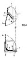
- a floor 1 with sabot 2 is shown, which is connected via a seal 3 to a propellant charge sleeve 4.
- the propellant charge sleeve 4 has a metallic, reusable base 5 with a bore 6 for receiving a primer 7.
- the propellant charge sleeve 4 also has a sleeve 8 made of a fleece based on nitrocellulose.
- the casing 8 has, next to the seal 3, a curved section 9 which is extended to a bore 10 through which the projectile 1 extends.
- the area 9 can also have an angular section, for example when a projectile 1 is received without a sabot through Propellant charge sleeve 4.
- the sleeve 8 has a curved section 11 in the base region in adaptation to the curvature of the base 5, which extends on the base side to the central pin 12 of the base, which contains the bore 6.
- Sections 9, 11 and the sections around the bore 10 and the central pin 12 are weak points of the casing 8 which are endangered by mechanical stresses. Accordingly, stiffeners 13 made of metal or plastic are provided in these areas.
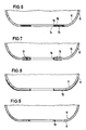
- the stiffener 13 consists of a perforated insert made of sheet metal or plastic. Since the base 5 protects the casing 8 in the area 11, the stiffening 13 can optionally also be provided only around the bore 14 surrounding the central pin 12, as shown in FIG. 3. If necessary, a stiffening 13 in the form of a reinforcing ring at this point, as shown in FIG. 9, is sufficient.
- the stiffening 13 of the embodiments of FIGS. 2 and 3 has an inner ring 15 delimiting the bore 14.
- the stiffening 13 is not designed as an insert, as in FIGS. 2 and 3, but rather as a support, which is glued onto the casing 8 from the outside or, as shown in the left half of FIG. 4 is attached by curling.
- the stiffening 13 can be inserted into the suction tool for producing the casing 8. Since in the embodiment of FIG. 4 the stiffening 13 is only on the outside of the casing 8, no openings in the stiffening 13 are required here, since the residue-free combustion of the casing 8 is ensured.
- the cross-sectionally L-shaped stiffening 13 is incorporated into the wall of the casing 8, so that the casing 8 has essentially the same wall thickness everywhere.
- the recess required for this is made by mechanical processing. Since, as a result of this mechanical processing, that area of the casing 8 which has the greatest strength and density area is removed, while the felted central area of the casing 8 remains, re-impregnation of the remaining part of the casing 8 is available Appropriate the same.
- the stiffening 13 is clamped around the casing 8 in the region of the bore 14, the stiffening 13 having holes 16 at least on the inside in order to ensure residue-free combustion of the casing 8.
- the stiffening 13 is arranged flush with the outer sides of the casing 8 and the casing 8 is expediently impregnated in this area.
- rivet or screw connections 17 can also be used to fasten the U-shaped stiffener 13 in section.
- the stiffening 13 can also consist of fabric made of metal or plastic, as indicated in FIG. 8.
Landscapes
- Engineering & Computer Science (AREA)
- General Engineering & Computer Science (AREA)
- Connection Of Plates (AREA)
- Insertion Pins And Rivets (AREA)
- Valve Device For Special Equipments (AREA)
- Liquid Crystal (AREA)
- Extraction Or Liquid Replacement (AREA)
- Portable Nailing Machines And Staplers (AREA)
- Moulding By Coating Moulds (AREA)
- Aiming, Guidance, Guns With A Light Source, Armor, Camouflage, And Targets (AREA)
Abstract
Die Erfindung betrifft eine Treibladungshülse (4) mit einer Hülle (8) aus einem Vlies auf Nitrozellulose-Basis. Damit mechanische Beanspruchungen zu keinen Beschädigungen führen und trotzdem die rückstandsfreie Verbrennung der Hülle (8) erhalten bleibt, ist vorgesehen, daß im Bereich von gekrümmten, im Schnitt winkelförmigen und/oder eine Bohrung (6, 10) umgebenden Abschnitten (9, 11) der Hülle (8) eine Versteifung (13) aus Metall oder Kunststoff in der Hülle (8) eingebettet oder auf der Hülle (8) befestigt ist, wobei die Versteifung (13) eine die rückstandsfreie Verbrennung des Vlieses nicht beeinträchtigende Gestaltung besitzt. 
Description
Die Erfindung betrifft eine Treibladungshülse nach dem Oberbegriff des Anspruchs 1.The invention relates to a propellant charge case according to the preamble of claim 1.
Aus der DE-AS 14 46 889 ist es bekannt, Treibladungshülsen auf der Basis von Nitrozellulose herzustellen, wobei auf einem Ansaugwerkzeug ein Vlies erzeugt wird, das nach seiner Trocknung zusätzlich imprägniert wird.From DE-AS 14 46 889 it is known to produce propellant charge sleeves based on nitrocellulose, a fleece being produced on a suction tool which is additionally impregnated after it has dried.
Ferner ist es aus der DE-PS 14 53 842 bekannt, für eine Treibladungshülse eine rohrförmige Hülle aus einem Vlies auf Nitrozellulose-Basis zu verwenden, die zwischen einem äußeren und einem inneren bodenseitig angeordneten Verbindungsbecher eingeklemmt wird, wobei der innere Verbindungsbecher Löcher aufweist, die eine rückstandsfreie Verbrennung des Vlieses sicherstellen. Der äußere Verbindungsbecher wird in einen Boden eingesetzt. Dies erfordert jedoch einen relativ aufwendigen Aufbau der Treibladungshülse im Bodenbereich.Furthermore, it is known from DE-PS 14 53 842 to use a tubular shell made of a fleece based on nitrocellulose for a propellant charge sleeve, which is clamped between an outer and an inner connection cup arranged on the bottom, the inner connection cup having holes which ensure residue-free combustion of the fleece. The outer connection cup is inserted into a floor. However, this requires a relatively complex structure of the propellant charge sleeve in the bottom area.
Zusätzlich ist es an sich etwa aus der DE-PS 34 18 61 bekannt, den Boden von Treibladungshülsen mittels eines Versteifungsrings zu verstärken, während gemäß der DE-OS 15 78 153 bei einer Treibladungshülse für Jagdpatronen ein Metalleinsatz zur Verstärkung des Hülsenbodens und der Öffnung für die Zündkapsel in axialer und radialer Richtung vorgesehen ist.In addition, it is known per se from DE-PS 34 18 61 to reinforce the bottom of propellant charge cases by means of a stiffening ring, while according to DE-OS 15 78 153 a metal insert for reinforcing the case base and the opening for a propellant charge case for hunting cartridges the primer is provided in the axial and radial directions.
Treibladungshülsen mit einer Hülle aus einem Vlies auf Nitrozellulose-Basis besitzen den Vorteil eines kleinen spezifischen Gewichts und der rückstandsfreien Verbrennung in Waffenrohren unter Druck und Temperatur. Ferner fällt in den Kampfräumen kein "Leergut" an, und außerdem ist die CO-Konzentration im Vergleich zu Metallhülsen sehr gering. Nachteilig ist jedoch, daß die Eigenfestigkeit dieses Materials nicht weiter gesteigert werden kann, ohne die genannten Vorteil nachteilig zu verändern. Dies beeinträchtigt die Verwendung insbesondere bei Munition größerer Kaliber, etwa Panzermunition, die erheblichen mechanischen Beanspruchungen durch Laden und Entladen, Schock und Vibration ausgesetzt ist, da hierbei das Vlies an Schwachstellen beschädigt oder zerstört werden kann. Die Folgen sind Schwieri gkeiten beim Laden oder Entladen oder auch herausrieselndes Treibladungspulver. Dies alles stellt eine Gefahr für den Soldaten dar.Propellant charge cases with a cover made of a fleece based on nitrocellulose have the advantage of a small specific weight and the residue-free combustion in weapon tubes under pressure and temperature. Furthermore, there is no "empties" in the fighting rooms, and the CO concentration is very low compared to metal sleeves. However, it is disadvantageous that the inherent strength of this material cannot be increased further without disadvantageously changing the mentioned advantage. This affects the use in particular of ammunition of larger caliber, such as tank ammunition, which is exposed to considerable mechanical stresses from loading and unloading, shock and vibration, since the fleece can be damaged or destroyed at weak points. The consequences are difficulties when loading or unloading or propellant powder that trickles out. All of this poses a threat to the soldier.
Aufgabe der Erfindung ist es, eine Treibladungshülse nach dem Oberbegriff des Anspruchs 1 zu schaffen, bei der die zu erwartenden mechanischen Beanspruchungen keine Beschädigungen hervorrufen, jedoch die rückstandsfreie Verbrennung des Vlieses erhalten bleibt.The object of the invention is to provide a propellant charge sleeve according to the preamble of claim 1, in which the mechanical loads to be expected do not cause any damage, but the residue-free combustion of the nonwoven is retained.
Diese Aufgabe wird entsprechend dem kennzeichnenden Teil des Anspruchs 1 gelöst.This object is achieved in accordance with the characterizing part of claim 1.
Gleichzeitig wird hierdurch sichergestellt, daß die Versteifungen für die Schwachstellen der Treibladungshülse, die mit dem Vlies verbunden sind, nicht im Waffenrohr liegenbleiben. Die Versteifungen können bei der Herstellung entsprechend in das Werkzeug eingelagert werden.At the same time, this ensures that the stiffeners for the weak points of the propellant charge sleeve, which are connected to the fleece, do not remain in the gun barrel. The stiffeners can be appropriately stored in the tool during manufacture.
Weitere Ausgestaltungen der Erfindung sind der nachfolgenden Beschreibung und den Unteransprüchen zu entnehmen.Further embodiments of the invention can be found in the following description and the subclaims.
Die Erfindung wird nachstehend anhand der in den beigefügten Abbildungen dargestellten Ausführungsbeispiele näher erläutert.
- Fig. 1 zeigt ausschnittweise ein Geschoß mit Treibladungshülse im Schnitt.
- Fig. 2 zeigt vergrößert den Bodenbereich der Treibladungshülse von Fig. 1.
- Fig. 3 bis 9 zeigen weitere Ausführungsformen von Treibladungshülsen entsprechend der Darstellung von Fig. 2.
- Fig. 1 shows a section of a projectile with propellant charge sleeve in section.
- FIG. 2 shows an enlarged view of the bottom region of the propellant charge sleeve from FIG. 1.
- 3 to 9 show further embodiments of propellant charge sleeves corresponding to the illustration in FIG. 2.
In Fig. 1 ist ein Geschoß 1 mit Treibkäfig 2 dargestellt, das über eine Dichtung 3 mit einer Treibladungshülse 4 verbunden ist. Die Treibladungshülse 4 besitzt einen metallischen wiederverwendbaren Boden 5 mit einer Bohrung 6 zur Aufnahme einer Zündkapsel 7. Die Treibladungshülse 4 besitzt ferner eine Hülle 8 aus einem Vlies auf Nitrozellulose-Basis. Die Hülle 8 besitzt benachbart zur Dichtung 3 einen gekrümmten Abschnitt 9, der bis zu einer Bohrung 10 verlängert ist, durch die sich das Geschoß 1 erstreckt. Der Bereich 9 kann auch im Schnitt winkelförmig ausgebildet sein, etwa bei Aufnahme eines Geschosses 1 ohne Treibkäfig durch die Treibladungshülse 4. Ferner besitzt die Hülle 8 im Bodenbereich einen gekrümmten Abschnitt 11 in Anpassung an die Krümmung des Bodens 5, der sich bodenseitig bis zum Mittelzapfen 12 des Bodens, der die Bohrung 6 enthält, erstreckt.In Fig. 1 a floor 1 with
Schwachstellen der Hülle 8, die durch mechanische Beanspruchungen gefährdet sind, sind die Abschnitte 9, 11 sowie die Abschnitte um die Bohrung 10 bzw. den Mittelzapfen 12. Dementsprechend sind in diesen Bereichen Versteifungen 13 aus Metall oder Kunststoff vorgesehen.
Bei der in Fig. 2 dargestellten Ausführungsform besteht die Versteifung 13 aus einer gelochten Einlage aus Metallblech oder Kunststoff. Da der Boden 5 die Hülle 8 im Bereich 11 schützt, kann die Versteifung 13 gegebenenfalls auch nur um die den Mittelzapfen 12 umgebende Bohrung 14 herum vorgesehen sein, wie in Fig. 3 dargestellt ist. Gegebenenfalls reicht auch eine Versteifung 13 in Form eines Verstärkungsrings an dieser Stelle, wie sie in Fig. 9 dargestellt ist. Die Versteifung 13 der Ausführungsformen der Figuren 2 und 3 besitzt einen die Bohrung 14 begrenzenden Innenring 15.In the embodiment shown in Fig. 2, the
Bei der in Fig. 4 dargestellten Ausführungsform ist die Versteifung 13 nicht wie bei Fig. 2 und 3 als Einlage, sondern als Auflage ausgebildet, die von der Außenseite auf die Hülle 8 durch Kleben oder, wie in der linken Hälfte von Fig. 4 dargestellt ist, durch Einrollen befestigt ist. Auch hierbei kann die Versteifung 13 in das Ansaugwerkzeug zum Herstellen der Hülle 8 eingelegt werden. Da bei der Ausführungsform von Fig. 4 die Versteifung 13 sich nur außenseitig zur Hülle 8 befindet, benötigt man hier keine Durchbrüche in der Versteifung 13, da die rückstandsfreie Verbrennung der Hülle 8 gewährleistet ist.In the embodiment shown in FIG. 4, the
Bei der in Fig. 5 dargestellten Ausführungsform ist die im Schnitt L-förmige Versteifung 13 in die Wandung der Hülle 8 eingearbeitet, so daß die Hülle 8 überall im wesentlichen gleiche Wandstärke aufweist. Die hierfür notwendige Ausnehmung ist durch mechanische Bearbeitung hergestellt. Da infolg e dieser mechanischen Bearbeitung derjenige Bereich der Hülle 8, der den größten Festigkeits- und Dichtebereich aufweist, entfernt wird, während der filzige Mittelbereich der Hülle 8 verbleibt, ist eine Nachimprägnierung des verbliebenen Teils der Hülle 8 zur Verfe stigung derselben zweckmäßig.In the embodiment shown in Fig. 5, the cross-sectionally L-
Bei der in Fig. 6 dargestellten Ausführungsform ist die Versteifung 13 im Bereich der Bohrung 14 um die Hülle 8 herum geklemmt, wobei zumindest an der Innenseite die Versteifung 13 Löcher 16 aufweist, um eine rückstandsfreie Verbrennung der Hülle 8 zu gewährleisten. Hierbei ist die Versteifung 13 wie bei der Ausführungsform von Fig. 5 bündig mit den Außenseiten der Hülle 8 angeordnet und die Hülle 8 in diesem Bereich zweckmäßigerweise nachimprägniert.In the embodiment shown in FIG. 6, the
Wie Fig. 7 zeigt, können zur Befestigung der im Schnitt U-förmigen Versteifung 13 auch Niet- oder Schraubverbindungen 17 verwendet werden.As shown in FIG. 7, rivet or
Die Versteifung 13 kann auch aus Gewebe aus Metall oder Kunststoff bestehen, wie in Fig. 8 angedeutet ist. The stiffening 13 can also consist of fabric made of metal or plastic, as indicated in FIG. 8.
Claims (9)
Applications Claiming Priority (2)
| Application Number | Priority Date | Filing Date | Title |
|---|---|---|---|
| DE3619960 | 1986-06-13 | ||
| DE19863619960 DE3619960A1 (en) | 1986-06-13 | 1986-06-13 | DRIVE CHARGE |
Publications (3)
| Publication Number | Publication Date |
|---|---|
| EP0248978A2 true EP0248978A2 (en) | 1987-12-16 |
| EP0248978A3 EP0248978A3 (en) | 1988-03-30 |
| EP0248978B1 EP0248978B1 (en) | 1990-06-13 |
Family
ID=6302952
Family Applications (1)
| Application Number | Title | Priority Date | Filing Date |
|---|---|---|---|
| EP87102747A Expired - Lifetime EP0248978B1 (en) | 1986-06-13 | 1987-02-26 | Cartridge case |
Country Status (4)
| Country | Link |
|---|---|
| US (1) | US4928598A (en) |
| EP (1) | EP0248978B1 (en) |
| JP (1) | JPS62297699A (en) |
| DE (2) | DE3619960A1 (en) |
Cited By (2)
| Publication number | Priority date | Publication date | Assignee | Title |
|---|---|---|---|---|
| WO2008080506A1 (en) | 2007-01-04 | 2008-07-10 | Nitrochemie Aschau Gmbh | Molded part, and method for the production of the molded part |
| FR3113728A1 (en) * | 2020-09-01 | 2022-03-04 | Nexter Munitions | Fuel case for ammunition |
Families Citing this family (13)
| Publication number | Priority date | Publication date | Assignee | Title |
|---|---|---|---|---|
| US5048421A (en) * | 1990-08-06 | 1991-09-17 | Olin Corporation | Combustible cartridge case base |
| US5138949A (en) * | 1990-09-20 | 1992-08-18 | Olin Corporation | Combustible ammunition cartridge case |
| US7441504B2 (en) * | 1999-01-15 | 2008-10-28 | Development Capital Management Company | Base for a cartridge casing body for an ammunition article, a cartridge casing body and an ammunition article having such base, wherein the base is made from plastic, ceramic, or a composite material |
| US6752084B1 (en) * | 1999-01-15 | 2004-06-22 | Amtech, Inc. | Ammunition articles with plastic components and method of making ammunition articles with plastic components |
| FR2799831B1 (en) * | 1999-10-13 | 2001-11-30 | Giat Ind Sa | DEVICE FOR FIXING A SHUTTERING BASE ON AN AMMUNITION CASE AND BASE SUITABLE FOR SUCH A DEVICE |
| US6505560B1 (en) * | 2001-08-07 | 2003-01-14 | Alliant Techsystems Inc. | Spring disc for securing a combustible cartridge case to a case base |
| US7059234B2 (en) * | 2003-05-29 | 2006-06-13 | Natec, Inc. | Ammunition articles and method of making ammunition articles |
| US9470485B1 (en) | 2004-03-29 | 2016-10-18 | Victor B. Kley | Molded plastic cartridge with extended flash tube, sub-sonic cartridges, and user identification for firearms and site sensing fire control |
| FR2869101B1 (en) * | 2004-04-15 | 2006-06-02 | Giat Ind Sa | MUNITION WITHOUT SLEEVE AND METHOD FOR MOUNTING SUCH AMMUNITION |
| IN2012DN00973A (en) | 2009-08-04 | 2015-04-10 | Nitrochemie Gmbh | |
| US9921017B1 (en) | 2013-03-15 | 2018-03-20 | Victor B. Kley | User identification for weapons and site sensing fire control |
| DE102020001052A1 (en) * | 2020-02-19 | 2021-08-19 | Nitrochemie Aschau Gmbh | Sleeve jacket |
| BG67608B1 (en) * | 2021-03-15 | 2024-02-15 | "Трансармъри" Оод | PLASTIC CASE FOR ARTILLERY SHOTS |
Family Cites Families (19)
| Publication number | Priority date | Publication date | Assignee | Title |
|---|---|---|---|---|
| DE341861C (en) * | ||||
| BE527369A (en) * | ||||
| US2837456A (en) * | 1952-02-29 | 1958-06-03 | Kellogg M W Co | Filament wound container |
| IT599574A (en) * | 1957-11-18 | |||
| US3194158A (en) * | 1958-03-26 | 1965-07-13 | Jr James T Paul | Explosive weapon casing and method of making same |
| US3095813A (en) * | 1961-07-05 | 1963-07-02 | Henry S Lipinski | Propellant container, plastic impregnated glass |
| BE622518A (en) * | 1961-09-18 | |||
| NL128849C (en) * | 1962-09-05 | |||
| US3170401A (en) * | 1962-09-11 | 1965-02-23 | Walter T Johnson | Cartridge case |
| DE1446889A1 (en) * | 1965-02-24 | 1969-04-10 | Nadel Isidore Goudran | Process and plant for the production of articles from fiber |
| DE1578153A1 (en) * | 1965-07-31 | 1970-09-03 | Gianni Isalberti | Plastic sleeve with metal insert, especially for hunting cartridges |
| US3617593A (en) * | 1967-01-03 | 1971-11-02 | Teledyne Inc | Method for making reinforced ignition-tube of reinforced polyurethane foam |
| US3696748A (en) * | 1969-12-29 | 1972-10-10 | Us Army | Means for improving burnout of consumable cartridge cases |
| US3706279A (en) * | 1971-01-20 | 1972-12-19 | Us Army | Combustible cartridge case |
| US3832951A (en) * | 1973-01-17 | 1974-09-03 | Us Army | Ammunition round with non-rigid attachment of projectile to cartridge case |
| DE2303790C3 (en) * | 1973-01-26 | 1981-08-20 | Rheinmetall GmbH, 4000 Düsseldorf | Propellant case |
| DE2323244C3 (en) * | 1973-05-09 | 1979-04-19 | Rheinmetall Gmbh, 4000 Duesseldorf | Wing-stabilized sub-caliber bullet |
| DE2641665C2 (en) * | 1976-09-16 | 1984-03-01 | Rheinmetall GmbH, 4000 Düsseldorf | Propellant case |
| DE3332675C2 (en) * | 1983-09-10 | 1986-10-02 | Rheinmetall GmbH, 4000 Düsseldorf | Rear sealing washer made of elastic material for a sabot |
-
1986
- 1986-06-13 DE DE19863619960 patent/DE3619960A1/en active Granted
-
1987
- 1987-02-26 DE DE8787102747T patent/DE3763250D1/en not_active Expired - Fee Related
- 1987-02-26 EP EP87102747A patent/EP0248978B1/en not_active Expired - Lifetime
- 1987-04-28 JP JP62103399A patent/JPS62297699A/en active Pending
-
1989
- 1989-04-14 US US07/338,530 patent/US4928598A/en not_active Expired - Lifetime
Cited By (5)
| Publication number | Priority date | Publication date | Assignee | Title |
|---|---|---|---|---|
| WO2008080506A1 (en) | 2007-01-04 | 2008-07-10 | Nitrochemie Aschau Gmbh | Molded part, and method for the production of the molded part |
| US8763534B2 (en) | 2007-01-04 | 2014-07-01 | Nitrochemie Aschau Gmbh | Molded part, and method for the production of the molded part |
| FR3113728A1 (en) * | 2020-09-01 | 2022-03-04 | Nexter Munitions | Fuel case for ammunition |
| WO2022049465A1 (en) * | 2020-09-01 | 2022-03-10 | Nexter Munitions | Combustible cartridge case for ammunition |
| US12123694B2 (en) | 2020-09-01 | 2024-10-22 | Nexter Munitions | Combustible cartridge case for ammunition |
Also Published As
| Publication number | Publication date |
|---|---|
| DE3619960C2 (en) | 1988-06-30 |
| EP0248978B1 (en) | 1990-06-13 |
| EP0248978A3 (en) | 1988-03-30 |
| JPS62297699A (en) | 1987-12-24 |
| DE3619960A1 (en) | 1987-12-17 |
| DE3763250D1 (en) | 1990-07-19 |
| US4928598A (en) | 1990-05-29 |
Similar Documents
| Publication | Publication Date | Title |
|---|---|---|
| DE69104781T2 (en) | Cartridge sleeve element with a combustible sleeve, semi-combustible ammunition provided with such an element and method for loading this ammunition. | |
| EP0248978A2 (en) | Cartridge case | |
| DE69026714T2 (en) | Collapsible soil plug | |
| EP0853228A1 (en) | Projectile and manufacturing method therefor | |
| DE2022268A1 (en) | Cartridge case | |
| DE102007039532A1 (en) | cartridge | |
| DE102014015674A1 (en) | cartridge | |
| DE3635738C2 (en) | ||
| DE2905797A1 (en) | BULLET FOR FIREARMS AND METHOD OF MANUFACTURING IT | |
| DE2232679A1 (en) | CARTRIDGE COMPARTMENT FOR AUTOMATIC WEAPONS | |
| DE1026666B (en) | Cartridge with tail projectile | |
| CH499088A (en) | Ammunition belt | |
| DE10320194A1 (en) | Disposable sabot | |
| DE2444181A1 (en) | Small calibre bullet for shotguns - is held in cartridge case with envelope discarded on firing | |
| DE8616009U1 (en) | Propellant case | |
| DE69002904T2 (en) | Connecting device for a sabot of a sub-caliber floor. | |
| DE4330418A1 (en) | Sub-caliber arrow projectile | |
| EP2834588A1 (en) | Fin-stabilized full-caliber training projectile, and method for producing same | |
| DE2018748A1 (en) | Shotshell case | |
| DE102013006498A1 (en) | Sabot projectile | |
| DE10354011A1 (en) | Sleeve bottom for large caliber ammunition and method for its production | |
| DE3114080C2 (en) | Arrangement in the circumferential area of a sabot or a projectile | |
| DE102009009776A1 (en) | cartridge | |
| DE19729291C2 (en) | Casing base for large-caliber ammunition | |
| DE102012006894B4 (en) | Tail stabilized full caliber practice bullet and method for its production |
Legal Events
| Date | Code | Title | Description |
|---|---|---|---|
| PUAI | Public reference made under article 153(3) epc to a published international application that has entered the european phase |
Free format text: ORIGINAL CODE: 0009012 |
|
| AK | Designated contracting states |
Kind code of ref document: A2 Designated state(s): CH DE ES FR IT LI NL |
|
| PUAL | Search report despatched |
Free format text: ORIGINAL CODE: 0009013 |
|
| AK | Designated contracting states |
Kind code of ref document: A3 Designated state(s): CH DE ES FR IT LI NL |
|
| 17P | Request for examination filed |
Effective date: 19880323 |
|
| 17Q | First examination report despatched |
Effective date: 19890419 |
|
| GRAA | (expected) grant |
Free format text: ORIGINAL CODE: 0009210 |
|
| AK | Designated contracting states |
Kind code of ref document: B1 Designated state(s): CH DE ES FR IT LI NL |
|
| PG25 | Lapsed in a contracting state [announced via postgrant information from national office to epo] |
Ref country code: IT Free format text: LAPSE BECAUSE OF FAILURE TO SUBMIT A TRANSLATION OF THE DESCRIPTION OR TO PAY THE FEE WITHIN THE PRE;WARNING: LAPSES OF ITALIAN PATENTS WITH EFFECTIVE DATE BEFORE 2007 MAY HAVE OCCURRED AT ANY TIME BEFORE 2007. THE CORRECT EFFECTIVE DATE MAY BE DIFFERENT FROM THE ONE RECORDED.SCRIBED TIME-LIMIT Effective date: 19900613 |
|
| REF | Corresponds to: |
Ref document number: 3763250 Country of ref document: DE Date of ref document: 19900719 |
|
| PG25 | Lapsed in a contracting state [announced via postgrant information from national office to epo] |
Ref country code: ES Free format text: LAPSE BECAUSE OF FAILURE TO SUBMIT A TRANSLATION OF THE DESCRIPTION OR TO PAY THE FEE WITHIN THE PRESCRIBED TIME-LIMIT Effective date: 19900924 |
|
| ET | Fr: translation filed | ||
| PG25 | Lapsed in a contracting state [announced via postgrant information from national office to epo] |
Ref country code: LI Effective date: 19910228 Ref country code: CH Effective date: 19910228 |
|
| PLBE | No opposition filed within time limit |
Free format text: ORIGINAL CODE: 0009261 |
|
| STAA | Information on the status of an ep patent application or granted ep patent |
Free format text: STATUS: NO OPPOSITION FILED WITHIN TIME LIMIT |
|
| 26N | No opposition filed | ||
| PG25 | Lapsed in a contracting state [announced via postgrant information from national office to epo] |
Ref country code: NL Effective date: 19910901 |
|
| NLV4 | Nl: lapsed or anulled due to non-payment of the annual fee | ||
| REG | Reference to a national code |
Ref country code: CH Ref legal event code: PL |
|
| PGFP | Annual fee paid to national office [announced via postgrant information from national office to epo] |
Ref country code: FR Payment date: 20030206 Year of fee payment: 17 |
|
| PGFP | Annual fee paid to national office [announced via postgrant information from national office to epo] |
Ref country code: DE Payment date: 20030208 Year of fee payment: 17 |
|
| PG25 | Lapsed in a contracting state [announced via postgrant information from national office to epo] |
Ref country code: DE Free format text: LAPSE BECAUSE OF NON-PAYMENT OF DUE FEES Effective date: 20040901 |
|
| PG25 | Lapsed in a contracting state [announced via postgrant information from national office to epo] |
Ref country code: FR Free format text: LAPSE BECAUSE OF NON-PAYMENT OF DUE FEES Effective date: 20041029 |
|
| REG | Reference to a national code |
Ref country code: FR Ref legal event code: ST |