EP0248967A1 - Hydraulisches System - Google Patents
Hydraulisches System Download PDFInfo
- Publication number
- EP0248967A1 EP0248967A1 EP86440044A EP86440044A EP0248967A1 EP 0248967 A1 EP0248967 A1 EP 0248967A1 EP 86440044 A EP86440044 A EP 86440044A EP 86440044 A EP86440044 A EP 86440044A EP 0248967 A1 EP0248967 A1 EP 0248967A1
- Authority
- EP
- European Patent Office
- Prior art keywords
- vehicle
- hydraulic
- hydraulic system
- elements
- cylinders
- Prior art date
- Legal status (The legal status is an assumption and is not a legal conclusion. Google has not performed a legal analysis and makes no representation as to the accuracy of the status listed.)
- Withdrawn
Links
- 239000012530 fluid Substances 0.000 claims abstract description 13
- 238000006073 displacement reaction Methods 0.000 claims description 4
- 230000033001 locomotion Effects 0.000 claims description 4
- 230000001360 synchronised effect Effects 0.000 claims description 3
- 238000001914 filtration Methods 0.000 abstract 1
- 238000010586 diagram Methods 0.000 description 7
- 230000009975 flexible effect Effects 0.000 description 5
- 230000006835 compression Effects 0.000 description 3
- 238000007906 compression Methods 0.000 description 3
- 230000001276 controlling effect Effects 0.000 description 2
- 230000008878 coupling Effects 0.000 description 2
- 238000010168 coupling process Methods 0.000 description 2
- 238000005859 coupling reaction Methods 0.000 description 2
- 238000013016 damping Methods 0.000 description 2
- 230000008439 repair process Effects 0.000 description 2
- 238000005096 rolling process Methods 0.000 description 2
- 238000005303 weighing Methods 0.000 description 2
- 239000012190 activator Substances 0.000 description 1
- 230000005540 biological transmission Effects 0.000 description 1
- 230000008859 change Effects 0.000 description 1
- 230000005284 excitation Effects 0.000 description 1
- 125000000524 functional group Chemical group 0.000 description 1
- 238000003780 insertion Methods 0.000 description 1
- 230000037431 insertion Effects 0.000 description 1
- 238000002955 isolation Methods 0.000 description 1
- 238000012423 maintenance Methods 0.000 description 1
- 239000000463 material Substances 0.000 description 1
- 238000012986 modification Methods 0.000 description 1
- 230000004048 modification Effects 0.000 description 1
- 238000005086 pumping Methods 0.000 description 1
- 230000001105 regulatory effect Effects 0.000 description 1
- 230000002441 reversible effect Effects 0.000 description 1
- 125000006850 spacer group Chemical group 0.000 description 1
- 230000003068 static effect Effects 0.000 description 1
- 230000001131 transforming effect Effects 0.000 description 1
Images


Classifications
-
- B—PERFORMING OPERATIONS; TRANSPORTING
- B60—VEHICLES IN GENERAL
- B60S—SERVICING, CLEANING, REPAIRING, SUPPORTING, LIFTING, OR MANOEUVRING OF VEHICLES, NOT OTHERWISE PROVIDED FOR
- B60S9/00—Ground-engaging vehicle fittings for supporting, lifting, or manoeuvring the vehicle, wholly or in part, e.g. built-in jacks
- B60S9/14—Ground-engaging vehicle fittings for supporting, lifting, or manoeuvring the vehicle, wholly or in part, e.g. built-in jacks for both lifting and manoeuvring
- B60S9/16—Ground-engaging vehicle fittings for supporting, lifting, or manoeuvring the vehicle, wholly or in part, e.g. built-in jacks for both lifting and manoeuvring for operating only on one end of vehicle
- B60S9/20—Ground-engaging vehicle fittings for supporting, lifting, or manoeuvring the vehicle, wholly or in part, e.g. built-in jacks for both lifting and manoeuvring for operating only on one end of vehicle with fluid-pressure lift
Definitions
- the invention provides a hydraulic system applicable mainly to vehicles and intended essentially for obtaining a total or partial elevation thereof by means of the insertion of a series of hydraulic cylinders, controlled by the system, placed in the vehicle chassis and capable of hitting the ground to carry out said function.
- a series of hydraulic cylinders controlled by the system, placed in the vehicle chassis and capable of hitting the ground to carry out said function.
- other possible functions are not excluded with this system, fully hydraulic steering, auxiliary brake, and in all cases necessary a clean hydraulic source.
- the total elevation of the vehicle obtained by means of the hydraulic cylinders cited which support it, allows the performance of a series of repair and maintenance operations of the vehicle and small displacements thereof, since it is intended that the cited cylinders have extreme rolling means, which can be controlled even using a reduced hydraulic motor.
- the partial elevation of the vehicle makes it possible to change the wheels, to place chains on them, to revise the brakes, etc ...
- the hydraulic system recommended here includes essentially an electro-hydraulic control group or pumping group. This group has been designed so that it constitutes a unitary block which can be placed anywhere in the vehicle.
- the control group mentioned comprises, for its control, a series of solenoid valves activated from commands within the reach of the user on a dashboard.
- This system provides for two different embodiments for raising the vehicle. Heavy vehicles have qmatre / six cylinders, placed in the frame rails, vertically and are all controlled by an electro-valve whose supply flow to the cylinders is controlled by means of flow dividers, so that all the cylinders come out with the same speed and the same displacement.
- This embodiment provides a weight pressure transducer which allows precise calibration of the total weight of the vehicle.
- This tab controlled by the cylinder itself, can take two positions: a rest position, with the cylinder in compression, and then the tab becomes an extension of it, and a working position, with the piston rod distended, and then the leg is at an angle of 90 ° with it, and adopts the vertical position.
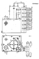
- the acting or control group mentioned comprises an electric motor (4), connected by means of the elastic coupling (11) to a hydraulic pump (12).
- This pump is included in a circuit having a fluid deposit (1), a safety valve (13) and an outlet to a series of electrovalves (9) numbered successively from 1 to n.
- the DC motor is controlled from the vehicle battery itself or from an auxiliary battery; on the axis of said engine, by means of a suitable transmission (11) there is incorporated the hydraulic pump (12), which in the physical representation of the figure (1) is included inside the deposit (I) which generally has a filling plug (3), a level observation hole (2) and a drain plug.
- the outlet of this pump (12) is connected to a pressure relief valve (13) which obviously creates a return path for the fluid from the deposit (1).
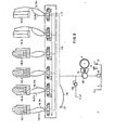
- the outlet from the hydraulic circuit of the pump (12) is made to several electro-valves (9) controlling the passage of the fluid towards the corresponding controlled element (18), regulated by the corresponding pulsator (20).
- the purpose of these solenoid valves is to act as a link between the programmed zone and the circuit execution zone, and in general it is a longitudinal distributor built with great precision. sion and controlled by an electromagnetic system like that shown in Figure 3, allowing the positioning of the slide at any point between the ends and the middle; this positioning of the slide is always proportional to the intensity of the electric excitation current of the coil and varies according to the sign thereof.
- the second fundamental group of this system consists of the corresponding command and control circuit thereof, which, in general, is located in a place of easy access for the user.
- This circuit is powered by the same battery as the motor (4) and is made according to a series of pairs of pulsators acting on each of the corresponding solenoid valves.
- the motor (4) is supplied to this battery by means of a contactor (7) controlled by pressing any of the elements of the keyboard (20).
- the entire circuit has the corresponding fuse and switch (19) at the input, which in a preferred embodiment is of the key type, possible to couple even on contact with the vehicle.
- Each pair of pulsators (20) has a first pulsator, activator of the motor (4) and consequently of the pump (12), which opens the corresponding solenoid valve in a determined direction and a second pulsator allowing the return of the fluid to the depot, which therefore allows the reverse function.
- the cylinder (18.5) controls a tilting device associated with the vehicle, if the latter is already provided with this self-tilting characteristic or if it is possible to introduce it.
- the cylinder (18.5) and the cylinder (18.6) can also be placed on both sides of the vehicle, so that by lifting it beforehand thanks to the front cylinders mentioned and by pressing the lateral cylinder on the ground you get lateral movement in any direction, pressing the vehicle only on the lifting cylinders.
- a pressure gauge (17) to collect the pressure supported by the hydraulic circuit. It is expected that said pressure gauge has a second corrective scale transforming the pressure into weight, which allows, by lifting the vehicle by means of the cylinders mentioned, to obtain on the scale a precise reference to the calibration of the vehicle.
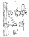
- FIG. 4 shows how to include in the chassis of the vehicle a U-shaped support (22) of a hydraulic cylinder (18) with a piston rod (23) at the end of which , using the bolt (25) is articulated a tab (24) provided at the end of a rolling element (27) controlled by a hydraulic motor (28).
- the end of this tab (24) has two projections (261) on which a beam (26) is articulated, the end of which is articulated with the support (22) by means of two bolts (262).
- the working position the vehicle is raised - large lines -.
- the rest position is indicated with cut lines.
- the damped tab (24) has hinge elements (244) in the upper part defining an internal cut where a spring (243) strikes.
- the liner of this tab (24) is welded to the cited hinge (244).
- Inside the jacket of this tab (24) is a rod (245) which also strikes the spring (243).
- the stroke of this rod (45) is limited by the pin (247) moving along an orifice which it has.
- the damping means provided for the tab (24), presented in FIG. 4 as having a mechanical character by means of the spring (243) can also be produced in a hydraulic system.
- the end of the rod (245) is associated with a U-shaped support (246) comprising in the ends of the wings and perpendicular to these wings, an axis (271) of the wheel (27) provided peripherally with a rim (272).
- a hydraulic motor (28) supported by a connecting piece (281) between the cited motor and the support (246) from the ends of the liner liner (24) there are two projections (248) on which by means of the screw (261) and by inserting the corresponding bearing are articulated laterally two side members (26) whose end is associated with the screws (262) to the support (22), also designed to be able to make an axial displacement.
- the length of the spar is equal to that of the lug plus that of the cylinder, i.e.
- the length of the spar is such that the extreme positions of the piston define their angular situations, for example the tab placed horizontally and vertically, the length of this spar being between two and three times the stroke of said rod.
- the length of the tab must be sufficient to allow the lifting of the vehicle and has a value of one or twice the length traveled by the cylinder rod.
- FIG. 5 in which there is a hydraulic diagram introducing a series of variants with respect to that in FIG. 2, this hydraulic diagram also starts from a fluid deposit (1), provided with a control hole (2), from which starts a fluid line which, through a suction filter (10) is set in motion by means of the pump (12) coupled to a motor, by means of an elastic coupling (11).
- a fluid deposit (1) provided with a control hole (2), from which starts a fluid line which, through a suction filter (10) is set in motion by means of the pump (12) coupled to a motor, by means of an elastic coupling (11).
- an electro-valve (9) the fluid exits through a line (1-5) which then branches off into two parallels (15.1) and (15.2) by means of a first flow divider (30).
- Each of these bifurcations in turn bifurcates into two others (15.1a) and (15.1b) by means of the dividers corresponding flow rates (31) and (32). In this way one obtains in the cylinders (18) the same stroke with
- the cited cylinders are protected with isolation valves or valves (33) and with limit switches (34) included in the body of the piston itself.
- the fluid return line (14) is made through a flow regulator.
- the outlet pipe has a branch (39), which by means of a circuit selector (36) allows the impulse of an auxiliary cylinder (18.5), generally arranged as a means of tilting the vehicle.
- hydraulic circuit has other accessory elements - safety valves (13) and return and air filter (38).
- the outlet line of the pump (12) has a branch (16) to a transducer (17), which measures the pressure and converts it into units of force.
- This device also includes a means of direct reading and printing, a watch, so that it can be used as an autonomous scale associated with the vehicle.
- These transducers relatively known on the current market have a tolerance of approximately 0.25 Z + very below a normal static rocker. For example, for a vehicle with a weight of 50 tonnes, the allowed tolerance is 125 kilos.
Landscapes
- Engineering & Computer Science (AREA)
- Mechanical Engineering (AREA)
- Vehicle Body Suspensions (AREA)
Priority Applications (1)
| Application Number | Priority Date | Filing Date | Title |
|---|---|---|---|
| EP86440044A EP0248967A1 (de) | 1986-06-06 | 1986-06-06 | Hydraulisches System |
Applications Claiming Priority (1)
| Application Number | Priority Date | Filing Date | Title |
|---|---|---|---|
| EP86440044A EP0248967A1 (de) | 1986-06-06 | 1986-06-06 | Hydraulisches System |
Publications (1)
| Publication Number | Publication Date |
|---|---|
| EP0248967A1 true EP0248967A1 (de) | 1987-12-16 |
Family
ID=8196421
Family Applications (1)
| Application Number | Title | Priority Date | Filing Date |
|---|---|---|---|
| EP86440044A Withdrawn EP0248967A1 (de) | 1986-06-06 | 1986-06-06 | Hydraulisches System |
Country Status (1)
| Country | Link |
|---|---|
| EP (1) | EP0248967A1 (de) |
Cited By (2)
| Publication number | Priority date | Publication date | Assignee | Title |
|---|---|---|---|---|
| FR2724617A1 (fr) * | 1994-09-19 | 1996-03-22 | Tencer Claude | Appareil permettant le levage puis le deplacement lateral de l'arriere d'un vehicule a 4 roues, muni de traction avant |
| CN103010069A (zh) * | 2011-09-22 | 2013-04-03 | 上海宝冶集团有限公司 | 用于吊斗车的电液控制系统 |
Citations (1)
| Publication number | Priority date | Publication date | Assignee | Title |
|---|---|---|---|---|
| EP0168050A2 (de) * | 1984-07-10 | 1986-01-15 | Hidrokar, S.A. | Hydraulisches System für Fahrzeuge |
-
1986
- 1986-06-06 EP EP86440044A patent/EP0248967A1/de not_active Withdrawn
Patent Citations (1)
| Publication number | Priority date | Publication date | Assignee | Title |
|---|---|---|---|---|
| EP0168050A2 (de) * | 1984-07-10 | 1986-01-15 | Hidrokar, S.A. | Hydraulisches System für Fahrzeuge |
Cited By (3)
| Publication number | Priority date | Publication date | Assignee | Title |
|---|---|---|---|---|
| FR2724617A1 (fr) * | 1994-09-19 | 1996-03-22 | Tencer Claude | Appareil permettant le levage puis le deplacement lateral de l'arriere d'un vehicule a 4 roues, muni de traction avant |
| CN103010069A (zh) * | 2011-09-22 | 2013-04-03 | 上海宝冶集团有限公司 | 用于吊斗车的电液控制系统 |
| CN103010069B (zh) * | 2011-09-22 | 2015-09-30 | 上海宝冶集团有限公司 | 用于吊斗车的电液控制系统 |
Similar Documents
| Publication | Publication Date | Title |
|---|---|---|
| CA1136917A (fr) | Attelage "trois points" utilisable aussi bien a l'avant qu'a l'arriere d'un vehicule industriel, agricole, pour travaux publics, ou forestier, par exemple un tracteur | |
| EP1644280B1 (de) | Aufzug | |
| EP0733584A1 (de) | Automatische Aufrichtvorrichtung für einen Kran mit zusammenklappbarem Ausleger | |
| WO2007000411A1 (fr) | Dispositif de direction à encombrement réduit pour atterrisseur d'aéronef | |
| EP0139561A1 (de) | Zu verschiedenen Stellungen bei Rückwärtsdrücken kippbarer Anhänger | |
| FR2507979A1 (fr) | Dispositif elevateur d'une plate-forme monte sur un vehicule automobile | |
| EP0479653B1 (de) | Montagevorrichtung für eine parallel zum Chassis eines Fahrzeuges ausfahrbare Ladebordwand | |
| EP0992415B1 (de) | Einrichtung zum Dämpfen der Querbewegung und des Schlingerns eines Fahrzeuges und mit einer solchen Vorrichtung ausgerüstetes Fahrzeug | |
| FR2856976A1 (fr) | Train d'atterrissage a jambes independantes du type a relevage vertical | |
| EP1018293A1 (de) | Mähmaschine | |
| EP0248967A1 (de) | Hydraulisches System | |
| EP0100926B1 (de) | Fahrzeug zur Handhabung von Materialien mit orientierbarem Ausleger und eingebautem Stabilisiergestell | |
| FR2718412A1 (fr) | Train d'atterrissage relevable pour avion gros porteur, du type à relevage vertical. | |
| FR2525581A1 (fr) | Dispositif de levage hydraulique pour le montage d'une fleche de grue | |
| EP0049193B1 (de) | Steuervorrichtung für eine klappbare und einziehbare hydraulische Hebebühne für Fahrzeuge | |
| FR2623151A3 (fr) | Dispositif hydraulique pour deplacer un vehicule automobile | |
| FR2577302A1 (fr) | Stabilisateur a inclinaison variable et semelle escamotable. | |
| FR2663590A1 (fr) | Engin de travaux publics ou similaires comportant un chassis articule en deux parties. | |
| FR2707947A1 (fr) | Train d'atterrissage d'aéronef, du type à relevage latéral. | |
| BE1004632A3 (fr) | Moissonneuse automotrice. | |
| FR2871654A1 (fr) | Ensemble de rampe pendulaire, et pulverisateur equipe d'un tel ensemble | |
| EP0561661B1 (de) | Kippvorrichtung für einen Behälter, der drehbar auf einem Fahrzeugrahmen montiert ist | |
| FR2686551A1 (fr) | Dispositif de blocage de suspension d'un vehicule. | |
| EP3705364A1 (de) | Stabilisator eines fahrzeugs | |
| CH373271A (fr) | Dispositif pour déplacer transversalement un véhicule automobile |
Legal Events
| Date | Code | Title | Description |
|---|---|---|---|
| PUAI | Public reference made under article 153(3) epc to a published international application that has entered the european phase |
Free format text: ORIGINAL CODE: 0009012 |
|
| STAA | Information on the status of an ep patent application or granted ep patent |
Free format text: STATUS: THE APPLICATION HAS BEEN WITHDRAWN |
|
| AK | Designated contracting states |
Kind code of ref document: A1 Designated state(s): AT BE CH DE FR GB IT LI LU NL SE |
|
| 18W | Application withdrawn |
Withdrawal date: 19871111 |