EP0248730B1 - Relatives Einstellungsverfahren von mehreren matrixförmigen Festkörpersensoren zur Kameraaustattung und Vorrichtung zum Durchführen dieses Verfahrens - Google Patents
Relatives Einstellungsverfahren von mehreren matrixförmigen Festkörpersensoren zur Kameraaustattung und Vorrichtung zum Durchführen dieses Verfahrens Download PDFInfo
- Publication number
- EP0248730B1 EP0248730B1 EP87401234A EP87401234A EP0248730B1 EP 0248730 B1 EP0248730 B1 EP 0248730B1 EP 87401234 A EP87401234 A EP 87401234A EP 87401234 A EP87401234 A EP 87401234A EP 0248730 B1 EP0248730 B1 EP 0248730B1
- Authority
- EP
- European Patent Office
- Prior art keywords
- regulation
- sensors
- sensor
- locking
- positioning
- Prior art date
- Legal status (The legal status is an assumption and is not a legal conclusion. Google has not performed a legal analysis and makes no representation as to the accuracy of the status listed.)
- Expired - Lifetime
Links
- 239000011159 matrix material Substances 0.000 title claims description 13
- 238000000034 method Methods 0.000 title claims description 9
- 238000012545 processing Methods 0.000 title description 2
- 230000003287 optical effect Effects 0.000 claims description 32
- 238000009432 framing Methods 0.000 claims description 20
- 238000013519 translation Methods 0.000 claims description 17
- 238000006073 displacement reaction Methods 0.000 claims description 9
- 239000000463 material Substances 0.000 claims description 5
- 230000001105 regulatory effect Effects 0.000 claims 3
- 230000014616 translation Effects 0.000 description 13
- 230000000903 blocking effect Effects 0.000 description 12
- 239000007787 solid Substances 0.000 description 8
- 238000003754 machining Methods 0.000 description 6
- 238000010586 diagram Methods 0.000 description 5
- 238000012360 testing method Methods 0.000 description 3
- PCTMTFRHKVHKIS-BMFZQQSSSA-N (1s,3r,4e,6e,8e,10e,12e,14e,16e,18s,19r,20r,21s,25r,27r,30r,31r,33s,35r,37s,38r)-3-[(2r,3s,4s,5s,6r)-4-amino-3,5-dihydroxy-6-methyloxan-2-yl]oxy-19,25,27,30,31,33,35,37-octahydroxy-18,20,21-trimethyl-23-oxo-22,39-dioxabicyclo[33.3.1]nonatriaconta-4,6,8,10 Chemical compound C1C=C2C[C@@H](OS(O)(=O)=O)CC[C@]2(C)[C@@H]2[C@@H]1[C@@H]1CC[C@H]([C@H](C)CCCC(C)C)[C@@]1(C)CC2.O[C@H]1[C@@H](N)[C@H](O)[C@@H](C)O[C@H]1O[C@H]1/C=C/C=C/C=C/C=C/C=C/C=C/C=C/[C@H](C)[C@@H](O)[C@@H](C)[C@H](C)OC(=O)C[C@H](O)C[C@H](O)CC[C@@H](O)[C@H](O)C[C@H](O)C[C@](O)(C[C@H](O)[C@H]2C(O)=O)O[C@H]2C1 PCTMTFRHKVHKIS-BMFZQQSSSA-N 0.000 description 2
- 238000001514 detection method Methods 0.000 description 2
- 238000011161 development Methods 0.000 description 2
- 230000018109 developmental process Effects 0.000 description 2
- 230000000694 effects Effects 0.000 description 2
- RTAQQCXQSZGOHL-UHFFFAOYSA-N Titanium Chemical compound [Ti] RTAQQCXQSZGOHL-UHFFFAOYSA-N 0.000 description 1
- 238000004026 adhesive bonding Methods 0.000 description 1
- 230000003831 deregulation Effects 0.000 description 1
- 239000011521 glass Substances 0.000 description 1
- 230000012447 hatching Effects 0.000 description 1
- 238000012986 modification Methods 0.000 description 1
- 230000004048 modification Effects 0.000 description 1
- 238000003825 pressing Methods 0.000 description 1
- 229910052719 titanium Inorganic materials 0.000 description 1
- 239000010936 titanium Substances 0.000 description 1
- 238000012546 transfer Methods 0.000 description 1
Images


Classifications
-
- H—ELECTRICITY
- H04—ELECTRIC COMMUNICATION TECHNIQUE
- H04N—PICTORIAL COMMUNICATION, e.g. TELEVISION
- H04N23/00—Cameras or camera modules comprising electronic image sensors; Control thereof
- H04N23/50—Constructional details
- H04N23/54—Mounting of pick-up tubes, electronic image sensors, deviation or focusing coils
Definitions
- the present invention relates to a system for positioning several solid matrix sensors fitted to a camera, in order to ensure a determined coincidence of the detected images.
- Solid matrix sensors are made up of charge transfer devices (generally CCD circuits, abbreviation of English terminology Charge Coupled Device).
- CCD circuits abbreviation of English terminology Charge Coupled Device
- the camera has at least two, generally three, matrix sensors.
- This equipment presents a problem which is the superposition of images and which can only be resolved by very precise and reliable positioning of the solid sensors.
- superimposition is meant either the exact coincidence pixel by pixel, or a determined relative coincidence, for example, an offset corresponding to the step of half a pixel in the case of interline matrices.
- Spacing matrices are used to increase the resolution of the image by doubling the number of points using two matrices.
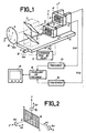
- the relative positioning of the sensors to ensure the desired coincidence presents multiple difficulties. Indeed, it must be considered in referring to FIG. 2 that there are altogether six adjustments per sensor, three are translations AX, AY, AZ along the axes X, Y, Z, Z being the optical axis and XY the conventional axes of the photosensitive plane of the sensor, the X direction corresponding to the direction lines.
- the other three settings are the rotations RX, RY around X, Y and RZ around the optical axis.
- the tilt settings correspond to the rotations RX and RY around X and Y which make it possible to bring the photosensitive plane ABCD orthogonal to the direction of the optical axis Z which ends at the detector.
- Two other so-called framing adjustments make it possible to carry out the displacements AY and AY so as to make the trace O of the optical axis Z substantially coincide with the center of the sensor corresponding to the center of the rectangular detection area ABCD.
- the adjustment by rotation RZ around the optical axis Z makes it possible to orient the image in a desired manner and the adjustment by translation AZ along this axis makes it possible to focus the image on the detector plane. (Such positioning is described in application EP-A-0231382 published on 12.08.87).
- the object of the invention is to remedy the aforementioned drawbacks by allowing the mechanical positioning of two or three solid matrix sensors behind a receiving optical system, with great precision and great stability.
- translations can be limited, within a range of the order of a millimeter and rotations of the order of a milliradiant, with positioning accuracy of the order of a micron.
- the proposed solution makes it possible to remedy the two essential factors of instability which must be taken into account: deregulation when the adjustments are immobilized and the adjustment by the effect of thermal expansions and mechanical vibrations.
- An object of the invention is to reduce the number of adjustments associated with each of the sensors; apart from the tilt settings common to all the sensors, these settings are reduced to two per sensor in the case of a pair of sensors.
- the additional settings to those of inclination are two for one of the sensors and three for each of the other two sensors. The choice of settings is made so as to lock the parts by mechanical clamping without causing any adjustment of the positions already carried out.
- FIG. 1 recalls the essential means presented by a camera with solid sensors.
- the camera comprises only two matrix sensors 1 and 2. These sensors are arranged on the optical output paths of an optical path separator device 3 which is itself placed downstream of a receiving optical objective 4.
- the separator 3 and the sensors 1 and 2 are mechanically mounted on a support part 5, each of the sensors being coupled to positioning means 11 and 12 which include the corresponding adjustments and blockings.
- the support part 5 is movable relative to the optical objective 4 in a direction parallel to that of the optical input axis Z.
- the corresponding means are symbolized by a guide element such as a slide 6 along which can slide a sole of the support element 5.
- the slide 6 is integral with the frame 10 constituting the envelope of the camera and which is symbolized by hatching).
- Circuit 9 represents the focusing command which allows this relative mechanical displacement indicated MZ. It is understood that the mechanical control can be exerted both on the support 5 and on the objective if the latter is equipped with a focusing control according to known techniques.
- Circuit 16 represents a routing circuit to select the first or second channel, and a mixer circuit to mix the two video channels.
- the circuits 13, 14 can be, if not wholly at least in part, included in the camera with the conventional circuits for reading the matrix and for video preamplification.
- the circuits 16 can be included in the monitor 15, in particular the mixer circuit for viewing a color image.
- the positioning means 11 and 12 which are mechanically coupled to the sensors 1 and 2 respectively each include the tilt settings corresponding to the rotations RX and RY to be performed around the two axes X and Y (See Fig. 2). These adjustments are made in the first place so as to make the sensitive surface A, B, C, D of the sensor perpendicular to the optical axis Z which reaches the latter. It then remains to carry out the framing adjustments by translation AX and AY along the X and Y axes, the adjustment of focus harmonization AZ by translation along the optical axis Z and the orientation adjustment by rotation RZ around the optical axis Z.
- the last four aforementioned settings are distributed over the two detection channels, each of the sensors 1 and 2 comprising only a pair of these settings.
- FIG. 3 shows in more detail a corresponding embodiment.
- the adjustment means associated with the sensor 1 comprise, in addition to the tilt adjustments RZ and RY, a first adjustment couple, the pair of framing adjustments AX and AY, while the adjustments associated with the sensor 2 additionally include adjustments of d tilt RX and RY, that of harmonization of focus AZ and that of image orientation RZ,
- the parts representing the positioning means are parallelepiped-shaped plates which may include machining operations, such as grooves and slides for carrying out the respective translations, and thus also an axis and a hollowed out part for carrying out the rotation about the axis. Z, without counting the other machining operations suitable for the passage of screwing elements for example.
- the sensor, 1 for example, is mounted by gluing or screwing on a parallelepipedal support plate 21, this plate 21 being followed by a second plate 22.
- the tilt movements to be carried out are fairly small, in practice from 1 to 2 / 10th of a millimeter.
- a possible solution comprises, as shown, a fixed point by means of a ball 23 which is housed in a spherical part 24 machined in the plate 22 and two mobile adjustment points constituted by the ends of the screws 25 and 26 which open out after screwing into the part 22 outside thereof and come to bear on the rear of the part 21 supporting the sensor.
- the plate 21 thus comprises three support points constituted by the ends of the screws 25 and 26 and by the ball 24.
- the operation of the screws 25 and 26 causes among other things the desired rotations RX and RY making it possible to position the plane of the sensor 1 perpendicular to its optical axis Z.
- a central locking screw 27 allows blocking in the direction of the Z axis by passing through a bore of the part 22 and by screwing on the part 21.
- To perform the tilt adjustment on can proceed, in a known manner, to a collimation consisting in forming an infinite image of a light test pattern and adjusting RX and RY to effect the coincidence of this test pattern with the image of this test pattern reflected by the surface of the sensor.
- the image of the target is advantageously a cross in a circle.
- the tilt adjustment for the second sensor 2 is identical, indicated by the homologous parts 31 to 37.
- the machining of the parts is determined so that the screw 27 passes freely through the part 22 and is screwed into the part 21 where its end cannot reach the sensor 1 It is the same for the part 37 through the part 32 to block the part 31 which supports the sensor 2.
- the other positioning and adjustment elements coupled to the sensor 1 include the following plates 28 and 29.
- the assembly formed by the sensor 1, its support 21 and the plate 22 is held by the screw 27.
- This assembly is moved by translation AX in the direction X of the sensor with a clearance which remains in a range of the order of a millimeter for example.
- the displacement is made possible by a slide 28A of the part 28 which cooperates with a groove 22A machined in the part 22.
- the displacement by translation AY along the Y axis with an amplitude also maximum of the order of a millimeter is provided by a slide 29A of the plate 29 placed in front of the groove 28B of the part 28.
- the part 29 is applied by its rear face to the support part 5.
- Screws 30-1 are screwed into the part 22 after crossing parts 29 and 28 in order to block the assembly 29, 28, 22, 21 and 1 on the support 5, the blocking direction being the direction of the optical axis Z perpendicular to X and Y and therefore perpendicular to the two adjustment directions.
- the holes for the passage of the corresponding screws 30-1 in the parts 29, 28 are bored to a diameter greater than that of the screws so as to take account of the maximum range of travel of the translations AX and AY.
- the screws 30-1 can be 4 in number arranged two by two laterally as shown.
- the loosening of the four screws 30-1 is carried out in a limited way to leave a hard with a certain coefficient of friction which keeps this assembly immobile after the desired AY translation and then authorizes the locking of the screws 30-1 without the Y position having changed.
- the friction can be easily obtained by using, for example, plastic material washers between the screw heads 30-1 and the support 5.
- the part 32 has a cylindrical part 32A which fits into a cylindrical housing 39A of the part 39.
- the cylindrical housing is extended by lateral slots 39B and 39C which confer a certain elasticity and greater precision during blocking by the screws 38.
- These coplanar machining operations according to a diameter of the cylinder make it possible to maintain in position the optical axis when tightening the screws 38.
- a set of four screws 30-2 make integral with the support 5 the part 39 which has corresponding tapped holes.
- FIG. 4 represents an alternative embodiment of the part 39 according to which the slots 39B and 39C are extended at the end by terminal cylindrical parts 39D and 39E respectively, and also oriented in the direction of the optical axis Z.
- the machining of these recesses is carried out so as to respect the symmetry with equal thicknesses of material on either side represented by the distances D1 and D2.
- the harmonization of development of the second channel is obtained by moving by translation AZ along the optical axis Z all of the parts 2, 31 and 32, this assembly being blocked by the screw 37 after the preliminary adjustment d 'tilt. Focusing can be controlled with monitor 15, ensuring the sharpness of the video image of this channel.
- the assembly 2, 31 and 32 is then rotated around the Z axis to carry out the desired RZ orientation adjustment.
- the aim of this adjustment is to bring the direction X of the second sensor to coincide with that X of the first sensor which constitutes the orientation reference.
- the orientation adjustment is minimal, its stroke is generally less than 1 milliradiant; it is performed by action in a plane perpendicular to Z and therefore has no influence on the previous AZ focus adjustment.
- the two video channels are displayed simultaneously on the monitor 15.
- the AZ and RZ adjustments are then blocked by the two screws 38 in a direction perpendicular to the Z axis, the screws 38 having for example the direction Y indicated in the XY plane.
- the screws 38 act by pressing on the part 39, producing an approximation of the surfaces of the slots 39A and 39C.
- the means 21, 22, 28 and 29 associated with the first sensor 1 are the same as those used previously to perform the framing in X and in Y.
- the positioning means which are associated with the two other sensors 2 and 7 comprise, for the second channel, the parts already indicated 31, 32 and 39 with a modification on the latter to further allow framing adjustment by translation in Y.
- the third track includes a set of similar pieces numbered 41, 42 and 49, the piece 49 also being arranged to allow framing adjustment but this time in the orthogonal direction X.
- the immobilization of the settings of the second and third sensors poses a problem, the settings in X and in Y being blocked on the Z axis which itself has settings.
- This immobilization is carried out by blocking in Z of the parts 39 and 49 by means of the corresponding screws 30-2 and 30-7; this blocking does not immobilize the AZ and RZ settings which can then be carried out on these channels and be finally blocked using parts 38 and 48.
- the third sensor 7 imposes the Y axis, the second sensor 2 imposes the X axis and the first sensor 1 imposes the orientation reference angle.
- the order of the settings is broken down as follows. First of all, the tilt settings corresponding to the rotations RX and RY already mentioned are carried out.
- the remaining adjustments comprise a first series relating to the framing adjustments in X and in Y on the channel of the sensor 1, in Y on the channel of the second sensor 2, and in X on the channel the third sensor 7.
- These framing adjustments are made in a certain order; first of all, the centers of the third sensor 7 and of the second sensor 2 coincide, which comprise the setting AX and the setting AY respectively.
- the end piece 39 and 49 comprises, for example, a groove 39A and 49A respectively
- the support 5 comprises a slide respectively 5A and 5B opposite the groove for guiding in the direction Y or X corresponding.
- the image focusing by displacement MZ between the optics 4 and the support 5 is carried out on the first channel which no longer has any adjustment, since this first channel is mechanically blocked on the support 5 .
- the support 5 as well as the positioning parts can advantageously be made of a material such as titanium which has a coefficient of expansion close to that of the glasses used to make the receiving optics 4.
Landscapes
- Engineering & Computer Science (AREA)
- Multimedia (AREA)
- Signal Processing (AREA)
- Mounting And Adjusting Of Optical Elements (AREA)
Claims (7)
- Verfahren zur relativen Positionierung einer Mehrzahl von zur Ausrüstung einer Kamera gehörigen matrixartigen Festkörper-Meßwertaufnehmern, mit dem eine bestimmte Koinzidenz der von diesen Meßwertaufnehmern erfaßten Bilder gewährleistet wird, wobei die Meßwertaufnehmer in den optischen Wegen der Ausgabe einer Lichtweg-Trenneinrichtung hinter dem Aufnahmeobjektiv der Kamera angeordnet sind, wobei die Trenneinrichtung und die Meßwertaufnehmer mechanisch verbunden auf einem Träger angebracht sind und wobei die Koinzidenz entlang der X- und Y-Achse der Erfassungsebene der Meßwertaufnehmer und entlang einer zu dieser Ebene senkrechten optischen Z-Achse aufgrund von Neigungseinstellungen durch die Drehung um die X- und Y-Achse für die Gewinnung einer zur optischen Z-Achse senkrechten Erfassungsebene, aufgrund von Ausschnittseinstellungen durch Translation in X- und Y- Richtung für die Positionierung eines Meßaufnehmerzentrums in dem der optischen Z-Achse entsprechenden Zentrum, aufgrund von Scharfabstimmungseinstellungen durch Translation entlang der optischen Z-Achse und aufgrund von Orientierungseinstellungen des Bildes durch Drehung um die optische Z-Achse bewerkstelligt wird, wobei das Verfahren dadurch gekennzeichnet ist, daß es im Falle zweier Meßwertaufnehmer (1, 2) nacheinander umfaßt:- Einstellen der Neigung der Erfassungsebene eines jeden der Meßwertaufnehmer (1, 2) und Sperren der entsprechenden Einstellungen;- Einstellen des Ausschnitts des ersten Meßwertaufnehmers (1) in X- und Y-Richtung und Sperren der entsprechenden Einstellungen entlang der Z-Achse mittels eines Sperrelementes (30-1);- scharfes Einstellen des Bildes auf den ersten Meßwertaufnehmer (1) durch die relative Verschiebung (MZ) der Optik (4) in bezug auf den Träger (5) der die Trenneinrichtung und die Meßwertaufnehmer umfassenden Gesamtheit;- Einstellen der Scharfabstimmung und der Orientierung des Bildes des zweiten Meßwertaufnehmers (2) und Sperren der entsprechenden Einstellungen in einer Richtung in der XY-Ebene.
- Positionierungseinrichtung für die Ausführung des Verfahrens gemäß Anspruch 1, mit Neigungseinstellungsmitteln, Ausschnittseinstellungsmitteln und Scharfabstimmungs- und Bildorientierungs-Einstellungsmitteln, wobei die Meßwertaufnehmer (1) und (2) mit ersten bzw. mit zweiten Positionierungsmitteln gekoppelt sind, wobei die Einrichtung dadurch gekennzeichnet ist, daß das erste Positionierungsmittel (11) Mittel für die Neigungseinstellung (21-27) und Mittel für Ausschnittseinstellungen (28, 29) in X- und Y-Richtung und für deren Sperrung in Z-Richtung (30-1) umfaßt, woraus eine Verbindung des ersten Meßwertaufnehmers (1) mit dem Träger (5) resultiert, und daß das zweite Positionierungsmittel (12) Mittel für die Neigungseinstellung (31-37) und Mittel für die Einstellungen der Scharfabstimmung und der Bildorientierung (32, 39) bei deren Sperrung in der XY-Ebene (38) umfaßt.
- Verfahren zur Positionierung gemäß Anspruch 1, dadurch gekennzeichnet, daß es im Falle dreier Meßwertaufnehmer (1, 2, 7) nacheinander umfaßt:- Einstellen der Neigung der Erfassungsebene eines jeden der Meßwertaufnehmer (1, 2, 7) und Sperren der entsprechenden Einstellungen;- Einstellen des Ausschnitts der drei Meßwertaufnehmer, indem zunächst die Koinzidenz zwischen den Zentren des zweiten Meßwertaufnehmers (2) und des dritten Meßwertaufnehmers (7) bei Immobilisierung in Y- bzw. in X- Richtung mittels eines Sperrelementes (30-2, 30-7), woraus eine Sperrung entlang der optischen Z-Achse und die Verbindung mit dem Träger (5) resultiert, und dann die Koinzidenz des Zentrums des ersten Meßwertaufnehmers (1) mit den Zentren der zwei anderen Meßwertaufnehmer (2 und 7), durch die Translation (AX und AY) in X- und Y-Richtung und die Sperrung dieser Einstellungen entlang der entsprechenden optischen Z-Richtung bewerkstelligt werden;- scharfes Abstimmen des Bildes auf den ersten Meßwertaufnehmer (1) durch die Verschiebung (MZ) der Optik (4) relativ zum Träger (5) der die Trenneinrichtung und die Meßwertaufnehmer umfassenden Gesamtheit;- Einstellen der Orientierung (RZ) des zweiten (2) und des dritten (7) Meßwertaufnehmers in bezug auf den als Bezugspunkt genommenen ersten Meßwertaufnehmer und Scharfabstimmungseinstellung (AZ) dieser zwei Meßwertaufnehmer durch die Translation entlang der jeweiligen optischen Z-Achse und anschließendes jeweiliges Sperren dieser zwei Einstellungen entlang einer Richtung in der XY-Ebene, die jedem der Wege entspricht.
- Positionierungseinrichtung für die Ausführung des Verfahrens gemäß Anspruch 3, mit Neigungseinstellungsmitteln, Ausschnittseinstellungsmitteln und Scharfabstimmungs- und Bildorientierungseinstellungsmitteln, wobei die Meßwertaufnehmer (1), (2) und (7) mit ersten bzw. zweiten bzw. dritten Positionierungsmitteln gekoppelt sind, wobei die Einrichtung dadurch gekennzeichnet ist, daß das erste Positionierungsmittel Mittel für die Einstellungen der Neigung (21-27) und Mittel für die Einstellungen des Ausschnitts (28, 29) umfaßt, daß das zweite Positionierungsmittel Mittel für die Einstellungen der Neigung (31-37), Mittel für die Einstellungen der Scharfabstimmung und der Bildorientierung (32, 39) und Mittel (39A, 5A) für die Einstellung des Ausschnitts entweder entlang der X- oder entlang der Y- Richtung umfaßt und daß das dritte Postionierungsmittel Mittel für die Einstellung der Neigung (41-47), Mittel für die Einstellungen der Scharfabstimmung und der Bildorientierung (42-49) und Mittel (49A, 5B) für eine Einstellung des Ausschnitts entlang der jeweils anderen der X- oder Y- Richtungen umfaßt.
- Einrichtung gemäß einem der Ansprüche 2 und 4, dadurch gekennzeichnet, daß für die Ausführung der Scharfabstimmung (AZ) und der Bildorientierung (RZ) die entsprechenden Positionierungsmittel zwei Stücke aufweisen, von denen eines (32, 42) einen zylindrischen Teil (32A) und das andere (39, 49) eine entsprechende zylindrische Aussparung (39A) besitzt, wobei diese zylindrische Aussparung durch zu einem Durchmesser des Zylinders koplanare seitliche Schlitze (39B, 39C) erweitert wird, die dem Stück bei der Sperrung eine bestimmte Elastizität verleihen, wobei die ausgesparten Teile im Körper des Stückes symmetrisch verteilt sind, um einerseits in X-Richtung und andererseits in Y-Richtung die gleichen Materialdicken (D1, D2) zu ergeben, derart, daß die Zentrierung (G) auf der entsprechenden Z-Achse erhalten bleibt.
- Einrichtung gemäß einem der Ansprüche 2, 4 und 5, dadurch gekennzeichnet, daß die Positionierungsmittel des dem Meßwertaufnehmer (1) entsprechenden ersten Weges versehen sind mit einer ersten Platte (21), auf der der Meßwertaufnehmer angebracht ist, einer zweiten Platte (22), die mit einer Einrichtung zur Dreipunkt-Neigungseinstellung mittels einer Kugel (23) und zwei Schrauben (25 und 26) versehen ist, wobei die zweite Platte eine Nut (22A) in X-Richtung aufweist, einem dritten Stück (28) mit einer Schiene (28A) gegenüber der Nut, wobei das dritte Stück außerdem eine Nut (28B) in Y-Richtung aufweist, und einem vierten Stück (29) mit einer Schiene (29A) in Y-Richtung gegenüber der Nut in Y-Richtung und Mitteln zum Sperren mittels Schrauben (27, 30-1) der Neigungs- und Ausschnittseinstellungen.
- Einrichtung gemäß Anspruch 6, dadurch gekennzeichnet, daß die Positionierungsmittel des dem zweiten Meßwertaufnehmer (2) entsprechenden Weges homolog versehen sind mit zwei ersten Platten (31 und 32) und der entsprechenden Neigungs- und Sperr-Einstelleinrichtung (37), wobei die zweite Platte (32) einen zylindrischen Teil aufweist und wobei eine mit dem Träger (5) verbundene dritte Platte (39) mit einer dem Zylinder entsprechenden gebohrten Aussparung (39A) versehen ist.
Applications Claiming Priority (2)
| Application Number | Priority Date | Filing Date | Title |
|---|---|---|---|
| FR8608221 | 1986-06-06 | ||
| FR8608221A FR2599921B1 (fr) | 1986-06-06 | 1986-06-06 | Systeme de positionnement relatif de plusieurs capteurs solides matriciels equipant une camera |
Publications (2)
| Publication Number | Publication Date |
|---|---|
| EP0248730A1 EP0248730A1 (de) | 1987-12-09 |
| EP0248730B1 true EP0248730B1 (de) | 1992-01-29 |
Family
ID=9336102
Family Applications (1)
| Application Number | Title | Priority Date | Filing Date |
|---|---|---|---|
| EP87401234A Expired - Lifetime EP0248730B1 (de) | 1986-06-06 | 1987-06-02 | Relatives Einstellungsverfahren von mehreren matrixförmigen Festkörpersensoren zur Kameraaustattung und Vorrichtung zum Durchführen dieses Verfahrens |
Country Status (3)
| Country | Link |
|---|---|
| EP (1) | EP0248730B1 (de) |
| DE (1) | DE3776410D1 (de) |
| FR (1) | FR2599921B1 (de) |
Families Citing this family (1)
| Publication number | Priority date | Publication date | Assignee | Title |
|---|---|---|---|---|
| ATE158129T1 (de) * | 1992-03-23 | 1997-09-15 | Canon Kk | Bildaufnahmevorrichtung mit mehreren linsen und korrektur von falschregistrierung |
Family Cites Families (3)
| Publication number | Priority date | Publication date | Assignee | Title |
|---|---|---|---|---|
| JPS58140156A (ja) * | 1982-02-16 | 1983-08-19 | Canon Inc | 固体撮像装置 |
| JPS58215874A (ja) * | 1982-06-09 | 1983-12-15 | Canon Inc | 固体撮像素子の取付け構造及び電子カメラ |
| JPH065717B2 (ja) * | 1983-03-04 | 1994-01-19 | 株式会社日立製作所 | 固 体 撮 像 装 置 |
-
1986
- 1986-06-06 FR FR8608221A patent/FR2599921B1/fr not_active Expired
-
1987
- 1987-06-02 DE DE8787401234T patent/DE3776410D1/de not_active Expired - Fee Related
- 1987-06-02 EP EP87401234A patent/EP0248730B1/de not_active Expired - Lifetime
Also Published As
| Publication number | Publication date |
|---|---|
| DE3776410D1 (de) | 1992-03-12 |
| FR2599921B1 (fr) | 1988-08-19 |
| EP0248730A1 (de) | 1987-12-09 |
| FR2599921A1 (fr) | 1987-12-11 |
Similar Documents
| Publication | Publication Date | Title |
|---|---|---|
| EP1098556B1 (de) | Einrichtung zur Bestimmung eines Positionsfehlers | |
| FR2744236A1 (fr) | Objectif zoom du type telescopique et mecanisme a came pour celui-ci | |
| CH340416A (fr) | Machine à composer photographique | |
| FR3070502A1 (fr) | Telescope a montage simplifie et procede de reglage d'un tel telescope | |
| EP0944845A1 (de) | Vorrichtung zur lokalisierung von strahlungsquellen | |
| EP0248730A1 (de) | Relatives Einstellungsverfahren von mehreren matrixförmigen Festkörpersensoren zur Kameraaustattung und Vorrichtung zum Durchführen dieses Verfahrens | |
| EP0768551A1 (de) | Optisches System zum Betrachten breiter Blickfelder | |
| US7289199B2 (en) | Electronic imaging apparatus and microscope apparatus using the same | |
| FR2569016A1 (fr) | Dispositif pour l'harmonisation des axes optiques d'un viseur | |
| EP0968450A1 (de) | Mikrometrische positionierungsvorrichtung einer halterung eines optischen elements mit sechs freiheitsgraden | |
| US5042913A (en) | Electrical signal forming apparatus having image splitting prism | |
| FR2548384A1 (fr) | Dispositif a imagerie video, notamment pour autodirecteur | |
| EP0611454A1 (de) | Vorrichtung für Mikroabtastung und Infrarotkamera ausgestattet mit einer solchen Vorrichtung | |
| Brubaker et al. | Optomechanics of a free-space photonic switch: the components | |
| EP3818391B1 (de) | Optronische sicht und zugehörige plattform | |
| WO2022129770A2 (fr) | Systeme optique imageur a trois miroirs | |
| FR2602623A1 (fr) | Systeme de blocage par scellement du positionnement relatif des capteurs dtc matriciels equipant une camera | |
| WO2006069886A1 (fr) | Capteur d'image a zones de couleur globalement separees | |
| EP0221606B1 (de) | Optisches Aufnahme- oder Projektionsgerät | |
| EP1795937B1 (de) | Sphärischer Feldwechsler | |
| FR2627042A1 (fr) | Dispositif de prise de vue d'images fixes de haute definition | |
| JPH01295701A (ja) | レンズ円筒枠心出し旋削装置 | |
| EP4391568A1 (de) | Elektronische halterung für bildaufnahmevorrichtung, anordnung mit einer solchen halterung und bildaufnahmevorrichtung mit einer solchen anordnung | |
| FR2723269A1 (fr) | Procede de reglage d'alignement et de focalisation d'un laser de puissance a voie multiple et dispositif de mise en oeuvre | |
| JP2789124B2 (ja) | 光アイソレータ |
Legal Events
| Date | Code | Title | Description |
|---|---|---|---|
| PUAI | Public reference made under article 153(3) epc to a published international application that has entered the european phase |
Free format text: ORIGINAL CODE: 0009012 |
|
| AK | Designated contracting states |
Kind code of ref document: A1 Designated state(s): DE GB IT |
|
| 17P | Request for examination filed |
Effective date: 19880416 |
|
| RAP3 | Party data changed (applicant data changed or rights of an application transferred) |
Owner name: THOMSON-CSF |
|
| 17Q | First examination report despatched |
Effective date: 19900814 |
|
| GRAA | (expected) grant |
Free format text: ORIGINAL CODE: 0009210 |
|
| AK | Designated contracting states |
Kind code of ref document: B1 Designated state(s): DE GB IT |
|
| ITF | It: translation for a ep patent filed | ||
| REF | Corresponds to: |
Ref document number: 3776410 Country of ref document: DE Date of ref document: 19920312 |
|
| GBT | Gb: translation of ep patent filed (gb section 77(6)(a)/1977) | ||
| ITTA | It: last paid annual fee | ||
| PLBE | No opposition filed within time limit |
Free format text: ORIGINAL CODE: 0009261 |
|
| STAA | Information on the status of an ep patent application or granted ep patent |
Free format text: STATUS: NO OPPOSITION FILED WITHIN TIME LIMIT |
|
| 26N | No opposition filed | ||
| REG | Reference to a national code |
Ref country code: GB Ref legal event code: 746 Effective date: 19940325 |
|
| PGFP | Annual fee paid to national office [announced via postgrant information from national office to epo] |
Ref country code: GB Payment date: 19960516 Year of fee payment: 10 |
|
| PGFP | Annual fee paid to national office [announced via postgrant information from national office to epo] |
Ref country code: DE Payment date: 19960517 Year of fee payment: 10 |
|
| PG25 | Lapsed in a contracting state [announced via postgrant information from national office to epo] |
Ref country code: GB Effective date: 19970602 |
|
| GBPC | Gb: european patent ceased through non-payment of renewal fee |
Effective date: 19970602 |
|
| PG25 | Lapsed in a contracting state [announced via postgrant information from national office to epo] |
Ref country code: DE Free format text: LAPSE BECAUSE OF NON-PAYMENT OF DUE FEES Effective date: 19980303 |
|
| PG25 | Lapsed in a contracting state [announced via postgrant information from national office to epo] |
Ref country code: IT Free format text: LAPSE BECAUSE OF NON-PAYMENT OF DUE FEES;WARNING: LAPSES OF ITALIAN PATENTS WITH EFFECTIVE DATE BEFORE 2007 MAY HAVE OCCURRED AT ANY TIME BEFORE 2007. THE CORRECT EFFECTIVE DATE MAY BE DIFFERENT FROM THE ONE RECORDED. Effective date: 20050602 |