EP0248726B1 - Vorrichtung zur axialen Einspannung eines torusförmigen Fusionsapparates - Google Patents
Vorrichtung zur axialen Einspannung eines torusförmigen Fusionsapparates Download PDFInfo
- Publication number
- EP0248726B1 EP0248726B1 EP87401229A EP87401229A EP0248726B1 EP 0248726 B1 EP0248726 B1 EP 0248726B1 EP 87401229 A EP87401229 A EP 87401229A EP 87401229 A EP87401229 A EP 87401229A EP 0248726 B1 EP0248726 B1 EP 0248726B1
- Authority
- EP
- European Patent Office
- Prior art keywords
- enclosure
- concrete
- installation according
- installation
- support structure
- Prior art date
- Legal status (The legal status is an assumption and is not a legal conclusion. Google has not performed a legal analysis and makes no representation as to the accuracy of the status listed.)
- Expired - Lifetime
Links
Images


Classifications
-
- G—PHYSICS
- G21—NUCLEAR PHYSICS; NUCLEAR ENGINEERING
- G21B—FUSION REACTORS
- G21B1/00—Thermonuclear fusion reactors
- G21B1/11—Details
-
- Y—GENERAL TAGGING OF NEW TECHNOLOGICAL DEVELOPMENTS; GENERAL TAGGING OF CROSS-SECTIONAL TECHNOLOGIES SPANNING OVER SEVERAL SECTIONS OF THE IPC; TECHNICAL SUBJECTS COVERED BY FORMER USPC CROSS-REFERENCE ART COLLECTIONS [XRACs] AND DIGESTS
- Y02—TECHNOLOGIES OR APPLICATIONS FOR MITIGATION OR ADAPTATION AGAINST CLIMATE CHANGE
- Y02E—REDUCTION OF GREENHOUSE GAS [GHG] EMISSIONS, RELATED TO ENERGY GENERATION, TRANSMISSION OR DISTRIBUTION
- Y02E30/00—Energy generation of nuclear origin
- Y02E30/10—Nuclear fusion reactors
Definitions
- the present invention relates to an axial clamping system of the toric reactor of a nuclear fusion installation.
- the axial clamping device consisting of the tie rod and the associated cylinders is therefore expensive and undesirable in a place where numerous equipment such as the electrical winding, the cooling circuits and the measuring devices must be installed, and where the layout constraints are therefore serious.
- the present invention relates to an axial clamping device of a toroidal melting device which consists in making the forces brought into play by the external biological protection enclosure take up again.
- This axial clamping device comprises a toroidal-shaped reactor inside which the fusion takes place, a support structure for said toroid with a generally cylindrical outline ensuring the reactor double axial and radial clamping and an external enclosure for biological protection, and is characterized by the fact that the axial clamping forces transmitted to the torus via the support structure are taken up by the external concrete enclosure by means of jacks, the central tie being eliminated.
- the device object of the invention also allows the use of cylinders having a conventional active fluid, liquid at room temperature.
- the nuclear fusion installation represented in FIG. 1 comprises an external enclosure 1 of biological protection made of concrete, hermetic except for the passage sectors 2 of the power supply cables and the fluid pipeline, of access doors 3 and of handling hoppers 4, these various openings being closed when the installation is put into service.
- This enclosure 1 contains the melting device 11 consisting inter alia of a support structure 5 and a torus 8, held by the support structure 5, where the fusion takes place.
- the support structure 5 is held by circumferential hooping hoops 6 which may be made up of cables ensuring a prestress; it is placed on the floor 12 of the enclosure 1 by means of pillars 7 and tightened axially by means of a central tie rod which passes right through it and which carries two shoulders 13 and 14 at its upper ends and lower. It is on one of these shoulders that the clamping cylinders are placed 10.
- the tie rod 9 therefore undergoes a tensile force equal to the compressive force undergone by the support structure 5.
- the cylinders 10 are placed at inside the cryostat 35 filled with liquefied gas, their operating temperature is very low, which requires the use of a cryogenic active fluid to guarantee proper operation of the latter.
- FIG. 2 again shows a fusion toroid 8, a support structure 5 held radially by hoops 6 and an enclosure 1 of biological protection provided with the same openings 2, 3, 4 as in Figure 1.
- the axial clamping of the melting device 11 is precisely ensured by this enclosure 1, the upper and lower walls of which are thickened in their center and inwards, so as to form abutments 18 on which there are supports 7 and cylinders 16.
- the enclosure 1 which has become working must be the subject of a more elaborate construction than in the prior art of FIG. 1, the concrete having mechanical properties of traction and shear much lower than those of compression.
- the enclosure 1 is made of reinforced concrete.
- the enclosure 1 can consist of resistant metal frames embedded in the concrete and playing the role of reinforcement.
- the concrete is prestressed by vertical cables 19 arranged in the side wall of the enclosure 1 and by cables 20 diametrically arranged in its upper and lower walls.
- the stops 18 allow a better distribution of the stresses.
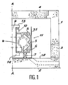
- FIG. 3 Another embodiment of the invention is shown in Figure 3.
- the axial clamping force is transmitted from the cylinders 16 to the enclosure 1 by means of a metal frame 27 which can be linked to said enclosure 1 by removable wedges 28 and support structures 29.
- the side wall of the enclosure 1 is curved inwards at its upper 36 and lower 34 ends in the form of a keg.
- the lower wall 32 of the enclosure 1 is frustoconical, which generates a lower space 33 which can receive a room containing for example diagnostic means and a lateral space 31, also limited by the oblique lower end 34 of the enclosure 1 and by a service floor 30.
- This space 31 can advantageously be occupied by power supplies and fluid pipes, freeing up the space above the floor 30 for the benefit of maintenance robots.
- the vertical cables 19 follow the curvature of the side wall, and the installation is completed by networks of circumferential prestressing cables 25. It is then possible to make removable part of the upper wall of the enclosure 1 not in contact with the wedges 28 to make a hatch 26 through which we can pass the fusion device 11 previously assembled outside.
Landscapes
- Physics & Mathematics (AREA)
- Engineering & Computer Science (AREA)
- Plasma & Fusion (AREA)
- General Engineering & Computer Science (AREA)
- High Energy & Nuclear Physics (AREA)
- Structure Of Emergency Protection For Nuclear Reactors (AREA)
- Graft Or Block Polymers (AREA)
- Crystals, And After-Treatments Of Crystals (AREA)
- Peptides Or Proteins (AREA)
- Physical Or Chemical Processes And Apparatus (AREA)
- Load-Engaging Elements For Cranes (AREA)
- Containers, Films, And Cooling For Superconductive Devices (AREA)
Claims (6)
Applications Claiming Priority (2)
| Application Number | Priority Date | Filing Date | Title |
|---|---|---|---|
| FR8607971 | 1986-06-03 | ||
| FR8607971A FR2599540B1 (fr) | 1986-06-03 | 1986-06-03 | Dispositif de serrage axial d'un appareil torique de fusion |
Publications (2)
| Publication Number | Publication Date |
|---|---|
| EP0248726A1 EP0248726A1 (de) | 1987-12-09 |
| EP0248726B1 true EP0248726B1 (de) | 1990-10-10 |
Family
ID=9335943
Family Applications (1)
| Application Number | Title | Priority Date | Filing Date |
|---|---|---|---|
| EP87401229A Expired - Lifetime EP0248726B1 (de) | 1986-06-03 | 1987-06-02 | Vorrichtung zur axialen Einspannung eines torusförmigen Fusionsapparates |
Country Status (5)
| Country | Link |
|---|---|
| EP (1) | EP0248726B1 (de) |
| JP (1) | JPS62293183A (de) |
| DE (2) | DE3765465D1 (de) |
| ES (1) | ES2001002B3 (de) |
| FR (1) | FR2599540B1 (de) |
Families Citing this family (1)
| Publication number | Priority date | Publication date | Assignee | Title |
|---|---|---|---|---|
| US6344739B1 (en) | 1999-02-12 | 2002-02-05 | R/D Tech Inc. | Eddy current probe with multi-use coils and compact configuration |
Family Cites Families (2)
| Publication number | Priority date | Publication date | Assignee | Title |
|---|---|---|---|---|
| FR2262378B1 (de) * | 1974-02-26 | 1976-12-03 | Commissariat Energie Atomique | |
| DE2725439A1 (de) * | 1977-06-04 | 1978-12-14 | Hochtemperatur Reaktorbau Gmbh | Zylindrischer spannbetondruckbehaelter fuer ein kernkraftwerk grosser leistungen |
-
1986
- 1986-06-03 FR FR8607971A patent/FR2599540B1/fr not_active Expired
-
1987
- 1987-06-02 JP JP62138842A patent/JPS62293183A/ja active Pending
- 1987-06-02 DE DE8787401229T patent/DE3765465D1/de not_active Expired - Lifetime
- 1987-06-02 EP EP87401229A patent/EP0248726B1/de not_active Expired - Lifetime
- 1987-06-02 ES ES87401229T patent/ES2001002B3/es not_active Expired - Lifetime
- 1987-06-02 DE DE198787401229T patent/DE248726T1/de active Pending
Also Published As
| Publication number | Publication date |
|---|---|
| ES2001002B3 (es) | 1992-01-01 |
| EP0248726A1 (de) | 1987-12-09 |
| DE3765465D1 (de) | 1990-11-15 |
| FR2599540B1 (fr) | 1988-07-29 |
| ES2001002A4 (es) | 1988-04-16 |
| FR2599540A1 (fr) | 1987-12-04 |
| DE248726T1 (de) | 1988-06-09 |
| JPS62293183A (ja) | 1987-12-19 |
Similar Documents
| Publication | Publication Date | Title |
|---|---|---|
| EP0161978B1 (de) | Schwingungsdämpfungsvorrichtung für die Befestigung eines Rohres dessen Wandstärke klein ist im Verhältnis zum Durchmesser | |
| US8923939B2 (en) | Superconduction apparatus | |
| US20050286674A1 (en) | Composite-wall radiation-shielded cask and method of assembly | |
| EP0248726B1 (de) | Vorrichtung zur axialen Einspannung eines torusförmigen Fusionsapparates | |
| US4482878A (en) | Integrated conductor and coil structure for superconducting coils | |
| EP0049197B1 (de) | Wärmedämmvorrichtung zum Isolieren des oberen Bereichs eines zwischen dem Hauptbehälter und dem Sicherheitsbehälter eines Kernreaktors liegenden Ringraumes | |
| US5301507A (en) | Superconducting magnetic energy storage device | |
| Wang et al. | Fabrication experiences of the coal-fired flow facility superconducting dipole magnet | |
| EP0092461B1 (de) | Behälter mit ringförmiger Deckelplatte für einen schnellen Kernreaktor | |
| JP2765044B2 (ja) | 極低温部材の支持構造 | |
| JP4114766B2 (ja) | 極低温リードスルー | |
| Hagedorn et al. | Design and construction of a twin-aperture prototype magnet for the CERN LHC project | |
| FR2559568A1 (fr) | Dispositif de refroidissement du fourreau de la tige de commande d'un robinet a joint gele | |
| JPH0194605A (ja) | 超電導コイルの冷凍容器 | |
| Inagaki et al. | Large aperture superconducting magnet (Benkei) | |
| Wang et al. | A superconducting dipole magnet for the UTSI MHD facility | |
| Wang et al. | Final design of a superconducting MHD magnet for the coal-fired flow facility at the University of Tennessee Space Institute | |
| Losasso et al. | Design and status of construction of Finuda superconducting aluminium stabilised detector | |
| Niemann et al. | Cryogenic aspects of the US SCMS superconducting dipole magnet for MHD research | |
| Kim et al. | Performance test of the KSTAR Central Solenoid (CS) model coil | |
| KR960006444B1 (ko) | Lng 운반선의 커플러 가고정용 지그 | |
| Powell et al. | Niobium--tin deals toroidal magnet system for a high field ignition test reactor | |
| Campbell et al. | Design Status of the Cryomodules for the APT Linac | |
| Baynham et al. | Design of the superconducting end cap toroids for the ATLAS experiment at LHC | |
| Wang et al. | Fabrication experiences and performance tests of the coal-fired flow facility superconducting dipole magnet |
Legal Events
| Date | Code | Title | Description |
|---|---|---|---|
| PUAI | Public reference made under article 153(3) epc to a published international application that has entered the european phase |
Free format text: ORIGINAL CODE: 0009012 |
|
| AK | Designated contracting states |
Kind code of ref document: A1 Designated state(s): DE ES GB IT |
|
| ITCL | It: translation for ep claims filed |
Representative=s name: JACOBACCI CASETTA & PERANI S.P.A. |
|
| GBC | Gb: translation of claims filed (gb section 78(7)/1977) | ||
| DET | De: translation of patent claims | ||
| 17P | Request for examination filed |
Effective date: 19880516 |
|
| 17Q | First examination report despatched |
Effective date: 19900228 |
|
| GRAA | (expected) grant |
Free format text: ORIGINAL CODE: 0009210 |
|
| AK | Designated contracting states |
Kind code of ref document: B1 Designated state(s): DE ES GB IT |
|
| REF | Corresponds to: |
Ref document number: 3765465 Country of ref document: DE Date of ref document: 19901115 |
|
| ITF | It: translation for a ep patent filed | ||
| GBT | Gb: translation of ep patent filed (gb section 77(6)(a)/1977) | ||
| PLBE | No opposition filed within time limit |
Free format text: ORIGINAL CODE: 0009261 |
|
| STAA | Information on the status of an ep patent application or granted ep patent |
Free format text: STATUS: NO OPPOSITION FILED WITHIN TIME LIMIT |
|
| 26N | No opposition filed | ||
| REG | Reference to a national code |
Ref country code: ES Ref legal event code: FG2A Ref document number: 2001002 Country of ref document: ES Kind code of ref document: B3 |
|
| ITTA | It: last paid annual fee | ||
| PGFP | Annual fee paid to national office [announced via postgrant information from national office to epo] |
Ref country code: GB Payment date: 19940519 Year of fee payment: 8 |
|
| PGFP | Annual fee paid to national office [announced via postgrant information from national office to epo] |
Ref country code: ES Payment date: 19940613 Year of fee payment: 8 |
|
| PGFP | Annual fee paid to national office [announced via postgrant information from national office to epo] |
Ref country code: DE Payment date: 19940615 Year of fee payment: 8 |
|
| PG25 | Lapsed in a contracting state [announced via postgrant information from national office to epo] |
Ref country code: GB Effective date: 19950602 |
|
| PG25 | Lapsed in a contracting state [announced via postgrant information from national office to epo] |
Ref country code: ES Free format text: LAPSE BECAUSE OF EXPIRATION OF PROTECTION Effective date: 19950603 |
|
| GBPC | Gb: european patent ceased through non-payment of renewal fee |
Effective date: 19950602 |
|
| PG25 | Lapsed in a contracting state [announced via postgrant information from national office to epo] |
Ref country code: DE Effective date: 19960301 |
|
| REG | Reference to a national code |
Ref country code: ES Ref legal event code: FD2A Effective date: 19990601 |
|
| PG25 | Lapsed in a contracting state [announced via postgrant information from national office to epo] |
Ref country code: IT Free format text: LAPSE BECAUSE OF NON-PAYMENT OF DUE FEES;WARNING: LAPSES OF ITALIAN PATENTS WITH EFFECTIVE DATE BEFORE 2007 MAY HAVE OCCURRED AT ANY TIME BEFORE 2007. THE CORRECT EFFECTIVE DATE MAY BE DIFFERENT FROM THE ONE RECORDED. Effective date: 20050602 |