EP0248650A2 - Magnetic disc device - Google Patents
Magnetic disc device Download PDFInfo
- Publication number
- EP0248650A2 EP0248650A2 EP87304907A EP87304907A EP0248650A2 EP 0248650 A2 EP0248650 A2 EP 0248650A2 EP 87304907 A EP87304907 A EP 87304907A EP 87304907 A EP87304907 A EP 87304907A EP 0248650 A2 EP0248650 A2 EP 0248650A2
- Authority
- EP
- European Patent Office
- Prior art keywords
- magnetic
- head
- disc device
- base
- magnetic disc
- Prior art date
- Legal status (The legal status is an assumption and is not a legal conclusion. Google has not performed a legal analysis and makes no representation as to the accuracy of the status listed.)
- Granted
Links
Images


Classifications
-
- G—PHYSICS
- G11—INFORMATION STORAGE
- G11B—INFORMATION STORAGE BASED ON RELATIVE MOVEMENT BETWEEN RECORD CARRIER AND TRANSDUCER
- G11B19/00—Driving, starting, stopping record carriers not specifically of filamentary or web form, or of supports therefor; Control thereof; Control of operating function ; Driving both disc and head
- G11B19/20—Driving; Starting; Stopping; Control thereof
-
- G—PHYSICS
- G11—INFORMATION STORAGE
- G11B—INFORMATION STORAGE BASED ON RELATIVE MOVEMENT BETWEEN RECORD CARRIER AND TRANSDUCER
- G11B33/00—Constructional parts, details or accessories not provided for in the other groups of this subclass
- G11B33/12—Disposition of constructional parts in the apparatus, e.g. of power supply, of modules
- G11B33/121—Disposition of constructional parts in the apparatus, e.g. of power supply, of modules the apparatus comprising a single recording/reproducing device
-
- G—PHYSICS
- G11—INFORMATION STORAGE
- G11B—INFORMATION STORAGE BASED ON RELATIVE MOVEMENT BETWEEN RECORD CARRIER AND TRANSDUCER
- G11B25/00—Apparatus characterised by the shape of record carrier employed but not specific to the method of recording or reproducing, e.g. dictating apparatus; Combinations of such apparatus
- G11B25/04—Apparatus characterised by the shape of record carrier employed but not specific to the method of recording or reproducing, e.g. dictating apparatus; Combinations of such apparatus using flat record carriers, e.g. disc, card
- G11B25/043—Apparatus characterised by the shape of record carrier employed but not specific to the method of recording or reproducing, e.g. dictating apparatus; Combinations of such apparatus using flat record carriers, e.g. disc, card using rotating discs
-
- G—PHYSICS
- G11—INFORMATION STORAGE
- G11B—INFORMATION STORAGE BASED ON RELATIVE MOVEMENT BETWEEN RECORD CARRIER AND TRANSDUCER
- G11B5/00—Recording by magnetisation or demagnetisation of a record carrier; Reproducing by magnetic means; Record carriers therefor
- G11B5/48—Disposition or mounting of heads or head supports relative to record carriers ; arrangements of heads, e.g. for scanning the record carrier to increase the relative speed
- G11B5/4806—Disposition or mounting of heads or head supports relative to record carriers ; arrangements of heads, e.g. for scanning the record carrier to increase the relative speed specially adapted for disk drive assemblies, e.g. assembly prior to operation, hard or flexible disk drives
- G11B5/4853—Constructional details of the electrical connection between head and arm
-
- G—PHYSICS
- G11—INFORMATION STORAGE
- G11B—INFORMATION STORAGE BASED ON RELATIVE MOVEMENT BETWEEN RECORD CARRIER AND TRANSDUCER
- G11B5/00—Recording by magnetisation or demagnetisation of a record carrier; Reproducing by magnetic means; Record carriers therefor
- G11B5/48—Disposition or mounting of heads or head supports relative to record carriers ; arrangements of heads, e.g. for scanning the record carrier to increase the relative speed
- G11B5/4806—Disposition or mounting of heads or head supports relative to record carriers ; arrangements of heads, e.g. for scanning the record carrier to increase the relative speed specially adapted for disk drive assemblies, e.g. assembly prior to operation, hard or flexible disk drives
- G11B5/486—Disposition or mounting of heads or head supports relative to record carriers ; arrangements of heads, e.g. for scanning the record carrier to increase the relative speed specially adapted for disk drive assemblies, e.g. assembly prior to operation, hard or flexible disk drives with provision for mounting or arranging electrical conducting means or circuits on or along the arm assembly
-
- G—PHYSICS
- G11—INFORMATION STORAGE
- G11B—INFORMATION STORAGE BASED ON RELATIVE MOVEMENT BETWEEN RECORD CARRIER AND TRANSDUCER
- G11B5/00—Recording by magnetisation or demagnetisation of a record carrier; Reproducing by magnetic means; Record carriers therefor
- G11B5/48—Disposition or mounting of heads or head supports relative to record carriers ; arrangements of heads, e.g. for scanning the record carrier to increase the relative speed
- G11B5/488—Disposition of heads
- G11B5/4886—Disposition of heads relative to rotating disc
-
- G—PHYSICS
- G11—INFORMATION STORAGE
- G11B—INFORMATION STORAGE BASED ON RELATIVE MOVEMENT BETWEEN RECORD CARRIER AND TRANSDUCER
- G11B5/00—Recording by magnetisation or demagnetisation of a record carrier; Reproducing by magnetic means; Record carriers therefor
- G11B5/48—Disposition or mounting of heads or head supports relative to record carriers ; arrangements of heads, e.g. for scanning the record carrier to increase the relative speed
- G11B5/54—Disposition or mounting of heads or head supports relative to record carriers ; arrangements of heads, e.g. for scanning the record carrier to increase the relative speed with provision for moving the head into or out of its operative position or across tracks
- G11B5/55—Track change, selection or acquisition by displacement of the head
- G11B5/5521—Track change, selection or acquisition by displacement of the head across disk tracks
Definitions
- the present invention relates to a magnetic disc device used as a memory for, for example, a mini-computer or a micro-computer.
- a Winchester type magnetic disc device using hard discs 3.5 inch (890 mm) in diameter has been used as a memory means for, for example, a mini-computer or a micro-computer.
- Such a magnetic disc device should, if possible, have a high memory density without any enlargement of its size, to ensure that it is compatible with other conventional devices.
- a conventional magnetic device typically comprises a record medium on which information data is recorded and a magnetic head for reading the information from that medium.
- the magnetic head is disposed in such a manner that it faces the recording area of the record medium, to transmit information data between the record medium and a read/write device.
- the head When a magnetic disc is used as the magnetic medium, the head is attached to a head arm which carries the head and positions it at a desired track in the recording area of the magnetic disc. Therefore, to achieve an accurate positioning of the head at a high speed, it is necessary to reduce the weight of the head construction, including the head arm, to minimise its inertia.
- the height dimension of a magnetic disc device is commercially standardised and a full-height magnetic disc device is marketed. Also, a half-height magnetic disc device has been developed with half the memory capacity to realise a small capacity and size magnetic disc device which is compatible with the full-height magnetic disc device, and advantageous from the standpoint of space saving since the height is a half of that of the full-height magnetic disc device.
- the capacity of the magnetic disc device is to be increased using an ordinary interface circuit
- a half-height magnetic disc device comprises:
- each magnetic head comprises a slider having a slider surface and a core extending away from the slider surface and having a coil wound on it, a lead wire from the coil being taken out from an intermediate position between the ends of the core.
- each of the head arms includes a groove in which the lead wire is fitted and held;
- the pivot comprises:
- the present invention makes it possible to house four discs in a half-height magnetic disc device. This could not be realised by the prior art device, since four discs could not be stacked in the shortened half-height device housing when the device had the prior art structure.
- Preferred aspects of the present invention provide a magnetic disc device in which the problem of a short circuit of the lead wires or an instability of the magnetic head when in operation separated from the disc surface and floating thereon is eliminated. They also provide a magnetic disc device which eliminates unnecessary dead space due to the pivot seat of the head actuator, thus realising a compact device; and providing a magnetic disc device having a light weight head structure.
- a conventional magnetic head of a prior art magnetic disc device is illustrated in Figure 13.
- a magnetic head 5 comprises coil lead wires 5a which are drawn upward in the direction opposite to a slider surface 5b. With this structure, the lead wires 5a may sometimes come into contact with a disc surface disposed above the magnetic head or another magnetic head disposed above and opposing this magnetic head 5 which will cause a short circuit or an instability of the head when in operation separated from the disk surface and floating thereon.
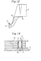
- the conventional magnetic disc device comprises a head actuator having a pivot 6f, as shown in Figure 14.
- the pivot 6f comprises a plurality of head arms 6e which are secured to an outer sleeve 10.
- the outer sleeve 10 is installed on a stationary shaft 12 through two roller bearings 11 and 11'.
- the shaft 12 is disposed on a seat 12a for vertical positioning when secured to the base 1 through a screw.
- the diameter of the seat 12a is approximately the same as that of the outer sleeve 10. Therefore, the space corresponding to the height H of the seat 12a is wasted, thus causing an unnecessary enlarging of the case of the magnetic disc device.
- FIG. 12 A prior art magnetic head structure is illustrated in Figure 12.
- a head 33 is supported at an end of a gimbal 32 which is secured to a head arm 31.
- Information data is transmitted between the head and a read/write device through a lead wire 34.
- a springy clip 35 made of plastic is attached to the head arm 31 to hold the lead wire 34 between the head arm 31 and the clip 35 along the head arm side edge.
- the head arm 31 becomes heavy, since the clip 35 is used for holding the lead wire 34, thus opposing the requirement for reducing the weight of the head arm structure. Also, the gap between the discs must be wide enough to dispose the clips 35 therein, which prevents a reduction of the height of the magnetic device.
- FIG. 5 is a disassembled perspective view of a magnetic disc device according to the present invention.
- the magnetic disc device comprises: a housing formed by a base 1 and a cover 2; four magnetic discs 4 secured to a spindle 3; eight magnetic heads 5 for magnetic read/ write operations at the upper and lower surfaces of each magnetic disc 4; and a head actuator 6 for swinging the magnetic heads 5 in the direction ot the arrow AA' on the magnetic disc surface.
- the head actuator 6 comprises a drive motor 6a; a capstan 6b, a steel belt 6c, a sector 6d, head arms 6e, and a pivot 6f.
- a spindle drive motor (not shown), a printed circuit board for driving the spindle drive motor (not shown), and a main printed circuit board 7 mounting a read/write circuit for reading data from and writing data on the magnetic disc.
- the magnetic head 5 is attached to the head arm 6e through a gimbal spring and a load spring 8.
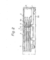
- the magnetic disc device illustrated in Fig. 1 is seen from the upper side thereof, with the cover removed, and Fig. 2 shows a vertical section thereof.
- a bottom plate 30 (Fig. 2) for covering the main printed circuit board 7 is disposed below the base 1 and secured thereto together with the main printed circuit board 7 by screws.
- the height c is the dimension between the lowest surface of the bottom plate 30 and the top surface of the cover 2.
- the gap d between the adjacent magnetic discs 4 is 4.5 mm, and the thickness t of each magnetic disc 4 is 1.27 mm.
- Five head arms 6e are arranged to conduct a seeking motion on both surfaces of the four magnetic discs 4, as shown in Fig. 2.
- the thickness of the two uppermost and lowermost head arms is 2.0 mm, and the thickness of the three intermediate head arms is 2.8 mm.
- the tip of each head arm 6e is thinned to 1.154 mm to attach the load spring 8.
- the gap between the lower surface of the lowermost magnetic disc 4 and the upper surface of the base 1 is 3.5 mm.
- the gap w (Fig. 11) between the lower surface of the lowermost head arm 6e at the pivot portion and the upper surface of the base 1 is 0.5 mm.
- the magnetic discs 4 rotate in the direction of the arrow R (Fig. 1).
- a baffle plate 41 is disposed corresponding to each of the four magnetic discs 4 facing the upper surface thereof, and a filter 2 is incorporated with the baftle plates 41 to capture dust particles on the disc surface.
- the magnetic head 5 is connected to a flexible printed circuit broad 43 (shown by a dash-dot line) bonded behind the head arm 6e through a lead wire 5a'.
- a head IC (preamplifier) 44 is mounted on the flexible printed circuit board 43 behind the head arm 6e.
- the flexible printed circuit board 43 is connected to a connector 45 disposed at a corner of the base 1.
- the flexible printed circuit board 43 is loose and can be folded back and forth within the rear end of the head arm 6e to allow free movement without impeding the swing motion of the head arm 6e.
- the connector 45 is connected to the main printed circuit board 7 (Fig. 5) disposed under the base 1.
- the head arm 6e has a counter weight portion 46 mounted at the side opposite to the magnetic head attaching end thereof with respect to the pivot 6f. With the provision of the counter weight portion 46, it is possible to balance the weight of the head arm 6e with respect to the pivot 6f, thus achieving a smooth and stable swing motion of the head arm irrespective of the-attitude of the device.
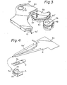
- the swing actuator structure of the head arm 6e is illustrated in detail in Fig. 3.
- the head arm 6e is rotatable about the pivot 6f, as shown by the arrow Q, and a mashroom-shaped sector 6d is secured to the head arm 6e.
- a capstan 6b is disposed facing and adjacent to the head of the sector 6d.
- the capstan 6b is rotatable about a shaft 48, as shown by the arrow P, a tension spring 47 is attached to the stem of the sector 6d, and an end of a steel belt 6c is bonded to the tension spring 47.
- Another steel belt 6c' is secured to the opposite side of the sector 6d. Both steel belts a#e wound around the capstan 6b and secured thereto at the back thereof by a screw.
- Both steel belts may be formed as one integral strip.
- the capstan 6b is rotated as shown by the arrow P to swing the sector 6d through the steel belts 6c, 6c', thus rotating the head arm 6e as shown by the arrow Q about the pivot 6f.
- Numeral 10 designates a groove for holding the lead cable 5a', as described later in detail.
- the structure for supporting the magnetic head 5 is illustrated in detail in Fig. 4.
- the load spring 8 is made from a leaf spring.
- a gimbal 9 also made from a leaf spring is bonded to an end of the load spring 8 by spot welding.
- a support piece 9a is formed by cutting the inner area of the gimbal 9.
- the support piece 9a is bonded to an upper recess surface 50 of the magnetic head 5.
- the magnetic head 5 has a core 5d on which a coil (not shown) is wound and the coil lead 5a is taken out therefrom, as described in detail later.
- the coil lead 5a is covered by a protecting outer tube to form a lead cable 5a' from the end portion of the load spring 8.
- the root portion 8a of the load spring 8 is secured to the end of the head arm 6e (Fig. 5).
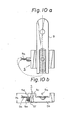
- FIG. 10(a) and 10(b) A magnetic head coil structure according to the present invention is illustrated in Figs. 10(a) and 10(b), wherein Fig. 10(c) is a plan view and Fig. 10(b) is a front view.
- the magnetic head 5 is formed as a slider having a slider surface 5b and a core 5d on which a coil 5e is wound.
- Reference 5a designates a coil lead
- reference 5c designates an opening for forming a gap
- references 5f and 9 designate a gap and a gimbal, respectively.
- the gimbal 9 is bonded to the magnetic head 5 at the hatched portion thereof.
- the lead wire 5a of the coil 5e of the magnetic head 5 is taken from the lateral side of the opening 5c. That is, the coil lead 5a is taken from the intermediate portion of its core 5d along the height thereof instead of the top of the core 5d as in the prior art structure of Fig. 13.
- the height H 1 of this embodiment can be shortened and the distance between the magnetic discs can be reduced without allowing the lead to come into contact with the disc surface, since the lead wire 5a is taken from the lateral side of the opening 5c in parallel with the slider surface 5b.
- the lead wire 5a is disposed along the head arm through the load spring and connected to an amplifier attached behind the head arm.
- the lead wire cable 5a' is fitted and held in a groove 10 formed in a surface of the head arm 6e, to reliably hold the cable and avoid contact between the cable and the disc surface.
- FIG. 11 A pivot structure of the head arm according to the present invention is illustrated in Fig. 11.
- numeral 1 designates a base
- 6e designates a head arm
- 10 designates an outer sleeve
- 11 and 11' designate roller bearings
- 12 designates a stationary shaft.
- this embodiment of the pivot structure comprises the outer sleeve 10, which supports a plurality of head arms 6e simultaneously, and the stationary shaft 12 which rotatably supports the outer sleeve 10 thereon through two roller bearings 11 and 11'.
- the stationary shaft 12 is placed on a seat 12a having a diameter which is approximately the same as that of the outer sleeve 10, to ensure the verticality of the shaft which is secured to the base 1 by a screw, similar to the prior art structure of Fig. 14.
- a primary feature of this embodiment resides in the structure wherein the inner peripheral edge of the lower end of the outer sleeve 10 is inclined and the outer periphery of the seat 12a of the shaft 12 is also inclined in a direction facing the inner inclined lower end of the outer sleeve 10.
- the seat 12a is arranged to fit into the inclined lower inner edge of the outer sleeve 10, thus eliminating the unnecessary dead space corresponding to the height H of the seat as described with reference to Fig. 14 of the,prior art structure. Therefore, it is possible to reduce the height of the magnetic disc device.
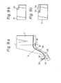
- a coil lead wire cable arrangement according to the present invention is described hereinafter with reference to Figs. 7 to 9.
- Figure 7 is an explanatory view of the principle of the arrangement of the present invention.
- numeral 36 designates a cable holding means comprising a groove formed along the cable pass. The cable 34 is fitted into this groove.
- the cable 34 is fitted and held in the groove of the holding means 36 formed in the head arm 31. Therefore, it is unnecessary to use a special instrument for holding the cable like a clip to hold the cable, thus reducing the weight of the magnetic head structure.
- FIGs. 8(a) and 8(b) An example of the cable holding arrangement according to the present invention is illustrated in Figs. 8(a) and 8(b), wherein the same parts as shown in Fig. 7 are designated by the same numerals.
- Figure 8(a) is a plan view of the arrangement and Fig. 8(b) is a sectional view along the line AAIof Fig. 8(a).
- a groove 37 is formed as a cable holding means along the cable pass on the head arm.
- Figure 8(b) shows a cross section of the groove 37, which comprises a rectangular recess for receiving the cable 34.
- the cable 34 is held in this groove 37 by press fitting the cable into the groove.
- An adhesive agent may be used to firmly hold the cable 34 within the groove 37.
- FIG. 9(a), 9(b) and 9(c) Another example of the cable holding arrangement according to the present invention is illustrated in Fig. 9(a), 9(b) and 9(c).
- a step is formed along the cable pass on the head arm 31, as shown in Fig. 9(b) which shows a cross section along the line BB' of the head arm 31 of Fig. 9(a).
- a plurality of holder projections 38 are disposed along the step of the cable pass to partly form a groove-like portion, as shown in Fig. 9(c) which is a cross section along the line CC' of the head arm 31 of Fig. 9(a).
- the cable 34 is held in this groove-like portion.
- the magnetic head structure according to the present invention comprises a groove as a lead wire holding means formed along the cable pass on the head arm, which makes it unnecessary to use a special cable holding instrument means, thus enabling a reduction of the weight of the magnetic head.
Landscapes
- Supporting Of Heads In Record-Carrier Devices (AREA)
- Moving Of Heads (AREA)
- Adjustment Of The Magnetic Head Position Track Following On Tapes (AREA)
Abstract
Description
- The present invention relates to a magnetic disc device used as a memory for, for example, a mini-computer or a micro-computer.
- Conventionally, a Winchester type magnetic disc device using hard discs 3.5 inch (890 mm) in diameter has been used as a memory means for, for example, a mini-computer or a micro-computer. Such a magnetic disc device should, if possible, have a high memory density without any enlargement of its size, to ensure that it is compatible with other conventional devices.
- A conventional magnetic device typically comprises a record medium on which information data is recorded and a magnetic head for reading the information from that medium. The magnetic head is disposed in such a manner that it faces the recording area of the record medium, to transmit information data between the record medium and a read/write device.
- When a magnetic disc is used as the magnetic medium, the head is attached to a head arm which carries the head and positions it at a desired track in the recording area of the magnetic disc. Therefore, to achieve an accurate positioning of the head at a high speed, it is necessary to reduce the weight of the head construction, including the head arm, to minimise its inertia.
- The height dimension of a magnetic disc device is commercially standardised and a full-height magnetic disc device is marketed. Also, a half-height magnetic disc device has been developed with half the memory capacity to realise a small capacity and size magnetic disc device which is compatible with the full-height magnetic disc device, and advantageous from the standpoint of space saving since the height is a half of that of the full-height magnetic disc device.
- On the other hand, when the capacity of the magnetic disc device is to be increased using an ordinary interface circuit, it is desirable to double the number of the discs it contains, from the standpoint of easy installation of a new magnetic disc device having an increased capacity in place of an old device, since it is easy to exchange an old device with a new one and/or simultaneously use a new device with an old one through an ordinary interface circuit. Therefore, a two-disc magnetic disc device was developed as an improvement on a one-disc magnetic disc device. Subsequently, a magnetic disc device comprising four discs has been developed as an improvement on the two-disc device.
- According to this invention a half-height magnetic disc device comprises:
- a base;
- four magnetic discs arranged one above the other on the base;
- five head arms rotatable about a pivot for seeking motions over both surfaces of each magnetic disc;
- eight magnetic heads each facing a surface of a disc and each attached to an end of a head arm through springy means;
- rotational drive means for swinging the head arms;
- a main printed circuit board arranged under the base; and,
- a cover which covers an upper surface of the base.
- Preferably each magnetic head comprises a slider having a slider surface and a core extending away from the slider surface and having a coil wound on it, a lead wire from the coil being taken out from an intermediate position between the ends of the core.
- Preferably each of the head arms includes a groove in which the lead wire is fitted and held;
- Preferably the pivot comprises:
- an outer sleeve to which the five head arms are secured;
- a stationary shaft secured to the base and on which the outer sleeve is rotatably mounted; and,
- a seat on which the shaft is supported on the base,
- the seat having an inclined periphery, and the outer sleeve having a lower inner annular edge inclined to face the inclined periphery of the seat.
- The present invention makes it possible to house four discs in a half-height magnetic disc device. This could not be realised by the prior art device, since four discs could not be stacked in the shortened half-height device housing when the device had the prior art structure. Preferred aspects of the present invention provide a magnetic disc device in which the problem of a short circuit of the lead wires or an instability of the magnetic head when in operation separated from the disc surface and floating thereon is eliminated. They also provide a magnetic disc device which eliminates unnecessary dead space due to the pivot seat of the head actuator, thus realising a compact device; and providing a magnetic disc device having a light weight head structure.
- Particular embodiments of a magnetic disc device in accordance with this invention will now be described and contrasted with the prior art with reference to the accompanying drawings; in which:-
- Figure 1 is a plan view of a magnetic disc device according to the present invention, with the cover removed;
- Figure 2 is a vertical sectional view of the magnetic disc device according to the present invention;
- Figure 3 is a perspective view of a head arm drive means of the magnetic disc device according to the present invention;
- Figure 4 is a disassembled view of a head support structure of the magnetic disc device according to the present invention;
- Figure 5 is a disassembled view of the magnetic disc device according to the present invention;
- Figure 6 is a view showing a head arm of the magnetic disc device according to the present invention;
- Figure 7 is an explanatory view of the head arm of the magnetic disc device according to the present invention;
- Figures 8(a) and 8(b) are explanatory vies of another example of the head arm, wherein Figure 8(a) is a plan view and Figure 8(b) is a sectional view along the line A-A' of Figure 8(a);
- Figures 9 (a), 9 (b) and 9(c) are explanatory views of still another example of head arm of the present invention, wherein Figure 9(a) is a plan view, Figure 9(b) is a sectional view along the line B-B' of Figure 9(a), and Figure 9(c) is a sectional view along the line C-C' of Figure 9(a);
- Figures 10(a) and 10(b) -are views showing a magnetic head of the present invention, wherein figure 10(a) is a plan view and Figure 10(b) is a front view;
- Figure 11 is a sectional view of a pivot of the magnetic disc device according to the present invention;
- Figure 12 is an explanatory view of a magnetic head arm according to the prior art;
- Figures 13(a) and 13(b) are explanatory views of a magnetic head according to the prior art, wherein Figure 13 (a) is a plan view and Figure 13 (b) is a front view; and,
- Figure 14 is a sectional view of a pivot of a magnetic disc device according to the prior art.
- A conventional magnetic head of a prior art magnetic disc device is illustrated in Figure 13. A
magnetic head 5 comprisescoil lead wires 5a which are drawn upward in the direction opposite to aslider surface 5b. With this structure, thelead wires 5a may sometimes come into contact with a disc surface disposed above the magnetic head or another magnetic head disposed above and opposing thismagnetic head 5 which will cause a short circuit or an instability of the head when in operation separated from the disk surface and floating thereon. - Also, the conventional magnetic disc device comprises a head actuator having a
pivot 6f, as shown in Figure 14. Thepivot 6f comprises a plurality ofhead arms 6e which are secured to anouter sleeve 10. Theouter sleeve 10 is installed on astationary shaft 12 through tworoller bearings 11 and 11'. Theshaft 12 is disposed on aseat 12a for vertical positioning when secured to thebase 1 through a screw. The diameter of theseat 12a is approximately the same as that of theouter sleeve 10. Therefore, the space corresponding to the height H of theseat 12a is wasted, thus causing an unnecessary enlarging of the case of the magnetic disc device. - A prior art magnetic head structure is illustrated in Figure 12. A
head 33 is supported at an end of agimbal 32 which is secured to ahead arm 31. Information data is transmitted between the head and a read/write device through alead wire 34. Aspringy clip 35 made of plastic is attached to thehead arm 31 to hold thelead wire 34 between thehead arm 31 and theclip 35 along the head arm side edge. - With the above-mentioned magnetic head structure of the prior art, the
head arm 31 becomes heavy, since theclip 35 is used for holding thelead wire 34, thus opposing the requirement for reducing the weight of the head arm structure. Also, the gap between the discs must be wide enough to dispose theclips 35 therein, which prevents a reduction of the height of the magnetic device. - Figure 5 is a disassembled perspective view of a magnetic disc device according to the present invention. The magnetic disc device comprises: a housing formed by a
base 1 and acover 2; fourmagnetic discs 4 secured to aspindle 3; eightmagnetic heads 5 for magnetic read/ write operations at the upper and lower surfaces of eachmagnetic disc 4; and ahead actuator 6 for swinging themagnetic heads 5 in the direction ot the arrow AA' on the magnetic disc surface. Thehead actuator 6 comprises adrive motor 6a; acapstan 6b, asteel belt 6c, asector 6d,head arms 6e, and apivot 6f. Below thebase 1 are disposed a spindle drive motor (not shown), a printed circuit board for driving the spindle drive motor (not shown), and a main printedcircuit board 7 mounting a read/write circuit for reading data from and writing data on the magnetic disc. Themagnetic head 5 is attached to thehead arm 6e through a gimbal spring and aload spring 8. - The magnetic disc device illustrated in Fig. 1 is seen from the upper side thereof, with the cover removed, and Fig. 2 shows a vertical section thereof. This magnetic disc device is of a half-height type having a commercially standardized outer shape dimension. That is, the disc diameter is 96 mm, the longitudinal length a = 146 + 0.5 mm, the lateral length b = 101.6 + 0.5 mm, and the height c = 41.3 + 0.3 mm. A bottom plate 30 (Fig. 2) for covering the main printed
circuit board 7 is disposed below thebase 1 and secured thereto together with the main printedcircuit board 7 by screws. The height c is the dimension between the lowest surface of thebottom plate 30 and the top surface of thecover 2. The gap d between the adjacentmagnetic discs 4 is 4.5 mm, and the thickness t of eachmagnetic disc 4 is 1.27 mm. Fivehead arms 6e are arranged to conduct a seeking motion on both surfaces of the fourmagnetic discs 4, as shown in Fig. 2. The thickness of the two uppermost and lowermost head arms is 2.0 mm, and the thickness of the three intermediate head arms is 2.8 mm. The tip of eachhead arm 6e is thinned to 1.154 mm to attach theload spring 8. The gap between the lower surface of the lowermostmagnetic disc 4 and the upper surface of thebase 1 is 3.5 mm. Also, as described later, the gap w (Fig. 11) between the lower surface of thelowermost head arm 6e at the pivot portion and the upper surface of thebase 1 is 0.5 mm. - The
magnetic discs 4 rotate in the direction of the arrow R (Fig. 1). Abaffle plate 41 is disposed corresponding to each of the fourmagnetic discs 4 facing the upper surface thereof, and afilter 2 is incorporated with thebaftle plates 41 to capture dust particles on the disc surface. - The
magnetic head 5 is connected to a flexible printed circuit broad 43 (shown by a dash-dot line) bonded behind thehead arm 6e through alead wire 5a'. A head IC (preamplifier) 44 is mounted on the flexible printedcircuit board 43 behind thehead arm 6e. The flexible printedcircuit board 43 is connected to aconnector 45 disposed at a corner of thebase 1. The flexible printedcircuit board 43 is loose and can be folded back and forth within the rear end of thehead arm 6e to allow free movement without impeding the swing motion of thehead arm 6e. Theconnector 45 is connected to the main printed circuit board 7 (Fig. 5) disposed under thebase 1. - The
head arm 6e has acounter weight portion 46 mounted at the side opposite to the magnetic head attaching end thereof with respect to thepivot 6f. With the provision of thecounter weight portion 46, it is possible to balance the weight of thehead arm 6e with respect to thepivot 6f, thus achieving a smooth and stable swing motion of the head arm irrespective of the-attitude of the device. - The swing actuator structure of the
head arm 6e is illustrated in detail in Fig. 3. Thehead arm 6e is rotatable about thepivot 6f, as shown by the arrow Q, and a mashroom-shapedsector 6d is secured to thehead arm 6e. Acapstan 6b is disposed facing and adjacent to the head of thesector 6d. Thecapstan 6b is rotatable about ashaft 48, as shown by the arrow P, atension spring 47 is attached to the stem of thesector 6d, and an end of asteel belt 6c is bonded to thetension spring 47. Anothersteel belt 6c' is secured to the opposite side of thesector 6d. Both steel belts a#e wound around thecapstan 6b and secured thereto at the back thereof by a screw. Both steel belts may be formed as one integral strip. With this structure, thecapstan 6b is rotated as shown by the arrow P to swing thesector 6d through thesteel belts head arm 6e as shown by the arrow Q about thepivot 6f.Numeral 10 designates a groove for holding thelead cable 5a', as described later in detail. - The structure for supporting the
magnetic head 5 is illustrated in detail in Fig. 4. Theload spring 8 is made from a leaf spring. Agimbal 9 also made from a leaf spring is bonded to an end of theload spring 8 by spot welding. Asupport piece 9a is formed by cutting the inner area of thegimbal 9. Thesupport piece 9a is bonded to anupper recess surface 50 of themagnetic head 5. Themagnetic head 5 has acore 5d on which a coil (not shown) is wound and thecoil lead 5a is taken out therefrom, as described in detail later. Thecoil lead 5a is covered by a protecting outer tube to form alead cable 5a' from the end portion of theload spring 8. Theroot portion 8a of theload spring 8 is secured to the end of thehead arm 6e (Fig. 5). - A magnetic head coil structure according to the present invention is illustrated in Figs. 10(a) and 10(b), wherein Fig. 10(c) is a plan view and Fig. 10(b) is a front view. In the drawings, the
magnetic head 5 is formed as a slider having aslider surface 5b and acore 5d on which acoil 5e is wound.Reference 5a designates a coil lead,reference 5c designates an opening for forming a gap, andreferences gimbal 9 is bonded to themagnetic head 5 at the hatched portion thereof. - As can be seen from the drawings, the
lead wire 5a of thecoil 5e of themagnetic head 5 is taken from the lateral side of theopening 5c. That is, thecoil lead 5a is taken from the intermediate portion of itscore 5d along the height thereof instead of the top of thecore 5d as in the prior art structure of Fig. 13. - The height H1 of this embodiment can be shortened and the distance between the magnetic discs can be reduced without allowing the lead to come into contact with the disc surface, since the
lead wire 5a is taken from the lateral side of theopening 5c in parallel with theslider surface 5b. - The
lead wire 5a is disposed along the head arm through the load spring and connected to an amplifier attached behind the head arm. Preferably, thelead wire cable 5a' is fitted and held in agroove 10 formed in a surface of thehead arm 6e, to reliably hold the cable and avoid contact between the cable and the disc surface. - As mentioned above, in accordance with the present invention, it is possible to reduce the distance between the magnetic discs with a simple structure without allowing the lead wire to come into contact with the magnetic disc surface, thus realizing a compact arrangement of the magnetic discs which is practically very useful.
- A pivot structure of the head arm according to the present invention is illustrated in Fig. 11. In the drawing, numeral 1 designates a base; 6e designates a head arm; 10 designates an outer sleeve; 11 and 11' designate roller bearings; and 12 designates a stationary shaft.
- As shown in the drawing, this embodiment of the pivot structure comprises the
outer sleeve 10, which supports a plurality ofhead arms 6e simultaneously, and thestationary shaft 12 which rotatably supports theouter sleeve 10 thereon through tworoller bearings 11 and 11'. Thestationary shaft 12 is placed on aseat 12a having a diameter which is approximately the same as that of theouter sleeve 10, to ensure the verticality of the shaft which is secured to thebase 1 by a screw, similar to the prior art structure of Fig. 14. A primary feature of this embodiment resides in the structure wherein the inner peripheral edge of the lower end of theouter sleeve 10 is inclined and the outer periphery of theseat 12a of theshaft 12 is also inclined in a direction facing the inner inclined lower end of theouter sleeve 10. - With such a structure, the
seat 12a is arranged to fit into the inclined lower inner edge of theouter sleeve 10, thus eliminating the unnecessary dead space corresponding to the height H of the seat as described with reference to Fig. 14 of the,prior art structure. Therefore, it is possible to reduce the height of the magnetic disc device. - As mentioned above, in accordance with the present invention, it is possible to eliminate the dead space for the pivot seat, with a very simple structure, thus realizing a small-sized magnetic disc device which is practically very useful. This is because the distance w (Fig. 11) between the lower surface of the
head arm 6e and the upper surface of thebase 1 is considerably reduced. - A coil lead wire cable arrangement according to the present invention is described hereinafter with reference to Figs. 7 to 9.
- Figure 7 is an explanatory view of the principle of the arrangement of the present invention. In Fig. 7, numeral 36 designates a cable holding means comprising a groove formed along the cable pass. The
cable 34 is fitted into this groove. - The
cable 34 is fitted and held in the groove of the holding means 36 formed in thehead arm 31. Therefore, it is unnecessary to use a special instrument for holding the cable like a clip to hold the cable, thus reducing the weight of the magnetic head structure. - An example of the cable holding arrangement according to the present invention is illustrated in Figs. 8(a) and 8(b), wherein the same parts as shown in Fig. 7 are designated by the same numerals. Figure 8(a) is a plan view of the arrangement and Fig. 8(b) is a sectional view along the line AAIof Fig. 8(a). A
groove 37 is formed as a cable holding means along the cable pass on the head arm. Figure 8(b) shows a cross section of thegroove 37, which comprises a rectangular recess for receiving thecable 34. - The
cable 34 is held in thisgroove 37 by press fitting the cable into the groove. An adhesive agent may be used to firmly hold thecable 34 within thegroove 37. - Another example of the cable holding arrangement according to the present invention is illustrated in Fig. 9(a), 9(b) and 9(c). A step is formed along the cable pass on the
head arm 31, as shown in Fig. 9(b) which shows a cross section along the line BB' of thehead arm 31 of Fig. 9(a). A plurality ofholder projections 38 are disposed along the step of the cable pass to partly form a groove-like portion, as shown in Fig. 9(c) which is a cross section along the line CC' of thehead arm 31 of Fig. 9(a). Thecable 34 is held in this groove-like portion. - As mentioned above, the magnetic head structure according to the present invention comprises a groove as a lead wire holding means formed along the cable pass on the head arm, which makes it unnecessary to use a special cable holding instrument means, thus enabling a reduction of the weight of the magnetic head.
Claims (12)
Applications Claiming Priority (6)
| Application Number | Priority Date | Filing Date | Title |
|---|---|---|---|
| JP85144/86U | 1986-06-04 | ||
| JP1986085144U JPS62202616U (en) | 1986-06-04 | 1986-06-04 | |
| JP109459/86U | 1986-07-18 | ||
| JP1986109459U JPS6316617U (en) | 1986-07-18 | 1986-07-18 | |
| JP1986110030U JPS6316660U (en) | 1986-07-19 | 1986-07-19 | |
| JP110030/86U | 1986-07-19 |
Related Child Applications (1)
| Application Number | Title | Priority Date | Filing Date |
|---|---|---|---|
| EP91200324.1 Division-Into | 1991-02-15 |
Publications (3)
| Publication Number | Publication Date |
|---|---|
| EP0248650A2 true EP0248650A2 (en) | 1987-12-09 |
| EP0248650A3 EP0248650A3 (en) | 1988-10-26 |
| EP0248650B1 EP0248650B1 (en) | 1992-04-22 |
Family
ID=27304778
Family Applications (2)
| Application Number | Title | Priority Date | Filing Date |
|---|---|---|---|
| EP91200324A Expired - Lifetime EP0432145B1 (en) | 1986-06-04 | 1987-06-03 | Magnetic disc device |
| EP87304907A Expired - Lifetime EP0248650B1 (en) | 1986-06-04 | 1987-06-03 | Magnetic disc device |
Family Applications Before (1)
| Application Number | Title | Priority Date | Filing Date |
|---|---|---|---|
| EP91200324A Expired - Lifetime EP0432145B1 (en) | 1986-06-04 | 1987-06-03 | Magnetic disc device |
Country Status (4)
| Country | Link |
|---|---|
| US (3) | US5060100A (en) |
| EP (2) | EP0432145B1 (en) |
| KR (2) | KR880000947A (en) |
| DE (2) | DE3778427D1 (en) |
Cited By (8)
| Publication number | Priority date | Publication date | Assignee | Title |
|---|---|---|---|---|
| EP0298748A3 (en) * | 1987-07-10 | 1990-07-04 | Kabushiki Kaisha Toshiba | Magnetic disk apparatus |
| EP0494033A1 (en) * | 1990-12-31 | 1992-07-08 | International Business Machines Corporation | Rotary actuator for disk drive assemblies |
| EP0522717A3 (en) * | 1991-07-12 | 1993-03-31 | Seagate Technology International | Pivot mechanism for a rotary actuator |
| EP0536891A1 (en) * | 1991-09-12 | 1993-04-14 | International Business Machines Corporation | Disk drive apparatus |
| EP0632432A3 (en) * | 1989-05-01 | 1995-03-29 | Seagate Technology | Pivot support for actuator arm. |
| EP0712129A4 (en) * | 1993-07-30 | 1996-12-27 | Citizen Watch Co Ltd | Magnetic disc device |
| EP0766233A3 (en) * | 1991-06-10 | 1998-01-07 | Fujitsu Limited | Magnetic disk drive |
| EP0903741A3 (en) * | 1990-07-06 | 1999-04-14 | Seagate Technology, Inc. | Low height disk drive |
Families Citing this family (46)
| Publication number | Priority date | Publication date | Assignee | Title |
|---|---|---|---|---|
| US5621582A (en) * | 1988-01-25 | 1997-04-15 | Conner Peripherals, Inc. | Disk drive including a baseplate well for the spin motor |
| US5956213A (en) | 1988-01-25 | 1999-09-21 | Seagate Technology, Inc. | Latch mechanism for disk drive using magnetic field of actuator magnets |
| US5245486A (en) * | 1989-05-20 | 1993-09-14 | Fujitsu Limited | Disk unit with a side mounted board |
| US5490027A (en) * | 1991-10-28 | 1996-02-06 | Censtor Corp. | Gimbaled micro-head/flexure/conductor assembly and system |
| JP2935129B2 (en) * | 1990-05-28 | 1999-08-16 | インターナショナル・ビジネス・マシーンズ・コーポレーション | Fixed magnetic disk drive and related apparatus and method |
| JP2645606B2 (en) * | 1990-09-03 | 1997-08-25 | 富士通株式会社 | Rotary actuator structure |
| US5276572A (en) * | 1990-09-19 | 1994-01-04 | Hitachi, Ltd. | Magnetic disk apparatus |
| US5074029A (en) * | 1990-10-02 | 1991-12-24 | International Business Machines Corporation | Method for stringing wire on an actuator arm |
| JP3436757B2 (en) * | 1991-11-22 | 2003-08-18 | シーゲイト テクノロジー エルエルシー | Latch mechanism for actuator arm |
| US5396388A (en) * | 1992-02-27 | 1995-03-07 | Censtor Corp. | Compact, high-speed, rotary actuator and transducer assembly with reduced moment of inertia and mass-balanced structural overlap with drive motor and organizing method for the same |
| DE69318228T2 (en) * | 1992-08-04 | 1998-08-27 | Seagate Technology | Voice coil motor and plate unit |
| JP2725977B2 (en) * | 1992-08-28 | 1998-03-11 | インターナショナル・ビジネス・マシーンズ・コーポレイション | Magnetoresistive sensor, method of manufacturing the same, and magnetic storage system |
| US5636086A (en) * | 1993-05-28 | 1997-06-03 | International Business Machines Corporation | Roll insensitive air bearing slider |
| DE69407299T2 (en) * | 1993-08-23 | 1998-05-28 | Heath John Stewart | ARM BEARING WITH ROLLER MOVEMENT FOR A DISK DRIVE |
| KR0135109B1 (en) * | 1994-04-23 | 1998-04-22 | 김광호 | Flexible printed circuit (FPC) connector on hard disk drive |
| JP3199977B2 (en) | 1995-03-17 | 2001-08-20 | 富士通株式会社 | Disk unit |
| JPH097145A (en) * | 1995-06-15 | 1997-01-10 | Fujitsu Ltd | Disk device actuator arm assembly |
| JP3400248B2 (en) * | 1995-08-30 | 2003-04-28 | インターナショナル・ビジネス・マシーンズ・コーポレーション | Head suspension load beam for disk drive devices |
| US5710680A (en) * | 1995-12-22 | 1998-01-20 | Pc Peripherals Inc. | Magnetic hard disk drive head suspension apparatus |
| US5912787A (en) * | 1996-10-07 | 1999-06-15 | Magnecomp Corp. | Disk drive suspension with minimum wire-induced bias |
| US6011671A (en) * | 1997-04-10 | 2000-01-04 | Seagate Technology, Inc. | Head gimbal assembly for limiting dimple separation for a data storage device |
| US6900962B1 (en) * | 1997-09-05 | 2005-05-31 | Seagate Technology Llc | High performance standard configuration disc drive having smaller-than-standard discs |
| US6288866B1 (en) * | 1999-11-19 | 2001-09-11 | Western Digital Technologies, Inc. | Disk drive including a vibration damping system having a compressible foam and mass damper fixed adjacent to the outer surface of a printed circuit board for reducing noise and vibration |
| US6775104B2 (en) | 2000-09-27 | 2004-08-10 | Seagate Technology Llc | Actuator arm damper with integrated pre-amplifier |
| JP2002170345A (en) * | 2000-11-29 | 2002-06-14 | Internatl Business Mach Corp <Ibm> | Head assembly, disk drive device, hard disk drive and manufacture of disk drive device |
| US6882501B2 (en) * | 2000-11-30 | 2005-04-19 | Maxtor Corporation | Flow modification for reducing track misregistration in hard disk drives |
| US6762908B2 (en) * | 2001-06-18 | 2004-07-13 | Samsung Electronics Co., Ltd. | Air razor and disk limiter for a hard disk drive |
| US6754046B2 (en) | 2001-09-20 | 2004-06-22 | Seagate Technology Llc | Increased slip force pivot bearing |
| US6754045B2 (en) | 2002-01-03 | 2004-06-22 | Seagate Tech. Llc | Electrical interconnect with a retaining feature for an actuator assembly |
| US6826009B1 (en) * | 2002-08-30 | 2004-11-30 | General Electric Capital Corporation | Disk drive including a filter element disposed along a disk surface for filtering disk rotation induced airflow |
| KR100524981B1 (en) | 2003-08-07 | 2005-10-31 | 삼성전자주식회사 | Actuator with absorption filter and disk drive having the same |
| US7145753B1 (en) * | 2004-05-15 | 2006-12-05 | Western Digital Technologies, Inc. | Head stack assembly with insulated wiring extending between actuator coil and actuator main body section disposed in lateral wiring protector extending from actuator body |
| US8102621B2 (en) * | 2009-10-15 | 2012-01-24 | Hitachi Global Storage Technologies Netherlands B.V. | Integrated upstream spoiler and particle filter in a hard-disk drive (HDD) |
| US8355220B2 (en) * | 2009-12-14 | 2013-01-15 | HGST Netherlands B.V. | Upstream spoiler with integrated crash stop |
| US10410681B1 (en) * | 2018-07-23 | 2019-09-10 | Seagate Technology Llc | Printed circuit board snap-in mounting |
| TWI856233B (en) | 2020-01-29 | 2024-09-21 | 美商艾德凡斯化學公司 | Amino acid surfactants |
| TWI786519B (en) | 2020-01-29 | 2022-12-11 | 美商艾德凡斯化學公司 | Amino acid surfactants |
| MX2022011056A (en) | 2020-03-11 | 2022-12-06 | Advansix Resins & Chemicals Llc | Surfactants for electronics products. |
| US12071600B2 (en) | 2020-03-11 | 2024-08-27 | Advansix Resins & Chemicals Llc | Surfactants for cleaning products |
| UA129170C2 (en) | 2020-03-11 | 2025-01-29 | Адвансікс Резінс Енд Чемікалс Ллс | SURFACTANTS FOR PERSONAL HYGIENE AND COSMETIC PRODUCTS |
| CA3261735A1 (en) | 2020-03-11 | 2025-04-02 | Advansix Resins & Chemicals Llc | Surfactants for inks, paints, and adhesives |
| MX2022011122A (en) | 2020-03-11 | 2022-10-03 | Advansix Resins & Chemicals Llc | Surfactants for agricultural products. |
| JP2023517664A (en) | 2020-03-11 | 2023-04-26 | アドバンシックス・レジンズ・アンド・ケミカルズ・リミテッド・ライアビリティ・カンパニー | Surfactants for oil and gas production |
| US11423931B2 (en) * | 2020-11-14 | 2022-08-23 | Western Digital Technologies, Inc. | Data storage device interleave driving secondary actuators |
| US11482254B2 (en) * | 2021-02-15 | 2022-10-25 | Western Digital Technologies, Inc. | Data storage device independently driving outer and inner fine actuators |
| US11482246B2 (en) * | 2021-02-15 | 2022-10-25 | Western Digital Technologies, Inc. | Data storage device independently driving outer and inner fine actuators |
Family Cites Families (29)
| Publication number | Priority date | Publication date | Assignee | Title |
|---|---|---|---|---|
| US3931641A (en) * | 1974-08-22 | 1976-01-06 | International Business Machines Corporation | Transducer suspension mount apparatus |
| JPS5149012A (en) * | 1974-10-24 | 1976-04-27 | Suwa Seikosha Kk | JIKIKIOKUSOCHI |
| US4161004A (en) * | 1977-04-05 | 1979-07-10 | Shugart Associates | Head positioning mechanism for recording/playback machine |
| DE2723140C2 (en) * | 1977-05-23 | 1986-06-12 | Basf Ag, 6700 Ludwigshafen | Device for positioning objects |
| FR2420809A1 (en) * | 1978-03-24 | 1979-10-19 | Cii Honeywell Bull | READ-WRITE DEVICE FOR AN INFORMATION MEDIA WITH LOW-LOAD RAMP TAKING |
| US4164766A (en) * | 1978-04-24 | 1979-08-14 | Data General Corporation | Disc memory apparatus magnetic head carriage manual control |
| US4194225A (en) * | 1978-06-06 | 1980-03-18 | International Memories, Inc. | Housing for disk drive unit |
| USRE32702F1 (en) * | 1978-11-03 | 1991-03-05 | Brushless d.c.motor assembly | |
| US4352134A (en) * | 1979-11-19 | 1982-09-28 | International Business Machines Corporation | Magnetic head assembly with corrosion resistant conductive wire |
| US4422115A (en) * | 1980-02-29 | 1983-12-20 | Digital Equipment Corporation | Lightweight dual head support assembly for magnetic disk drives |
| US4367502A (en) * | 1980-04-11 | 1983-01-04 | Shugart Technology | Fixed hard disc drive assembly and clean air system |
| EP0060358B1 (en) * | 1981-03-18 | 1984-11-21 | International Business Machines Corporation | Head support arm and head/arm assemblies for disk files |
| JPS57191872A (en) * | 1981-05-20 | 1982-11-25 | Fujitsu Ltd | Magnetic head |
| US4415821A (en) * | 1982-05-10 | 1983-11-15 | Kollmorgen Technologies Corporation | Dynamic magnetic preload bearing structure for a linear motor |
| AT378301B (en) * | 1983-06-17 | 1985-07-25 | Philips Nv | SYSTEM FOR PLAYING BACK SIGNALS STORED ON A MAGNETIC TAPE |
| JPS6035319A (en) * | 1983-08-04 | 1985-02-23 | Fuji Photo Film Co Ltd | Tracking device of rotary magnetic recording body |
| JPS60133569A (en) * | 1983-12-21 | 1985-07-16 | Hitachi Ltd | Magnetic disc device |
| JPS60138789A (en) * | 1983-12-27 | 1985-07-23 | Toshiba Corp | Assembling method of magnetic head |
| US4568988A (en) * | 1984-02-22 | 1986-02-04 | Rodime Plc | Micro hard-disk drive system |
| DE3412231A1 (en) * | 1984-04-02 | 1985-10-03 | Nixdorf Computer Ag, 4790 Paderborn | CARRIER ARRANGEMENT FOR MAGNETIC HEADS OF A MAGNETIC DISK DRIVE |
| JPS6166216A (en) * | 1984-09-07 | 1986-04-05 | Hitachi Ltd | magnetic head |
| JPS6190079U (en) * | 1984-11-16 | 1986-06-11 | ||
| US4647997A (en) * | 1985-04-29 | 1987-03-03 | Plus Development Corporation | Aerodynamic latch for disk file actuator |
| DE8519878U1 (en) * | 1985-07-10 | 1985-10-17 | Basf Ag, 6700 Ludwigshafen | Device for positioning objects of low mass, in particular at least one magnetic head, with respect to a second object, in particular on at least one magnetic disk |
| US4707754A (en) * | 1985-08-07 | 1987-11-17 | Apple Computer, Inc. | Voice coil balanced actuator |
| US5023733A (en) * | 1985-12-16 | 1991-06-11 | Seiko Epson Corporation | Head positioning control for a spindle motor disk drive |
| US4716478A (en) * | 1986-02-14 | 1987-12-29 | Hewlett-Packard Company | Two point attachment with single point clamping for connecting the arm stack to the actuator member in a disc memory drive |
| JPH0424552Y2 (en) * | 1986-07-18 | 1992-06-10 | ||
| US4805055A (en) * | 1986-11-24 | 1989-02-14 | Maxtor | Winchester disc drive actuator structure |
-
1987
- 1987-06-03 DE DE8787304907T patent/DE3778427D1/en not_active Expired - Lifetime
- 1987-06-03 EP EP91200324A patent/EP0432145B1/en not_active Expired - Lifetime
- 1987-06-03 DE DE3789391T patent/DE3789391T2/en not_active Expired - Fee Related
- 1987-06-03 EP EP87304907A patent/EP0248650B1/en not_active Expired - Lifetime
- 1987-06-04 KR KR870005657A patent/KR880000947A/en active Granted
- 1987-06-04 KR KR1019870005657A patent/KR910001715B1/en not_active Expired
-
1990
- 1990-01-11 US US07/463,838 patent/US5060100A/en not_active Expired - Fee Related
-
1994
- 1994-02-17 US US08/197,541 patent/US5418666A/en not_active Expired - Lifetime
-
1995
- 1995-01-04 US US08/368,640 patent/US5646800A/en not_active Expired - Lifetime
Cited By (11)
| Publication number | Priority date | Publication date | Assignee | Title |
|---|---|---|---|---|
| EP0298748A3 (en) * | 1987-07-10 | 1990-07-04 | Kabushiki Kaisha Toshiba | Magnetic disk apparatus |
| EP0632432A3 (en) * | 1989-05-01 | 1995-03-29 | Seagate Technology | Pivot support for actuator arm. |
| EP0903741A3 (en) * | 1990-07-06 | 1999-04-14 | Seagate Technology, Inc. | Low height disk drive |
| EP0494033A1 (en) * | 1990-12-31 | 1992-07-08 | International Business Machines Corporation | Rotary actuator for disk drive assemblies |
| US5283704A (en) * | 1990-12-31 | 1994-02-01 | International Business Machines Corporation | Rotary actuator for disk drive assemblies |
| EP0766233A3 (en) * | 1991-06-10 | 1998-01-07 | Fujitsu Limited | Magnetic disk drive |
| US5969907A (en) * | 1991-06-10 | 1999-10-19 | Fujitsu Limited | Magnetic disk drive |
| EP0522717A3 (en) * | 1991-07-12 | 1993-03-31 | Seagate Technology International | Pivot mechanism for a rotary actuator |
| EP0536891A1 (en) * | 1991-09-12 | 1993-04-14 | International Business Machines Corporation | Disk drive apparatus |
| EP0712129A4 (en) * | 1993-07-30 | 1996-12-27 | Citizen Watch Co Ltd | Magnetic disc device |
| US5671103A (en) * | 1993-07-30 | 1997-09-23 | Citizen Watch Co., Ltd. | Sealed, dust-proof magnetic disk drive |
Also Published As
| Publication number | Publication date |
|---|---|
| KR880000947A (en) | 1988-03-30 |
| US5646800A (en) | 1997-07-08 |
| KR910001715B1 (en) | 1991-03-19 |
| EP0248650A3 (en) | 1988-10-26 |
| EP0432145A3 (en) | 1992-05-06 |
| DE3789391D1 (en) | 1994-04-21 |
| US5060100A (en) | 1991-10-22 |
| EP0432145A2 (en) | 1991-06-12 |
| DE3778427D1 (en) | 1992-05-27 |
| EP0248650B1 (en) | 1992-04-22 |
| EP0432145B1 (en) | 1994-03-16 |
| US5418666A (en) | 1995-05-23 |
| DE3789391T2 (en) | 1994-06-23 |
Similar Documents
| Publication | Publication Date | Title |
|---|---|---|
| EP0248650A2 (en) | Magnetic disc device | |
| US4890176A (en) | Crash stop and magnetic latch for a voice coil actuator | |
| US5224000A (en) | Crash stop and magnetic latch for a voice coil actuator | |
| EP0556302B1 (en) | Multiple actuator disk drive | |
| US5343345A (en) | Magnetic disk storage apparatus with multiple sets of actuator arms for read/write operations at different circumferential locations within the disk stack | |
| US4814913A (en) | Compact magnetic disc assembly | |
| US4947274A (en) | Resiliently mounted crash stop and magnetic latch for a voice coil actuator | |
| US5986852A (en) | High capacity, high performance low profile disk drive | |
| EP0494033A1 (en) | Rotary actuator for disk drive assemblies | |
| JPH0351778Y2 (en) | ||
| EP0484658A1 (en) | Compact disk drive | |
| US6243228B1 (en) | Information storage and retrieval device | |
| US4924337A (en) | Disk drive servo shield | |
| JPH0963215A (en) | Disk unit | |
| JPH0346172A (en) | Integral type head fixing assembly of hard disc drive | |
| US20050135001A1 (en) | Magnetic recording device | |
| JPH0233322Y2 (en) | ||
| JP3688445B2 (en) | Magnetic disk unit | |
| JP2789770B2 (en) | Transducer positioning device | |
| JPS6093673A (en) | Magnetic recording device | |
| JPS6292111A (en) | Disc storage device | |
| JP2005092909A (en) | Head gimbal assembly, head stack assembly, and magnetic disk drive | |
| JPS6289276A (en) | Magnetic head positioning mechanism of magnetic disk device | |
| JPH06295544A (en) | Magnetic head assembly and magnetic disk device using the magnetic head assembly | |
| JPH0294078A (en) | Recording and reproducing device |
Legal Events
| Date | Code | Title | Description |
|---|---|---|---|
| PUAI | Public reference made under article 153(3) epc to a published international application that has entered the european phase |
Free format text: ORIGINAL CODE: 0009012 |
|
| AK | Designated contracting states |
Kind code of ref document: A2 Designated state(s): DE GB IT |
|
| PUAL | Search report despatched |
Free format text: ORIGINAL CODE: 0009013 |
|
| AK | Designated contracting states |
Kind code of ref document: A3 Designated state(s): DE GB IT |
|
| 17P | Request for examination filed |
Effective date: 19890413 |
|
| 17Q | First examination report despatched |
Effective date: 19901012 |
|
| ITF | It: translation for a ep patent filed | ||
| GRAA | (expected) grant |
Free format text: ORIGINAL CODE: 0009210 |
|
| AK | Designated contracting states |
Kind code of ref document: B1 Designated state(s): DE GB IT |
|
| XX | Miscellaneous (additional remarks) |
Free format text: TEILANMELDUNG 91200324.1 EINGEREICHT AM 03/06/87. |
|
| REF | Corresponds to: |
Ref document number: 3778427 Country of ref document: DE Date of ref document: 19920527 |
|
| ITTA | It: last paid annual fee | ||
| PLBE | No opposition filed within time limit |
Free format text: ORIGINAL CODE: 0009261 |
|
| STAA | Information on the status of an ep patent application or granted ep patent |
Free format text: STATUS: NO OPPOSITION FILED WITHIN TIME LIMIT |
|
| 26N | No opposition filed | ||
| PGFP | Annual fee paid to national office [announced via postgrant information from national office to epo] |
Ref country code: GB Payment date: 19930521 Year of fee payment: 7 |
|
| PG25 | Lapsed in a contracting state [announced via postgrant information from national office to epo] |
Ref country code: GB Effective date: 19940603 |
|
| PGFP | Annual fee paid to national office [announced via postgrant information from national office to epo] |
Ref country code: DE Payment date: 19940608 Year of fee payment: 8 |
|
| GBPC | Gb: european patent ceased through non-payment of renewal fee |
Effective date: 19940603 |
|
| PG25 | Lapsed in a contracting state [announced via postgrant information from national office to epo] |
Ref country code: DE Effective date: 19960301 |
|
| PG25 | Lapsed in a contracting state [announced via postgrant information from national office to epo] |
Ref country code: IT Free format text: LAPSE BECAUSE OF NON-PAYMENT OF DUE FEES;WARNING: LAPSES OF ITALIAN PATENTS WITH EFFECTIVE DATE BEFORE 2007 MAY HAVE OCCURRED AT ANY TIME BEFORE 2007. THE CORRECT EFFECTIVE DATE MAY BE DIFFERENT FROM THE ONE RECORDED. Effective date: 20050603 |