EP0248613A2 - Heat transfer systems - Google Patents
Heat transfer systems Download PDFInfo
- Publication number
- EP0248613A2 EP0248613A2 EP87304806A EP87304806A EP0248613A2 EP 0248613 A2 EP0248613 A2 EP 0248613A2 EP 87304806 A EP87304806 A EP 87304806A EP 87304806 A EP87304806 A EP 87304806A EP 0248613 A2 EP0248613 A2 EP 0248613A2
- Authority
- EP
- European Patent Office
- Prior art keywords
- rotary machine
- gas
- heat
- region
- casing
- Prior art date
- Legal status (The legal status is an assumption and is not a legal conclusion. Google has not performed a legal analysis and makes no representation as to the accuracy of the status listed.)
- Withdrawn
Links
Images


Classifications
-
- F—MECHANICAL ENGINEERING; LIGHTING; HEATING; WEAPONS; BLASTING
- F01—MACHINES OR ENGINES IN GENERAL; ENGINE PLANTS IN GENERAL; STEAM ENGINES
- F01C—ROTARY-PISTON OR OSCILLATING-PISTON MACHINES OR ENGINES
- F01C20/00—Control of, monitoring of, or safety arrangements for, machines or engines
- F01C20/10—Control of, monitoring of, or safety arrangements for, machines or engines characterised by changing the positions of the inlet or outlet openings with respect to the working chamber
- F01C20/16—Control of, monitoring of, or safety arrangements for, machines or engines characterised by changing the positions of the inlet or outlet openings with respect to the working chamber using lift valves
-
- F—MECHANICAL ENGINEERING; LIGHTING; HEATING; WEAPONS; BLASTING
- F01—MACHINES OR ENGINES IN GENERAL; ENGINE PLANTS IN GENERAL; STEAM ENGINES
- F01C—ROTARY-PISTON OR OSCILLATING-PISTON MACHINES OR ENGINES
- F01C1/00—Rotary-piston machines or engines
- F01C1/30—Rotary-piston machines or engines having the characteristics covered by two or more groups F01C1/02, F01C1/08, F01C1/22, F01C1/24 or having the characteristics covered by one of these groups together with some other type of movement between co-operating members
- F01C1/40—Rotary-piston machines or engines having the characteristics covered by two or more groups F01C1/02, F01C1/08, F01C1/22, F01C1/24 or having the characteristics covered by one of these groups together with some other type of movement between co-operating members having the movement defined in group F01C1/08 or F01C1/22 and having a hinged member
- F01C1/44—Rotary-piston machines or engines having the characteristics covered by two or more groups F01C1/02, F01C1/08, F01C1/22, F01C1/24 or having the characteristics covered by one of these groups together with some other type of movement between co-operating members having the movement defined in group F01C1/08 or F01C1/22 and having a hinged member with vanes hinged to the inner member
-
- F—MECHANICAL ENGINEERING; LIGHTING; HEATING; WEAPONS; BLASTING
- F01—MACHINES OR ENGINES IN GENERAL; ENGINE PLANTS IN GENERAL; STEAM ENGINES
- F01C—ROTARY-PISTON OR OSCILLATING-PISTON MACHINES OR ENGINES
- F01C11/00—Combinations of two or more machines or engines, each being of rotary-piston or oscillating-piston type
- F01C11/002—Combinations of two or more machines or engines, each being of rotary-piston or oscillating-piston type of similar working principle
- F01C11/004—Combinations of two or more machines or engines, each being of rotary-piston or oscillating-piston type of similar working principle and of complementary function, e.g. internal combustion engine with supercharger
-
- F—MECHANICAL ENGINEERING; LIGHTING; HEATING; WEAPONS; BLASTING
- F02—COMBUSTION ENGINES; HOT-GAS OR COMBUSTION-PRODUCT ENGINE PLANTS
- F02G—HOT GAS OR COMBUSTION-PRODUCT POSITIVE-DISPLACEMENT ENGINE PLANTS; USE OF WASTE HEAT OF COMBUSTION ENGINES; NOT OTHERWISE PROVIDED FOR
- F02G5/00—Profiting from waste heat of combustion engines, not otherwise provided for
- F02G5/02—Profiting from waste heat of exhaust gases
-
- F—MECHANICAL ENGINEERING; LIGHTING; HEATING; WEAPONS; BLASTING
- F24—HEATING; RANGES; VENTILATING
- F24H—FLUID HEATERS, e.g. WATER OR AIR HEATERS, HAVING HEAT-GENERATING MEANS, e.g. HEAT PUMPS, IN GENERAL
- F24H1/00—Water heaters, e.g. boilers, continuous-flow heaters or water-storage heaters
-
- F—MECHANICAL ENGINEERING; LIGHTING; HEATING; WEAPONS; BLASTING
- F25—REFRIGERATION OR COOLING; COMBINED HEATING AND REFRIGERATION SYSTEMS; HEAT PUMP SYSTEMS; MANUFACTURE OR STORAGE OF ICE; LIQUEFACTION SOLIDIFICATION OF GASES
- F25B—REFRIGERATION MACHINES, PLANTS OR SYSTEMS; COMBINED HEATING AND REFRIGERATION SYSTEMS; HEAT PUMP SYSTEMS
- F25B27/00—Machines, plants or systems, using particular sources of energy
-
- Y—GENERAL TAGGING OF NEW TECHNOLOGICAL DEVELOPMENTS; GENERAL TAGGING OF CROSS-SECTIONAL TECHNOLOGIES SPANNING OVER SEVERAL SECTIONS OF THE IPC; TECHNICAL SUBJECTS COVERED BY FORMER USPC CROSS-REFERENCE ART COLLECTIONS [XRACs] AND DIGESTS
- Y02—TECHNOLOGIES OR APPLICATIONS FOR MITIGATION OR ADAPTATION AGAINST CLIMATE CHANGE
- Y02B—CLIMATE CHANGE MITIGATION TECHNOLOGIES RELATED TO BUILDINGS, e.g. HOUSING, HOUSE APPLIANCES OR RELATED END-USER APPLICATIONS
- Y02B30/00—Energy efficient heating, ventilation or air conditioning [HVAC]
- Y02B30/52—Heat recovery pumps, i.e. heat pump based systems or units able to transfer the thermal energy from one area of the premises or part of the facilities to a different one, improving the overall efficiency
-
- Y—GENERAL TAGGING OF NEW TECHNOLOGICAL DEVELOPMENTS; GENERAL TAGGING OF CROSS-SECTIONAL TECHNOLOGIES SPANNING OVER SEVERAL SECTIONS OF THE IPC; TECHNICAL SUBJECTS COVERED BY FORMER USPC CROSS-REFERENCE ART COLLECTIONS [XRACs] AND DIGESTS
- Y02—TECHNOLOGIES OR APPLICATIONS FOR MITIGATION OR ADAPTATION AGAINST CLIMATE CHANGE
- Y02E—REDUCTION OF GREENHOUSE GAS [GHG] EMISSIONS, RELATED TO ENERGY GENERATION, TRANSMISSION OR DISTRIBUTION
- Y02E20/00—Combustion technologies with mitigation potential
- Y02E20/14—Combined heat and power generation [CHP]
-
- Y—GENERAL TAGGING OF NEW TECHNOLOGICAL DEVELOPMENTS; GENERAL TAGGING OF CROSS-SECTIONAL TECHNOLOGIES SPANNING OVER SEVERAL SECTIONS OF THE IPC; TECHNICAL SUBJECTS COVERED BY FORMER USPC CROSS-REFERENCE ART COLLECTIONS [XRACs] AND DIGESTS
- Y02—TECHNOLOGIES OR APPLICATIONS FOR MITIGATION OR ADAPTATION AGAINST CLIMATE CHANGE
- Y02T—CLIMATE CHANGE MITIGATION TECHNOLOGIES RELATED TO TRANSPORTATION
- Y02T10/00—Road transport of goods or passengers
- Y02T10/10—Internal combustion engine [ICE] based vehicles
- Y02T10/12—Improving ICE efficiencies
Definitions
- This invention relates to heat transfer systems and rotary machines.
- a heat transfer system comprises:
- the rotary machine may be connected to drive a heat pump for heating fluid.
- One form of system may have a further rotary machine having compressor and expander regions, the flow of gas being for compression in the further rotary machine before compression in the first-mentioned rotary machine, the gas passing from the second heat exchanger to the expander region of the further rotary machine and then to the first heat exchanger.
- the further rotary machine may be connected to drive a heat pump for heating fluid.
- Another form of system may have a further rotary machine having compressor and expander regions, the flow of gas being compression in the further rotary machine, then flow through a third heat exchanger in the fluid flow line to heat the fluid, then compression in the first-mentioned rotary machine, then through the second heat exchanger to heat the gas, then through the heater, then through the expander region of the first rotary machine, then through the second heat exchanger to heat the gas, then through the first heat exchanger to heat the fluid, then through the expander region of the further rotary machine.
- the first and third heat exchangers may be in parallel.
- the heater may be a combustor in which the gas is heated by combustion with fuel.
- the system may include a control system including devices responsive to temperature in the fluid flow line upstream and downstream of the first and third heat exchangers for increasing or decreasing fuel flow.
- the arrangement may be such that the temperature of the heated fluid is within upper and lower limits.
- the invention provides a rotary machine having a rotor eccentrically mounted in a casing having axial end parts and a circumferential part and with vanes defining compartments with the casing and providing a compression region and an expansion region, valve means in the circumferential part adjacent the upstream edge of the outlet from one- or both of the regions and responsive to pressure in the adjacent, compartment to reduce or avoid excess pressure in the compression region or suction in the expansion region.
- the rotary machine may have valve means in the circumferential part adjacent the downstream edge of the inlet of the compression region and responsive to pressure in the adjacent compartment to reduce or avoid suction in the expansion region.
- the invention provides a rotary machine having a rotor eccentrically mounted in a casing with vanes defining compartments with the casing and providing a compression region and expansion region, in which the rotor has axial parts between which the vanes are located, the axial parts comprising inner and outer parts between which is a heat barrier.
- British Patent Specification 2039328 describes a power system and British Patent Specification 2010401 and US Patent Specification 4362014 describes rotary machines and form a background to the present invention.
- a fluid heating system 10 is shown schematically in Fig. 1.
- a fluid which could be a liquid or a gas, to be heated is fed on feed line or pipe 11 and part of the flow goes on line 12 through heat exchanger 13 and then to a return line 14 and the remainder of the flow goes on line 15 through heat exchanger 16 and then to the return line 14.
- Means indicated at 17 in line 12 may be provided for varying the relative proportion of the flow in line 11 which goes through the respective heat exchangers 13, 16.
- the fluid In passing through each of the heat exchangers 13, 16 the fluid is heated and receives heat from a flow of gas, for example air or other combustible gas.
- Flow of gas is as indicated by arrows in Fig. 1.
- the gas passes first through a fan 20 to increase the speed of flow, then through a low pressure compression stage in a rotary compressor/expander machine 21 from which it emerges at a higher pressure (e.g. 65 pounds per square inch absolute (PSIA) (4 bars) and (e.g. 184°C) temperature to flow through heat exchanger 13 from which the now-cooler gas flows to a second, highpressure, rotary compressor/expander machine 22 from which the gas emerges at a higher temperature and pressure (e.g. 130 PSIA) (8 bars).
- PSIA pounds per square inch absolute
- the gas then flows through a heat exchanger 23, where the gas is heated, then through a combustor 24 in which the gas is heated by combustion with fuel, and then flows through an expander part of compressor/expander machine 22 where the gas loses heat and pressure and drives the machine 22, emerging from the machine at a pressure for example 65 PSIA (4 bars).
- the gas then flows through heat exchanger 23 in which the gas is cooled, giving up heat to the gas flowing to combustor 24.
- the now-cooler gas then flows through heat exchanger 16 where the gas gives up'heat to the fluid in line 15 and, further cooled, the gas passes to an expander part of machine 21 where the gas expands (for example to atmospheric pressure) and cools, driving the machine 21.
- Fig. 1 Examples of gas temperature in °Celsius are indicated on Fig. 1 and it will be noted the gas temperature leaving the expander part of machine 21 is below the freezing point of water so that the gas could pass to a device where it acts as a coolant.
- the rotary machines 21, 22 are coupled for synchronous rotation as indicated schematically at 25.
- the heated fluid in line 14- may for example be used to heat domestic or industrial radiators.
- a control system 30 for the heating system 10 is shown in Fig. 2, for use with liquid fuel in combustor 24.
- a similar control system could be used for gaseous fuel.
- a control unit 31 is linked to temperature- responsive sensors 32, 33 associated with the feed and return lines 11, 14.
- Fuel from a supply tank (not shown) is drawn on pipe 34 by a pump 35 and passes through a metering-valve 36 and a pressurizing valve 37 to the burner or combustor 24.
- a pressure relief valve 38 is connected to the pipe 34 between the pump and the metering valve.
- a valve member 40 of valve 36 is connected for rotation with a cam 39.
- the member 40 has a series of angularly spaced orifices 41 of different sizes which can be selectively placed in the flow in pipe 34.
- the unit 31 rotates valve member 40 so that a larger orifice, or more orifices, are brought into pipe 34, to increase fuel flow.
- the valve member 40 continues to rotate until the temperature in the feed line reaches 25 0 c or the temperature in the return line reaches 85 0 c. If the feed line 11 reaches 27°c or the return line reaches 87°c, the unit 31 moves the valve member 40 to close the pipe 34 until the temperature in the feed line is 25 0 c and the temperature in the return line is 85°c or less.
- a shut-off valve 48 which may be manually or electrically operated, is provided so that when operated the pipe 34 is closed and a cam 42 is operated through a shaft 43 to open a dump valve 44 connecting the pipe 34 to a drain pipe 45 leading to the supply tank.
- the pipe 45 also receives any leakage from valves 36, 38, 48 through connections 46, 47.
- the machines 21, 22 are rotary machines of the kind comprising:
- Such machines can be adapted to perform either an engine function by allowing a hot inlet gas to expand in the compartments as the compartments increase in volume or a compressor function by supplying an inlet gas to be compressed in the compartments as the compartments decrease in volume.
- the machines may have radially slidable vanes but preferably are as described in British patent 2010401 and US patent 4362014 with some modifications described hereinafter. In general such a machine comprises:
- the main static parts of the engine comprise the casing 202; casing pillar 210 with axis 203; and static axle 205 with axis 201.
- the main rotating parts of the engine comprise the rotor 200 which has a saw-tooth periphery and is rotatable about axis 201 of axle 205; vanes 206, rotatable about axes 207 at the roots of the saw teeth; cranks 208; and connecting arms 209. As shown in Fig. 6 the vanes 206 substantially fully radially occupy the eccentric annulus 204 (indicated by "dimension" lines 204).
- an input or output shaft 220 integral with a sealing, bearing and lubricating front plate 221 and rear plate 222.
- a sealing, bearing and lubricating front plate 221 and rear plate 222 Between the plates 221, 222 there is the main body 223 (200) of the rotor.
- the rotor is carried on bearings 224, 225, 228 and the vanes 206 are supported on bearings 226, 227, in the plates 221, 222.
- the block 230 defines a radial exhaust port 233.
- the form and location of inlet ports will be determined by the function the machine has to perform.
- Oil passages 239 are indicated.
- the expansion of the supplied gas typically takes place in the peripheral compartments 211 as they increase in volume and once they are beyond the supply cut-off point... This expansion applies a driving torque to the shaft 220. As the compartments 211 change in volume, the expanded gas is exposed to an exhaust port 233 which may typically angularly extend over about 5 / 12 of the circumference.
- Fig. 7 illustrates machine 21 having casing 60 with expansion inlet region 61, expansion exhaust port region 62, compressor inlet region 63, and compressor outlet region 64.
- the vane tip will have reached point A at the point of maximum compression. If fuel supply is now reduced or there is a change in working efficiency, the vane will reach the angular point of appropriate compression before point A, e.g. point B, and to avoid over-pressure being obtained as a result of rotation from B to A, valves are provided, responsive to pressure in the adjacent compartment., The. valves control ports in region 66 of the casing. There are typically nine valves 65 giving a nine-step adjustment and they are located as shown in Fig. 8 indicating the edge C of the exhaust port.
- Each valve is associated with a respective sensor 65a for the compartment pressure at the circumferential position of the valve and connected to the pressure tapping described later.
- the connection is indicated schematically at 65b for valves 1, 8 but omitted for the other valves for clarity.
- the valves overlap so that the angular extent of any overpressurizing is reduced or eliminated.
- Overpressurizing should preferably be of angular extent of no more than a half valve diameter.
- the sensors 65a are located in the circumferential part of the casing and may comprise a hollow tube .communicating at an inner end with an aperture in the casing and at an outer end with connection 65b. Region 66 is immediately upstream of the upstream edge of the outlet 64 from the compression region.
- Valves 65 are located in region 75, to avoid suction in the expansion stage, and in region 76, to avoid over-pressure in the compression stage, with typical locations of the valve ports in region 76 shown in Fig. 10. There may typically be nine valves 65 in region 75.
- valves 65 also immediately downstream of the inlet regions 61, 71 in casing regions 63a, 73a. This enables the acceleration of the rotor to be increased by increasing the drive torque as a result of admitting more gas into the inlet region via the valves.
- a suitable valve 65 is shown in Fig. 11.
- the valve has a stem 80 for closing the respective port, and inner and outer parts 81, 82 secured together by bolt 83.
- a piston 84 is slidable in chamber 85 in part 82 and has a through vent 86 and is connected to bellows seal 87, being held in place on stem 80 by nut 88. Pressure tappings 89, 90 communicate with opposite sides of the piston.
- the compressors and expanders automatically compensate for changes brought about by the fuel control system or a change in their working efficiency in the following way:-The low pressure compressor anti-overpressurisation valves are spring loaded closed by their bellows, the inner-most pressure tapping 89 is used to sense the pressure inside the machine annulus (i.e. the adjacent compartment) and the outer pressure tapping 90 is connected on line 65c to the high pressure expansion exhaust outlet.
- the high pressure compressor anti-overpressurisation valves are spring loaded closed by their bellow, the inner-most pressure tapping is used to sense the pressure inside the machine annulus.
- the outer-most tapping is connected to combustion pressure at combustor inlet 24a.
- the high pressure expansion exhaust anti-suction valves are spring-loaded open by their bellows, the outer-most pressure tapping is used to sense the pressure inside the machine annulus.
- the inner-most pressure tapping is connected to the high pressure expansion exhaust outlet on line 65c.
- the heat output is greater than the heat input of the fuel, some of the heat in the output being taken from atmosphere.
- the described arrangement provides a heat pump system.
- exhaust temperatures of for example 205°K (about - 70°C)
- a volume of about 1/10 of the volume heated by the heated fluid can be cooled to deep freeze temperatures.
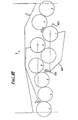
- Fig. 12 shows another heat transfer system 100 in which like parts to Figs. 1-11 have like numerals.
- the machine 22 is arranged to drive by shaft 25 a heat pump 110 which receives fluid to be heated (liquid or gas) on line 111 and-discharges heated fluid on line 112, the heated fluid being available for example for heating.
- a heat pump 110 which receives fluid to be heated (liquid or gas) on line 111 and-discharges heated fluid on line 112, the heated fluid being available for example for heating.
- the shaft 25 may drive an electric generator 113 which in turn drives the heat pump 110.
- Fig. 13 the system has two rotary machines 21, 22 and heated fluid is again available on lines 108a and 112.
- the number of vanes and associated parts in the rotary machines may vary and would typically be six or more.
- the outer surface 206a of the vanes is shaped to conform to the inner surface of the casing with running clearance. It is desirable to have as large a number of vanes as convenient and practical.
- Fig. 15 shows a longitudinal section through a modified rotor, vane, drive arm and spokes in which the rotor 200 is mounted in plain bearings 225a, 228a.
- Fig. 16 shows another arrangement allowing higher operating temperatures, for example as appropriate for use as an internal combustion engine rather than as a compressor.
- additional annular side discs 221a, 222a providing annular recesses 221d, 222d are secured to the sides of the rotor and bolted thereto by a tie bolt 290 (see also Fig. 14).
- the outer parts 221, 222 of of the side discs have inner extensions 221b, 222b bolted to each-other and to radial inner tongue 291 of rotor 200 at 222c.
- the higher temperatures e.g.
- 400°C) appropriate for use as an internal combustion engine might preclude oil lubrication of the hot rotor but by splitting the side discs in this way with recesses 221d, 222d and limited area of contact between inner and outer discs the axially outer side discs 221, 222 although rotating with the rotor remain sufficiently cool for oil lubrication of bearings 225a, 228a as indicated at 228b, the recesses forming heat barriers.
- thrust bearings 300 are provided (Fig. 17) to resist axial movement of vanes and maintain a running clearance between the side of the vanes and the side discs 221, 222 or 221a, 222a.
- Fig. 18 shows a modified rotor for use as part of a combustion engine.
- the rotor When the rotor is used as part of a combustion engine the rotor will run at temperatures greater than 400°C and the casing temperature will vary . circumferentially.
- the casing needs to be controlled by locally cooling or locally moving to maintain a running clearance of typically less-than 0.05mm on smaller engines and 0.2mm on larger engines.
- This sort of problem is usually solved by varying the air flow round the casing and hence varying the cooling effect, but in the present case because the casing outside the rotor path is divided by the inlet and outlet ports it is possible to have radially adjustable segments of the rotor path.
- the radial position of the segments can be controlled by proximity sensors with the segments sliding against fixed parts of the casing.
- Movement of rotor path segments G, H and J is ⁇ 0.5mm in direction-of arrows.
- Electronic sensors S control actuators to position the segments in close proximity to the rotating vane tips.
- Actuators 301 e.g. stepper motors can move casing segments through gearing.
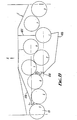
- FIG. 19 shows a further arrangement.
- a gas generator 310 drives a heat pump drive unit 311 which drives a heat pump 312.
- the gas generator 310 comprises a rotary machine 313 acting as a low pressure compressor mechanically coupled at 314 to rotate with a rotary machine 315 arranged as a high pressure compressor/expander. Air or other combustible gas inlet 317 to the machine 313 enables the pressure and temperature of the gas to be increased and the gas passes on line 318 to the compression side of machine 315 where the temperature and pressure of the gas is increased.
- the gas then passes on line 319 to a gas combustor 320 in which the gas is heated to for example between 5000C and 1000°C by burning with fuel and the hot gases of combustion then pass on line 321 to the expander part of machine 315 where the gas pressure and temperature are reduced as the gas drives the machine 315 and thus the machine 313.
- the gas pressure reduces in machine 315 approximately to the outlet pressure of machine 313.
- the gas then passes on line 322 to a rotary machine 311 mechanically coupled at 324 to drive a heat pump 312 having fluid input 326 and heated fluid output 327.
- the gas expands in machine 311 to drive the machine 311.
- the gas exhausted from machine 311 may pass to atmosphere or may be used to assist in heating the refrigerant medium in a heat exchanger 330 in the heat pump at the appropriate point in the refrigerant medium heating/cooling cycle.
- the rotary machines are as described above.
- the fluid temperature in inlet 326 may vary, for example in consequence of changes in ambient temperature e.g. in a domestic heating system.
- the power requirements of the heat pump drive unit will also alter and this alters the following:
- the effect of (a) and/or (b) and/or (c) is to vary the combustor 320 pressure and temperature.
- Sensors 331 in line 326 may control the fuel flow to the combustor to for example maintain a constant temperature in outlet 327. Varying the fuel flow will vary the delivery pressure from machine 315; this can be separately varied by adjusting sensors 65a or valves 65 to vary the expansion or compressor outlet pressure at which the valves operate.
- the combustor 320, 24 can be replaced by a heat exchanger receiving heat from a suitable source.
Landscapes
- Engineering & Computer Science (AREA)
- Mechanical Engineering (AREA)
- General Engineering & Computer Science (AREA)
- Chemical & Material Sciences (AREA)
- Combustion & Propulsion (AREA)
- Physics & Mathematics (AREA)
- Thermal Sciences (AREA)
- Applications Or Details Of Rotary Compressors (AREA)
- Engine Equipment That Uses Special Cycles (AREA)
- Rotary Pumps (AREA)
Abstract
Description
- This invention relates to heat transfer systems and rotary machines.
- According to the invention a heat transfer system comprises:
- a fluid flow line,
- a first heat exchanger in the fluid flow line,
- a second heat exchanger,
- a rotary machine having compressor and expander regions,
- a heater for heating gas,
- . a flow conduit for flow of gas for compression in the rotary machine, then flow through the second heat exchanger to heat the gas, then flow through the heater, then through the expander region of the rotary machine, and then through the second heat exchanger to effect heating of the gas flow, then through the first heat exchanger to heat the fluid.
- The rotary machine may be connected to drive a heat pump for heating fluid.
- One form of system may have a further rotary machine having compressor and expander regions, the flow of gas being for compression in the further rotary machine before compression in the first-mentioned rotary machine, the gas passing from the second heat exchanger to the expander region of the further rotary machine and then to the first heat exchanger.
- The further rotary machine may be connected to drive a heat pump for heating fluid.
- Another form of system may have a further rotary machine having compressor and expander regions, the flow of gas being compression in the further rotary machine, then flow through a third heat exchanger in the fluid flow line to heat the fluid, then compression in the first-mentioned rotary machine, then through the second heat exchanger to heat the gas, then through the heater, then through the expander region of the first rotary machine, then through the second heat exchanger to heat the gas, then through the first heat exchanger to heat the fluid, then through the expander region of the further rotary machine.
- The first and third heat exchangers may be in parallel.
- The heater may be a combustor in which the gas is heated by combustion with fuel.
- The system may include a control system including devices responsive to temperature in the fluid flow line upstream and downstream of the first and third heat exchangers for increasing or decreasing fuel flow.
- The arrangement may be such that the temperature of the heated fluid is within upper and lower limits.
- From another aspect the invention provides a rotary machine having a rotor eccentrically mounted in a casing having axial end parts and a circumferential part and with vanes defining compartments with the casing and providing a compression region and an expansion region, valve means in the circumferential part adjacent the upstream edge of the outlet from one- or both of the regions and responsive to pressure in the adjacent, compartment to reduce or avoid excess pressure in the compression region or suction in the expansion region.
- The rotary machine may have valve means in the circumferential part adjacent the downstream edge of the inlet of the compression region and responsive to pressure in the adjacent compartment to reduce or avoid suction in the expansion region.
- From a further aspect the invention provides a rotary machine having a rotor eccentrically mounted in a casing with vanes defining compartments with the casing and providing a compression region and expansion region, in which the rotor has axial parts between which the vanes are located, the axial parts comprising inner and outer parts between which is a heat barrier.
- British Patent Specification 2039328 describes a power system and British Patent Specification 2010401 and US Patent Specification 4362014 describes rotary machines and form a background to the present invention.
- The invention. may be performed in various ways and some specific embodiments with.possible modifications will now be described by way of example with reference to the accompanying somewhat diagrammatic drawings, in which:
- Fig. 1 shows a heat transfer system;
- Fig. 2 is a control system;
- Fig. 3 is a view of a valve member;
- Fig. 4 is a representation of a rotor of a rotary machine;
- Fig. 5 is a mechanical coupling for driving vanes;
- Fig. 6 is a sectional side view of part of a device using the rotor of Fig. 3;
- Fig. 7 shows a rotor;
- Fig. 8 shows porting for the rotor of Fig. 7;
- Fig. 9 shows another rotor;
- Fig. 10 shows porting for the rotor of Fig. 9;
- Fig. 11 is a section through a valve;
- Fig. 12 shows another heat transfer system;
- Fig. 13 shows a further heat transfer system;
- Fig. 14 shows a modified vane arrangement;
- Fig. 15 shows a modified rotor;
- Fig. 16 shows a further rotor;
- Fig. 17 shows another modification;
- Fig. 18 shows another rotor; and
- Fig. 19 shows a heating circuit.
- A
fluid heating system 10 is shown schematically in Fig. 1. A fluid, which could be a liquid or a gas, to be heated is fed on feed line orpipe 11 and part of the flow goes on line 12 throughheat exchanger 13 and then to areturn line 14 and the remainder of the flow goes online 15 throughheat exchanger 16 and then to thereturn line 14. Means indicated at 17 in line 12 may be provided for varying the relative proportion of the flow inline 11 which goes through therespective heat exchangers heat exchangers - Flow of gas is as indicated by arrows in Fig. 1. The gas passes first through a
fan 20 to increase the speed of flow, then through a low pressure compression stage in a rotary compressor/expander machine 21 from which it emerges at a higher pressure (e.g. 65 pounds per square inch absolute (PSIA) (4 bars) and (e.g. 184°C) temperature to flow throughheat exchanger 13 from which the now-cooler gas flows to a second, highpressure, rotary compressor/expander machine 22 from which the gas emerges at a higher temperature and pressure (e.g. 130 PSIA) (8 bars). The gas then flows through aheat exchanger 23, where the gas is heated, then through acombustor 24 in which the gas is heated by combustion with fuel, and then flows through an expander part of compressor/expander machine 22 where the gas loses heat and pressure and drives themachine 22, emerging from the machine at a pressure for example 65 PSIA (4 bars). The gas then flows throughheat exchanger 23 in which the gas is cooled, giving up heat to the gas flowing tocombustor 24. The now-cooler gas then flows throughheat exchanger 16 where the gas gives up'heat to the fluid inline 15 and, further cooled, the gas passes to an expander part ofmachine 21 where the gas expands (for example to atmospheric pressure) and cools, driving themachine 21. Examples of gas temperature in °Celsius are indicated on Fig. 1 and it will be noted the gas temperature leaving the expander part ofmachine 21 is below the freezing point of water so that the gas could pass to a device where it acts as a coolant. -Therotary machines - A
control system 30 for theheating system 10 is shown in Fig. 2, for use with liquid fuel incombustor 24. A similar control system could be used for gaseous fuel. - A
control unit 31 is linked to temperature-responsive sensors 32, 33 associated with the feed andreturn lines pipe 34 by apump 35 and passes through a metering-valve 36 and a pressurizingvalve 37 to the burner orcombustor 24. Apressure relief valve 38 is connected to thepipe 34 between the pump and the metering valve. Avalve member 40 ofvalve 36 is connected for rotation with acam 39. Themember 40 has a series of angularly spaced orifices 41 of different sizes which can be selectively placed in the flow inpipe 34. When the temperature of fluid in theline 11 falls, for example, to 210C theunit 31 rotatesvalve member 40 so that a larger orifice, or more orifices, are brought intopipe 34, to increase fuel flow. Thevalve member 40 continues to rotate until the temperature in the feed line reaches 250c or the temperature in the return line reaches 850c. If thefeed line 11 reaches 27°c or the return line reaches 87°c, theunit 31 moves thevalve member 40 to close thepipe 34 until the temperature in the feed line is 250c and the temperature in the return line is 85°c or less. - A shut-off
valve 48, which may be manually or electrically operated, is provided so that when operated thepipe 34 is closed and a cam 42 is operated through ashaft 43 to open a dump valve 44 connecting thepipe 34 to a drain pipe 45 leading to the supply tank. The pipe 45 also receives any leakage fromvalves connections 46, 47. - The
machines - (a) a casing;
- (b) a rotor rotatable eccentrically in, or with one part of, the casing and having means to define with, or with another part of, the casing, peripheral compartments which are separate from each other;
- (c) an inlet for the inflow of a medium to the compartments sequentially as the rotor rotates;
- (d) an outlet, displaced in the direction of rotation of the rotor from the inlet, for the outflow of said medium, and
- (e) a shaft whereby power can be supplied to or taken from said rotor.
- Such machines can be adapted to perform either an engine function by allowing a hot inlet gas to expand in the compartments as the compartments increase in volume or a compressor function by supplying an inlet gas to be compressed in the compartments as the compartments decrease in volume. The machines may have radially slidable vanes but preferably are as described in British patent 2010401 and US patent 4362014 with some modifications described hereinafter. In general such a machine comprises:
- (a) a casing;
- (b) a rotor rotatable eccentrically in the casing to define an eccentric annulus and having vanes pivotably secured to the periphery of the rotor to define with the casing compartments in the eccentric annulus which are separate from each other;
- (c) an inlet opening for the inflow of a medium to the compartments sequentially as the rotor rotates;
- (d) an outlet, displaced in the direction of rotation of the rotor from the inlet, for the outflow of said medium;
- (e) a coupling whereby power can be supplied to or taken from said rotor;
- (f) crank arms movable in planes parallel to but displaced from the planes occupied by the vanes and oscillating arms rotatably oscillatable about a pillar which is fixed in relation to the casing, the oscillating arms being secured to the crank arms to mechanically pivot the crank arms and hence the vanes to their operative positions. Referring to Figs. 4 to 6, in Fig. 4 there is shown a rotary engine having an
engine rotor 200 with anaxis 201 and a fixed trulycylindrical casing 202 withaxis 203. Therotor 200 is seen to be eccentric in thecasing 202 and defines with the casing aneccentric annulus 204. The rotor is rotatable on astatic axle 205 and is equipped with twelve angularly spacedvanes 206 carried on pivots, indicated byaxes 207, and running in the casing with a very small clearance between their tips and the casing..The-vanes 206 are each respectively mechanically coupled to cranks 208 (now see Fig. 5) and the cranks are oscillated by respective connectingarms 209 mounted on acasing pillar 210, that is, aboutaxis 203. The vanes defineperipheral compartments 211 in the eccentric annulus which cyclically change in volume as the rotor rotates. The rotor is arranged for rotation in the direction of arrow x. The outer surface ofthe'vanes 206 could be curved so that when the compartments have smallest volume this surface substantially conforms to the inner surface of the casing and has a running clearance therewith. - Components.200 to 210 are also indicated in Fig. 6 which will now be described.
- The main static parts of the engine comprise the
casing 202; casingpillar 210 withaxis 203; andstatic axle 205 withaxis 201. - The main rotating parts of the engine comprise the
rotor 200 which has a saw-tooth periphery and is rotatable aboutaxis 201 ofaxle 205;vanes 206, rotatable aboutaxes 207 at the roots of the saw teeth; cranks 208; and connectingarms 209. As shown in Fig. 6 thevanes 206 substantially fully radially occupy the eccentric annulus 204 (indicated by "dimension" lines 204). - Other parts of the rotor are: an input or
output shaft 220 integral with a sealing, bearing and lubricatingfront plate 221 andrear plate 222. Between theplates bearings vanes 206 are supported onbearings plates - Other parts- of the casing are: the
main block 230, thefront cover plate 231 andrear cover plate 232. Theblock 230 defines aradial exhaust port 233. The form and location of inlet ports will be determined by the function the machine has to perform. -
Oil passages 239 are indicated. - The expansion of the supplied gas typically takes place in the
peripheral compartments 211 as they increase in volume and once they are beyond the supply cut-off point... This expansion applies a driving torque to theshaft 220. As thecompartments 211 change in volume, the expanded gas is exposed to anexhaust port 233 which may typically angularly extend over about 5/12 of the circumference. - Fig. 7 illustrates
machine 21 havingcasing 60 withexpansion inlet region 61, expansionexhaust port region 62,compressor inlet region 63, andcompressor outlet region 64. At maximum design power and fuel consumption the vane tip will have reached point A at the point of maximum compression. If fuel supply is now reduced or there is a change in working efficiency, the vane will reach the angular point of appropriate compression before point A, e.g. point B, and to avoid over-pressure being obtained as a result of rotation from B to A, valves are provided, responsive to pressure in the adjacent compartment., The. valves control ports in region 66 of the casing. There are typically ninevalves 65 giving a nine-step adjustment and they are located as shown in Fig. 8 indicating the edge C of the exhaust port. - Each valve is associated with a
respective sensor 65a for the compartment pressure at the circumferential position of the valve and connected to the pressure tapping described later. The connection is indicated schematically at 65b forvalves - The
sensors 65a are located in the circumferential part of the casing and may comprise a hollow tube .communicating at an inner end with an aperture in the casing and at an outer end withconnection 65b. Region 66 is immediately upstream of the upstream edge of theoutlet 64 from the compression region. - Similarly in the case of
machine 22 there is anexpansion inlet region 71 Fig. 9, expansion exhaust port region 72,compressor inlet region 73, compressor outlet region 74.Valves 65 are located inregion 75, to avoid suction in the expansion stage, and inregion 76, to avoid over-pressure in the compression stage, with typical locations of the valve ports inregion 76 shown in Fig. 10. There may typically be ninevalves 65 inregion 75. - It is preferable to have
valves 65 also immediately downstream of theinlet regions casing regions 63a, 73a. This enables the acceleration of the rotor to be increased by increasing the drive torque as a result of admitting more gas into the inlet region via the valves. - A
suitable valve 65 is shown in Fig. 11. The valve has astem 80 for closing the respective port, and inner andouter parts 81, 82 secured together bybolt 83. Apiston 84 is slidable inchamber 85 inpart 82 and has a throughvent 86 and is connected to bellows seal 87, being held in place onstem 80 bynut 88.Pressure tappings 89, 90 communicate with opposite sides of the piston. - The compressors and expanders automatically compensate for changes brought about by the fuel control system or a change in their working efficiency in the following way:-The low pressure compressor anti-overpressurisation valves are spring loaded closed by their bellows, the inner-most pressure tapping 89 is used to sense the pressure inside the machine annulus (i.e. the adjacent compartment) and the outer pressure tapping 90 is connected on line 65c to the high pressure expansion exhaust outlet.
- The high pressure compressor anti-overpressurisation valves are spring loaded closed by their bellow, the inner-most pressure tapping is used to sense the pressure inside the machine annulus. The outer-most tapping is connected to combustion pressure at combustor inlet 24a.
- The high pressure expansion exhaust anti-suction valves are spring-loaded open by their bellows, the outer-most pressure tapping is used to sense the pressure inside the machine annulus. The inner-most pressure tapping is connected to the high pressure expansion exhaust outlet on line 65c.
- If desired there may be similar anti-suction valves immediately upstream of the low pressure exhaust opening.
- With the described machine the heat output is greater than the heat input of the fuel, some of the heat in the output being taken from atmosphere.
- The described arrangement provides a heat pump system. With exhaust temperatures of for example 205°K (about - 70°C) a volume of about 1/10 of the volume heated by the heated fluid can be cooled to deep freeze temperatures.
- Fig. 12 shows another heat transfer system 100 in which like parts to Figs. 1-11 have like numerals.
- In this case there is one
rotary machine 22 receiving gas input flow online 101 which after being compressed and heated inmachine 22 is fed online 102 throughheat exchanger 23, in which the gas is further heated, and thence online 103 to combustor 24- where the gas is further heated and then on line 104- to the expander side of themachine 22, then at reduced temperature and pressure online 105 throughheat exchanger 23 where the gas is cooled and then passes online 106 to aheat exchanger 107 where the gas transfers heat to a fluid (liquid or gas) inline 108 the heated fluid being available online 108a for example for domestic or industrial radiators. The gas passes to exhaust online 109. - The
machine 22 is arranged to drive by shaft 25 aheat pump 110 which receives fluid to be heated (liquid or gas) on line 111 and-discharges heated fluid online 112, the heated fluid being available for example for heating. - Instead of
shaft 25 driving theheat pump 110 direct, theshaft 25 may drive anelectric generator 113 which in turn drives theheat pump 110. - In Fig. 13 the system has two
rotary machines lines - The number of vanes and associated parts in the rotary machines may vary and would typically be six or more. For example as shown in Fig. 14 there could be six
vanes 206. Preferably the outer surface 206a of the vanes is shaped to conform to the inner surface of the casing with running clearance. It is desirable to have as large a number of vanes as convenient and practical. - Fig. 15 shows a longitudinal section through a modified rotor, vane, drive arm and spokes in which the
rotor 200 is mounted inplain bearings 225a, 228a. There are twoarms 209 for each vane e.g.'at 209a, connected to the rotor as indicated, one having a central connection at 209b of double thickness. - Fig. 16 shows another arrangement allowing higher operating temperatures, for example as appropriate for use as an internal combustion engine rather than as a compressor. In this arrangement additional annular side discs 221a, 222a providing annular recesses 221d, 222d are secured to the sides of the rotor and bolted thereto by a tie bolt 290 (see also Fig. 14). The
outer parts inner extensions inner tongue 291 ofrotor 200 at 222c. The higher temperatures (e.g. 400°C) appropriate for use as an internal combustion engine might preclude oil lubrication of the hot rotor but by splitting the side discs in this way with recesses 221d, 222d and limited area of contact between inner and outer discs the axiallyouter side discs bearings 225a, 228a as indicated at 228b, the recesses forming heat barriers. - Preferably thrust
bearings 300 are provided (Fig. 17) to resist axial movement of vanes and maintain a running clearance between the side of the vanes and theside discs - Fig. 18 shows a modified rotor for use as part of a combustion engine. When the rotor is used as part of a combustion engine the rotor will run at temperatures greater than 400°C and the casing temperature will vary . circumferentially. The casing needs to be controlled by locally cooling or locally moving to maintain a running clearance of typically less-than 0.05mm on smaller engines and 0.2mm on larger engines. This sort of problem is usually solved by varying the air flow round the casing and hence varying the cooling effect, but in the present case because the casing outside the rotor path is divided by the inlet and outlet ports it is possible to have radially adjustable segments of the rotor path. The radial position of the segments can be controlled by proximity sensors with the segments sliding against fixed parts of the casing. Movement of rotor path segments G, H and J is ± 0.5mm in direction-of arrows. Electronic sensors S control actuators to position the segments in close proximity to the rotating vane tips. Actuators 301 (only one shown) e.g. stepper motors can move casing segments through gearing.
- Fig. 19 shows a further arrangement. A
gas generator 310 drives a heatpump drive unit 311 which drives aheat pump 312. Thegas generator 310 comprises arotary machine 313 acting as a low pressure compressor mechanically coupled at 314 to rotate with arotary machine 315 arranged as a high pressure compressor/expander. Air or othercombustible gas inlet 317 to themachine 313 enables the pressure and temperature of the gas to be increased and the gas passes online 318 to the compression side ofmachine 315 where the temperature and pressure of the gas is increased. The gas then passes online 319 to agas combustor 320 in which the gas is heated to for example between 5000C and 1000°C by burning with fuel and the hot gases of combustion then pass online 321 to the expander part ofmachine 315 where the gas pressure and temperature are reduced as the gas drives themachine 315 and thus themachine 313. The gas pressure reduces inmachine 315 approximately to the outlet pressure ofmachine 313. The gas then passes online 322 to arotary machine 311 mechanically coupled at 324 to drive aheat pump 312 havingfluid input 326 andheated fluid output 327. The gas expands inmachine 311 to drive themachine 311. The gas exhausted frommachine 311 may pass to atmosphere or may be used to assist in heating the refrigerant medium in a heat exchanger 330 in the heat pump at the appropriate point in the refrigerant medium heating/cooling cycle. - The rotary machines are as described above.
- Under operating conditions the fluid temperature in
inlet 326 may vary, for example in consequence of changes in ambient temperature e.g. in a domestic heating system. As a consequence the power requirements of the heat pump drive unit will also alter and this alters the following: - (a) The fuel flow to the gas
generator combustion chamber 320 and/or - (b) the delivery pressure from the gas
generator HP compressor 315 and/or - (c) the outlet pres'sure from the gas generator turbine 305.
- The effect of (a) and/or (b) and/or (c) is to vary the
combustor 320 pressure and temperature. -
Sensors 331 inline 326 may control the fuel flow to the combustor to for example maintain a constant temperature inoutlet 327. Varying the fuel flow will vary the delivery pressure frommachine 315; this can be separately varied by adjustingsensors 65a orvalves 65 to vary the expansion or compressor outlet pressure at which the valves operate. - The
combustor
Claims (17)
Applications Claiming Priority (2)
| Application Number | Priority Date | Filing Date | Title |
|---|---|---|---|
| GB868613414A GB8613414D0 (en) | 1986-06-03 | 1986-06-03 | Heat transfer systems |
| GB8613414 | 1986-06-03 |
Publications (2)
| Publication Number | Publication Date |
|---|---|
| EP0248613A2 true EP0248613A2 (en) | 1987-12-09 |
| EP0248613A3 EP0248613A3 (en) | 1988-11-23 |
Family
ID=10598835
Family Applications (1)
| Application Number | Title | Priority Date | Filing Date |
|---|---|---|---|
| EP87304806A Withdrawn EP0248613A3 (en) | 1986-06-03 | 1987-06-01 | Heat transfer systems |
Country Status (4)
| Country | Link |
|---|---|
| US (1) | US4831827A (en) |
| EP (1) | EP0248613A3 (en) |
| JP (1) | JPS62298607A (en) |
| GB (2) | GB8613414D0 (en) |
Cited By (3)
| Publication number | Priority date | Publication date | Assignee | Title |
|---|---|---|---|---|
| WO1996039571A1 (en) * | 1995-06-06 | 1996-12-12 | P. D. T. Engineering Technology Limited | Rotary positive-displacement fluid machine |
| EP0803639A1 (en) * | 1996-04-26 | 1997-10-29 | BAKKER, Albert | Hot gas motor and compressor unit |
| WO1998057039A1 (en) * | 1997-06-11 | 1998-12-17 | Driver Technology Limited | Rotary positive-displacement fluid machines |
Families Citing this family (4)
| Publication number | Priority date | Publication date | Assignee | Title |
|---|---|---|---|---|
| WO2003062604A2 (en) * | 2002-01-17 | 2003-07-31 | E.A. Technical Services Limited | Rotary positive displacement machine |
| GB0413442D0 (en) * | 2004-06-16 | 2004-07-21 | Ea Technical Services Ltd | Rolling piston stirling engine |
| US20090050080A1 (en) * | 2007-08-24 | 2009-02-26 | Abet Technologies, Llc | Hydrogen peroxide-fueled rotary expansion engine |
| US9897336B2 (en) | 2009-10-30 | 2018-02-20 | Gilbert S. Staffend | High efficiency air delivery system and method |
Citations (2)
| Publication number | Priority date | Publication date | Assignee | Title |
|---|---|---|---|---|
| DE2818543A1 (en) * | 1978-04-27 | 1979-10-31 | Daimler Benz Ag | Combined domestic heat and power system - has gas turbine driving heat pump to recover waste heat via heat exchanger |
| US4509324A (en) * | 1983-05-09 | 1985-04-09 | Urbach Herman B | Direct open loop Rankine engine system and method of operating same |
Family Cites Families (5)
| Publication number | Priority date | Publication date | Assignee | Title |
|---|---|---|---|---|
| GB1031616A (en) * | 1964-05-20 | 1966-06-02 | Internat Res And Dev Company L | Improvements in and relating to closed cycle gas turbine plants |
| GB1540057A (en) * | 1976-04-13 | 1979-02-07 | Driver R | Hot gas feed rotary engine |
| GB2010401B (en) * | 1977-11-10 | 1982-03-31 | Hardaker E | Rotary machines |
| GB2039328B (en) * | 1979-01-02 | 1983-03-23 | Hardaker E | Rotary positive-displacement fluid-machines |
| US4362014A (en) * | 1979-01-02 | 1982-12-07 | Driver Ronald W | Rotary machines and power systems using said machines |
-
1986
- 1986-06-03 GB GB868613414A patent/GB8613414D0/en active Pending
-
1987
- 1987-05-29 US US07/055,517 patent/US4831827A/en not_active Expired - Fee Related
- 1987-06-01 GB GB08712775A patent/GB2194322A/en not_active Withdrawn
- 1987-06-01 EP EP87304806A patent/EP0248613A3/en not_active Withdrawn
- 1987-06-02 JP JP62137812A patent/JPS62298607A/en active Pending
Patent Citations (2)
| Publication number | Priority date | Publication date | Assignee | Title |
|---|---|---|---|---|
| DE2818543A1 (en) * | 1978-04-27 | 1979-10-31 | Daimler Benz Ag | Combined domestic heat and power system - has gas turbine driving heat pump to recover waste heat via heat exchanger |
| US4509324A (en) * | 1983-05-09 | 1985-04-09 | Urbach Herman B | Direct open loop Rankine engine system and method of operating same |
Cited By (5)
| Publication number | Priority date | Publication date | Assignee | Title |
|---|---|---|---|---|
| WO1996039571A1 (en) * | 1995-06-06 | 1996-12-12 | P. D. T. Engineering Technology Limited | Rotary positive-displacement fluid machine |
| US6226986B1 (en) * | 1995-06-06 | 2001-05-08 | Driver Technology Ltd. | Rotary positive displacement fluid machine |
| EP0803639A1 (en) * | 1996-04-26 | 1997-10-29 | BAKKER, Albert | Hot gas motor and compressor unit |
| WO1998057039A1 (en) * | 1997-06-11 | 1998-12-17 | Driver Technology Limited | Rotary positive-displacement fluid machines |
| US6296462B1 (en) * | 1997-06-11 | 2001-10-02 | Driver Technology Limited | Rotary positive-displacement fluid machines |
Also Published As
| Publication number | Publication date |
|---|---|
| JPS62298607A (en) | 1987-12-25 |
| US4831827A (en) | 1989-05-23 |
| GB2194322A (en) | 1988-03-02 |
| GB8613414D0 (en) | 1986-07-09 |
| GB8712775D0 (en) | 1987-07-08 |
| EP0248613A3 (en) | 1988-11-23 |
Similar Documents
| Publication | Publication Date | Title |
|---|---|---|
| US5501586A (en) | Non-contact rotary vane gas expanding apparatus | |
| US20090313989A1 (en) | Rotary stirling cycle machine | |
| US3898793A (en) | Bearing system for gas turbine engine | |
| US4357800A (en) | Rotary heat engine | |
| US3774397A (en) | Heat engine | |
| EP0835362B1 (en) | Rotary positive-displacement fluid machine | |
| EP1766190A1 (en) | An engine | |
| US4831827A (en) | Heat transfer systems | |
| US6142758A (en) | Rotary positive displacement engine | |
| US6434944B2 (en) | High efficiency turbine | |
| US6296462B1 (en) | Rotary positive-displacement fluid machines | |
| US5373698A (en) | Inert gas turbine engine | |
| US3867815A (en) | Heat engine | |
| US4362014A (en) | Rotary machines and power systems using said machines | |
| US3486686A (en) | Pressure exchangers | |
| US20020020171A1 (en) | Rotary machine | |
| RU2785025C1 (en) | Closed loop combined air motor system with external heat source | |
| US2490418A (en) | Power plant for motor vehicles | |
| US5626459A (en) | Unitary turbine/compressor engine | |
| JPH0581736B2 (en) | ||
| JP2002522693A (en) | Heat engine | |
| WO2001011196A1 (en) | Rotary positive-displacement fluid machines | |
| MXPA99011544A (en) | Rotary positive-displacement fluid machines | |
| JPS63223305A (en) | Steam compressor | |
| JPS5888410A (en) | Rankine cycle circuit |
Legal Events
| Date | Code | Title | Description |
|---|---|---|---|
| PUAI | Public reference made under article 153(3) epc to a published international application that has entered the european phase |
Free format text: ORIGINAL CODE: 0009012 |
|
| AK | Designated contracting states |
Kind code of ref document: A2 Designated state(s): DE FR IT |
|
| PUAL | Search report despatched |
Free format text: ORIGINAL CODE: 0009013 |
|
| AK | Designated contracting states |
Kind code of ref document: A3 Designated state(s): DE FR IT |
|
| 17P | Request for examination filed |
Effective date: 19890724 |
|
| STAA | Information on the status of an ep patent application or granted ep patent |
Free format text: STATUS: THE APPLICATION IS DEEMED TO BE WITHDRAWN |
|
| 18D | Application deemed to be withdrawn |
Effective date: 19910103 |
|
| RIN1 | Information on inventor provided before grant (corrected) |
Inventor name: DRIVER, RONALD WILLIAM |