EP0248520B1 - Endophotocoagulation probe - Google Patents
Endophotocoagulation probe Download PDFInfo
- Publication number
- EP0248520B1 EP0248520B1 EP87303605A EP87303605A EP0248520B1 EP 0248520 B1 EP0248520 B1 EP 0248520B1 EP 87303605 A EP87303605 A EP 87303605A EP 87303605 A EP87303605 A EP 87303605A EP 0248520 B1 EP0248520 B1 EP 0248520B1
- Authority
- EP
- European Patent Office
- Prior art keywords
- lens
- fiber
- probe
- light
- positioning
- Prior art date
- Legal status (The legal status is an assumption and is not a legal conclusion. Google has not performed a legal analysis and makes no representation as to the accuracy of the status listed.)
- Expired
Links
Images


Classifications
-
- G—PHYSICS
- G02—OPTICS
- G02B—OPTICAL ELEMENTS, SYSTEMS OR APPARATUS
- G02B6/00—Light guides; Structural details of arrangements comprising light guides and other optical elements, e.g. couplings
- G02B6/24—Coupling light guides
- G02B6/26—Optical coupling means
- G02B6/32—Optical coupling means having lens focusing means positioned between opposed fibre ends
-
- A—HUMAN NECESSITIES
- A61—MEDICAL OR VETERINARY SCIENCE; HYGIENE
- A61B—DIAGNOSIS; SURGERY; IDENTIFICATION
- A61B18/00—Surgical instruments, devices or methods for transferring non-mechanical forms of energy to or from the body
- A61B18/18—Surgical instruments, devices or methods for transferring non-mechanical forms of energy to or from the body by applying electromagnetic radiation, e.g. microwaves
- A61B18/20—Surgical instruments, devices or methods for transferring non-mechanical forms of energy to or from the body by applying electromagnetic radiation, e.g. microwaves using laser
-
- A—HUMAN NECESSITIES
- A61—MEDICAL OR VETERINARY SCIENCE; HYGIENE
- A61F—FILTERS IMPLANTABLE INTO BLOOD VESSELS; PROSTHESES; DEVICES PROVIDING PATENCY TO, OR PREVENTING COLLAPSING OF, TUBULAR STRUCTURES OF THE BODY, e.g. STENTS; ORTHOPAEDIC, NURSING OR CONTRACEPTIVE DEVICES; FOMENTATION; TREATMENT OR PROTECTION OF EYES OR EARS; BANDAGES, DRESSINGS OR ABSORBENT PADS; FIRST-AID KITS
- A61F9/00—Methods or devices for treatment of the eyes; Devices for putting-in contact lenses; Devices to correct squinting; Apparatus to guide the blind; Protective devices for the eyes, carried on the body or in the hand
- A61F9/007—Methods or devices for eye surgery
- A61F9/008—Methods or devices for eye surgery using laser
- A61F9/00821—Methods or devices for eye surgery using laser for coagulation
-
- A—HUMAN NECESSITIES
- A61—MEDICAL OR VETERINARY SCIENCE; HYGIENE
- A61B—DIAGNOSIS; SURGERY; IDENTIFICATION
- A61B18/00—Surgical instruments, devices or methods for transferring non-mechanical forms of energy to or from the body
- A61B2018/00636—Sensing and controlling the application of energy
-
- A—HUMAN NECESSITIES
- A61—MEDICAL OR VETERINARY SCIENCE; HYGIENE
- A61F—FILTERS IMPLANTABLE INTO BLOOD VESSELS; PROSTHESES; DEVICES PROVIDING PATENCY TO, OR PREVENTING COLLAPSING OF, TUBULAR STRUCTURES OF THE BODY, e.g. STENTS; ORTHOPAEDIC, NURSING OR CONTRACEPTIVE DEVICES; FOMENTATION; TREATMENT OR PROTECTION OF EYES OR EARS; BANDAGES, DRESSINGS OR ABSORBENT PADS; FIRST-AID KITS
- A61F9/00—Methods or devices for treatment of the eyes; Devices for putting-in contact lenses; Devices to correct squinting; Apparatus to guide the blind; Protective devices for the eyes, carried on the body or in the hand
- A61F9/007—Methods or devices for eye surgery
- A61F9/008—Methods or devices for eye surgery using laser
- A61F2009/00861—Methods or devices for eye surgery using laser adapted for treatment at a particular location
- A61F2009/00863—Retina
Definitions
- the present invention relates to a probe such as used for the surgical treatment of localized tissue areas by the application of high intensity light energy thereto.
- the invention also relates to endophoto- coagulating probes, such as used for intraocular photocoagulation which may, for example, be performed at the time of pars planar vitrectomy.
- known endophotocoagulation probes available to a surgeon have an optical system consisting essentially of a single quartz fiber of a selected diameter having a polished end.
- the fiber is encased in a thin, needle-like tube which is inserted into the eyeball through an incision in the cornea in order to treat tissue located, for example, at the eye fundus.
- High power light energy is applied at one end of the fiber and the other end delivers a divergent ouput beam.
- a surgeon using such a probe must estimate the beam diameter as projected onto the tissue, which depends on the divergence angle of the beam and on the distance between the fiber end and the target tissue. Since the divergence angle varies depending on the surrounding medium, the delivered power density at the target site is greater when the beam travels through a fluid filled cavity than through air.
- Destruction of tissue occurs in the region of tissue illuminated by the beam. This illuminated region is referred to generally herein as the "spot" of the probe. Because the size of the illuminated region depends both on the surrounding medium and on the distance from the fiber to the treated tissue, the actual dosage delivered by a prior art endophotocoagulator is a matter of considerable variation, and requires estimation of these parameters by the surgeon. Thus, it is desirable to provide an endophotocoagulation probe having a beam which forms a well-defined spot.
- the invention seeks to provide a photocoagulation probe having a distinctive output beam pattern for aiding the operator in positioning the probe, and to provide a photocoagulation probe having a spot size independent of the surrounding medium.
- the invention has also sought to provide a photocoagulation probe having plural, operator-selectable beam sizes or patterns.
- an endophotocoagulation probe having an optic fiber for channelling light, and a lens for focusing the light from the end of the fiber onto target tissue.
- an endophotocoagulation probe for the application of light energy of a desired power to a target region of tissue within the eye of a subject
- the probe comprises: a handle a probe tip having an elongate hollow and substantially rigid outer body carried by said handle and extending from said handle to a distal light output end, the outer body having a diameter and a length appropriate for insertion into the eye and for manipulation therein by the handle, a graded index lens included in the light output end of the probe tip and constituting a light transmissive window closing the outer body and providing therewith an enclosed region, the graded index lens having a first end face facing outwardly of the enclosed region and defining an extreme extension of the probe tip and a second end face facing inwardly and defining an end wall of the enclosed region, and a light conducting fiber extending within the enclosed region to a light emitting fiber end, the graded index lens being positioned at a desired spacing from the light emitting fibre end (a) to receive substantially all of a divergent beam
- the lens is a GRIN lens formed of a segment of a rod having a graded index of refraction.
- the lens forms a convergent beam with the waist of the beam providing a spot of maximum power density at a defined working distance.
- a positioner which varies the spacing between the lens and the fiber to vary the spot size includes a step positioning handle which selectively adjusts the spacing to one of a plurality of discrete spacings, so as to achieve a plurality of different spot sizes, each having a known power density.
- a single probe can provide six operator-selectable spot sizes within a range from approximately 100 to 400 microns. Probes using preferred fiber and selfocal lens elements and having spot sizes from below 50 to above 500 microns allow precise treatment of tissue targets of arbitrary dimensions.
- An endophotocoagulation probe is a non-contact surgical instrument used within the eye for projecting a beam of intense light energy to destroy tissue in a relatively local area, e.g. an area having a cross section of a millimeter or less, which may for example be vascular tissue in the retina.
- Such a probe is distinguished, for example, from a cauterization probe having a light output face which is brought into direct contact with the tissue to be destroyed.
- An endophotocoagulation probe operates at a distance from the target tissue, and applies light energy thereto at a power sufficient to cause local tissue destruction by coagulation or the like.
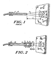
- FIG. 1 The essential elements of a prior art endophotocoagulation probe (see e.g. US-A 3 821 510 and FR-A 1 557 974 are shown in Figure 1, and include a handle or frame member 1 mounting an optical fiber 2 therein.
- Member 1 includes a rigid sheath-like probe tip surrounding the fiber 2.
- High intensity light e.g., from a laser source (not shown), is provided to a first end of the optical fiber, and emerges from the opposing end as a divergent beam 3. As shown, the angle of divergence "a" of the beam is narrow.
- the handle permits the manipulation of the fiber by a surgeon or other user so as to position its end face at a desired distance, denoted L in figure 1, from the tissue to be treated.
- the beam illuminates a target region T having a diameter D on the tissue.
- the high intensity illumination destroys tissue within the target region.
- the diameter of the region T varies directly with the distance L to the tissue.
- the power density in region T varies inversely with the square of the distance.
- the angle of divergence is different when the probe is used within a fluid medium such as vitreous humor, and when it is used in air, so the working medium is to be taken into consideration when computing the actual power reaching the tissue.
- a surgeon using such a probe is to estimate the diameter of region T and the fiber-to-tissue distance accurately, because the inverse square intensity relationship can result in undesired perforations, scarring or deep tissue damage if the probe is brought too close to the layer of tissue to be treated.
- Figure 2 is a schematic representation showing elements of a probe according to the present invention,and a representative convergent coagulation beam pattern.
- the fiber element 50 and the illuminated region T of diameter D correspond to the similar elements of Figure 1.
- the present invention also includes a focusing assembly which includes a lens 4 closely spaced from, and in optical alignment with, the output end 52 of the fiber 50 for forming a convergent output beam 5.
- Lens 4 is spaced from fiber 50 by a holder or positioner 6. As shown, the output beam 3 diverges from the end 52 of fiber 50 and strikes input face 51 of lens 4.
- the focusing assembly converts beam 3 to a convergent beam 5 of conical shape, which is emitted from output face 53 of lens 4 and converges to a narrow waist 7 at a definite distance, denoted the working distance WD, from the end of the probe.
- holder 6 is a tubular member having lens 4 centrally mounted therein. Holder 6 is coaxial with fiber 50, and is adapted for motion along the axis of the fiber so as to position lens 4 a variable distance from end face 52 thereof. Each position of lens 4 from the end of face 52 of the fiber determines a different focal position and size of waist 7 of the convergent output beam 5.
- Figure 2 shows beam 5 illuminating a region 8 of tissue. Because the plane of the tissue is not at the waist 7, region 8 is of larger diameter than the waist.
- waist 7 which is a cross section of maximum intensity, is brought into alignment with the target region of tissue.
- the waist is a well-defined "spot", which may be recognized by simple inspection of the beam. Accordingly, throughout this disclosure and in the claims, the word “spot” is used to refer to the waist of a convergent probe output beam, and also to refer to the illuminated region formed by such a beam on target tissue.
- an endophotocoagulation probe includes a lens for forming a convergent treatment beam which converges to a spot of maximum intensity at a particular distance from the probe.
- the spacing between the fiber end and the lens are adjusted to any one of several discrete selected distances to achieve selected different spot sizes at corresponding different working distances between the probe and the spot.
- a collimated or a divergent beam is produced at additional discrete fiber - lens spacings of the same instrument.
- Probe 10 includes a first tube element 12 encasing an optical fiber 14 and a second tube element 16 securing a lens 4 spaced in front of the fiber light emitting output end.
- the tube 16 forms an elongate outer body of the probe 10 and the lens 4 serves as a window closing the end of the tube 16 and forming therewith an enclosed region within which the fiber 14 and inner tube extend.
- Tube 16 may, by way of example, be thin-walled 20 gauge stainless steel tubing.
- the inner diameter of tube 12 may be up to 500 microns or more, depending on the diameter of the fiber 14 used therein.
- tube 12 extends along the fiber axis to a shank having a threaded portion 18 for positioning the tube, and a handle portion 20.
- a protective jacket 22 connects to the tube and leads the input end of fiber 14 to a high power light source, such as a gas laser.
- the outer tube 16 is mounted coaxially with the inner tube and carries at one end thereof, a lens 4 having a first or input end face 61 and a second or ouput end face 62. At the opposite end, tube 16 extends to a knob 25 with a threaded portion 24 mating with threaded portion 18 of the inner tube. Rotation of the knob 25 with respect to the handle 20 rotates the mating threaded portions, causing relative motion of the two tubes along their common axis, thereby changing the axial spacing of the lens input face 61 and the fiber output face or light emitting end 63.
- a spring-loaded stop member 26 is mounted on handle 20 and positioned under spring tension to engage indentations 27 in knob 25 so as to define particular rotational positions of handle 20 and knob 25. Each rotational position thus determines a spacing between lens 4 and fiber end face 53, so that by manually rotating knob 25, a user selects different predetermined lens spacings, hence spot sizes of the probe.
- the foregoing construction achieves an adaptable mechanical configuration for assuring that a coagulating beam has both a well-defined working distance, and, due to its fixed geometry, a spot of known power density at that distance.
- the focal length of the lens 4 is preferably selected to provide a desired smallest spot size in conjunction with a fiber spaced a selected largest distance away from its input end.
- the largest distance WD is defined by a stop which determines a maximum relative rotation of the handle and knob.
- the smallest spot size in the range then has the shortest corresponding working distance and the greatest power density. All other spots are obtained by turning the handle to decrease the separation of the output end of the fiber from the input surface of the lens. As the fiber end "zooms" toward the lens, it generates a sequence of spots of progressively increasing size, formed at progressively greater distances from the lens, and each having corresponding lower power density.
- the image of the fiber end formed by the lens occurs at the position of the smallest cross-section of the exit beam.
- all fiber to lens spacings are selected so that the output beam 3 of the fiber does not over-fill the lens, thus resulting in 100% transmission of the light power to the spot.
- the spring-loaded stop arrangement is configured to provide six different spacings of the fiber and the lens, yielding six different size spots of known dimensions, distinct working distance and relative power density.
- relative power density is meant the (constant) ratio of the power density of a spot to the power density, e.g., of the smallest spot of the series, or of the fiber end output.
- Figure 3A shows a perspective view of the probe 10 of Figure 3.
- the device comprises a handle portion 70, with a flexible connector 72 which may, for example, include a light delivery conduit.
- connector 72 may further include electrical conductors for carrying position indicating or position controlling signals.
- Handle 70 includes portions 20, 25, one of which is connected to a tubular member 16 holding the lens 40. Indentations 27 are at spaced-apart rotational positions about handle portion 25, with the spacing calculated to yield the desired spot sizes.
- FIG 10 shows a perspective view of a presently preferred embodiment of a step zoom endophotocoagulation probe 100 according to the invention.
- a thumbwheel 101 is coupled to an internal mechanism for varying the fiber-lens spacing.
- the thumbwheel itself is rotated by tangential motion directed along the axis "A" of the instrument, resulting in enhanced stability and operator control. Details of the focusing mechanism, and alternative embodiments thereof are discussed below in connection with Figures 11, 12A and 12B.
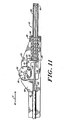
- FIG 11 shows a partial view of an embodiment of a focusing endophotocoagulation probe 100 according to the invention, which is illustrative of a presently preferred focusing design.
- Probe 100 has a handle 110 and a tip portion 112 of dimensions comparable to the probe of Figures 3, 3A and to the fixed endoprobes of the prior art.
- Probe 100 differs from the probe of Figures 3, 3A, however, in having a focusing mechanism wherein a focusing thumbwheel 101 is rotated by motion along the axis of the fiber, denoted, "A", to vary the fiber to lens spacing. Applicant has found that such axial adjustment motion provides excellent operator control while not interfering with the aiming of the beam at a target tissue.
- handle 110 secures a light conducting fiber 102 and its surrounding inner sheath 103 is a fixed position.
- An outer sheath or tube 104 (corresponding to tube 1'6 of Figure 3) holds a rod lens 105, and coaxially surrounds the fiber's sheath 103.
- Tube 104 extends through an opening 108 in the front part of handle 110, and is biased by a compression spring 109 towards a retracted position determined by a stop-defining,generally L-shaped yoke assembly 120.
- Yoke assembly 120 includes a pivoting member 121 which pivots about a pin 122 in the handle.
- a first end 123 of the yoke assembly is a yoke-like fork which fits about the inner sheath 103 and has a curved contact face 124 which presses against a thrust face 115 of the end of tube 104 to move tube 104 axially against the force of spring 109, thus varying the spacing between the tip of fiber 102 and lens 105.
- a second end 126 of the yoke assembly bears against a cam surface 117.
- Cam 117 is coaxially attached to thumbwheel 101 to pivot about a second pin 118 in the handle.
- Cam surface 117 may be a generally rounded polygonal surface with a plurality of sides each spaced at a different distance from pivot 118, so as to each define a different discrete position of yoke end 126, and thereby an axial position of tube 104.
- cam 117 may comprise a continuously varying cam surface, with particular desired spacings determined by a number of preset rotational detents 119 in the thumbwheel assembly. In use, the operator rotates thumbwheel 101 to vary the fiber to lens spacing, thereby selecting a desired spot size.
- Figures 12A, 12B show another step-position mechanism for the embodiment of Figure 10.
- This embodiment has a cam driven yoke assembly 120 like that of Figure 11, but has a fixed outer tip assembly 112.
- yoke member 121 bears against a collar 128 affixed to a rigid tube 103a holding fiber 102, and thus moves the fiber back and forth relative to a rigidly positioned lens 105 in fixed tip 112.
- the fiber 102 has a portion 102a which is not rigidly sheathed, and which is loosely suspended in a portion of the handle so that it may move slightly, as the instrument is focused, without stretching or otherwise stressing the fiber.
- a rack and pinion mechanism or a linear frictional drive may be used to provide the required displacement of tubes 103 or 104, or a combination of rotation-reducing gearing and linear displacement coupling elements may be used.
- the mounting structure may be varied to make the outer tube 104 fixedly coupled to the handle, and the inner fiber-bearing tube 103 spring mounted for motion within the handle, or vice-versa.
- a step zoom endoprobe according to the invention is fabricated as a disposable assembly with at least the handle and positioning assembly, and preferably also one or more tubes 103, 104 and other parts formed of molded plastic components.
- a device may be inexpensively produced and provided as a sterilized unit for single operation use, thus eliminating the need to disassemble and sterilize the surgical tool after each use.
- Such a single-use disposable embodiment may be implemented with a movable inner tube, as discussed above, without considering the long-term effects of fiber stress caused by movement, thus permitting the outer tube to be permanently and immovably sealed to (or formed with) the handle. This latter construction eliminates openings to the interior of the handle, such as opening 108 shown of Figure 10, enhancing the sterilization processing of the implement.
- variable positioning thumbwheel is adapted to provide, in addition to one or more convergently focused spots, a collimated or a divergent output beam, or both.
- a single instrument provides both fine focused spot sizes suitable for microsurgery upon targets near to the macula, and a collimated, or a conventional diverging beam having an effective spot size at the target of approximately one to three millimeters.
- the spot size may be varied with a fixed lens spacing by turning on or off one or more radially outer fibers.
- Such embodiments have the advantage of allowing motionless, external, electronic control of spot size during surgery with each spot formed at the same focal distance from the probe.
- the term "fiber” as used in this description and the appended claims shall be understood to include a fiber having plural distinct radially-spaced light conducting portions, or a fiber bundle having such spatial fiber distribution.
- the lens or focusing element is a positive self-focusing lens of the type sold under the SELFOC trademark.
- Such lenses are characterized in having a graded index of refraction which is rotationally symmetric about a central axis and radially variable, with highest refractive index on the axis and decreasing index toward the periphery.
- One suitable material for making such lenses is rod stock manufactured by Nippon Sheet Glass Co, Ltd., of Osaka, Japan, and is sold under their SELFOC trademark as positive GRIN rod stock.
- a GRIN rod has the useful optical characteristic of bending incident light rays in a wave-like fashion so that the light travels in a sinusoidal path with a period of oscillation P, called its pitch, which depends only on the axial refractive index and the wavelength of the light. This property permits the use of a rod segment of short axial length as the lens 4, as shown in Figure 3.
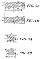
- Figure 4A shows a cross-section of a GRIN rod 30, having a central longitudinal axis 39, and traces ray paths for an object point 32 lying on end face 31 of the rod on the central axis. As shown, rays from point 32 on the axis are imaged at successive image points 32', 32" on the axis at distances P/2, P along the axis.
- Figure 4B shows an identical cross section of a GRIN rod lens 30 and a point 34 lying on end face 31 but located off the central axis of the rod.
- off-axis point 34 is imaged at image point 34' located at a distance P/2 along the axis, in inverted orientation.
- point 34 is re-imaged at point 34", in proper orientation and with unit magnification.
- distance P is called the pitch of the rod lens, and is a characteristic of the refractive index.
- Figures 5A, B show imaging properties of positive GRIN rod lenses 36, 36' of length shorter than P/2.
- Figure 5A is a schematic sectional view of a lens 36 having a length Z i ⁇ P/2 imaging an object point 38 located on its input end 31. This arrangement corresponds to lens 4 of figure 3 when there is no air separation between the end of the optic fiber 14 and the lens.
- object point 38 on the input surface of the rod lens is imaged at image point 40 located a distance Li outside of output face 33 the lens.
- Figure 5B shows another rod lens 36' of length 2 2 ⁇ P/2, used to image an object point 38' situated a distance Lo away from the input face 31 of the lens 36'.
- the length Z 2 of lens 36' can be chosen such that the image of object point 38' focuses at image point 40' located a distance L 1 from the output face 33' of the rod.
- the length of a segment of a GRIN rod one can arrange it so that the rod focuses the light originating at or near its input face into a focal region a desired working distance L i away from its output face.
- motion of the object 38' towards input face 31' results in the formed image 40' receding from the input face 33', resulting in a larger working distance.
- the length is "less than a half-pitch"
- that term includes a length that is less than a multiple of a half-pitch.
- the relevant limitation is that the rod be of such a length as to function as an optical lens.
- Figure 6 is a table identifying commonly available optical fibers suitable for conducting laser light to form spots in various size ranges when used in conjunction with a GRIN rod lens. For a given fiber, one determines the desired focal length of a GRIN rod which optimally provide the spot range indicated with minimal power transmission loss. As shown, fibers having a light transmissive core diameter, exclusive of cladding, between approximately 25 and 50 microns and a numerical aperture of approximately 0.1 may be used for a step-zoom probe covering the spot diameter range of 50 to 100 microns. At the high end, fibers having a 200 - 250 micron core diameter can be used for forming 300 - 500 micron spots.
- Three probes of different sizes each having a single such fiber as its light conductive element can cover a range of spot sizes from 50 - 500 microns, at convenient working distances and with negligible transmission losses. Those skilled in the art will understand from this description that larger or smaller spot probes may also be constructed.
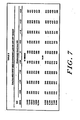
- Figure 7 shows a table of calculated cross-sections of the output beam waist of a test probe employing a 50 micron core diameter, 0.21 NA fiber using argon green 514.5 nm light and a particular GRIN rod lens, 700 microns in diameter, described more fully below.
- Design calculations were carried out to obtain spot sizes of 100, 150, 200, 250, 300 and 400 microns at the waist of the probe output beam.
- the waist for each spot size occurs at the working distance (WD) appearing in the left hand column of the table.
- Calculations were carried out for a medium containing either vitreous humor or air, to determine the spot size which would be formed on tissue if the lens were axially displaced by up to two millimeters in either direction from the nominal focal position WD.
- the spot size remains constant independently of whether air or vitreous humor is the interstitial medium; only the working distance shifts due to the steeper convergence angle of the output beam when light refracts at the lens/air interface.
- Figures 8 A and B show the normalized variation of spot diameter in air and in vitreous, respectively, when the probe is in a defocused position. These Figures graphically illustrate the functional dependence of spot dispersion upon axial motion of the probe.
- spot sizes e.g., below 250 microns
- the variation in spot diameter with axial motion of the probe is so pronounced that it essentially eliminates the possibility of damage to tissue away from the focal region.
- dropoff of the power density in defocused positions is achieved.
- a surgeon may position the probe at the correct working distance by visual inspection. The surgeon need only move it slightly back and forth, using low power illumination, and observe the consequent spot expansion and contraction until the correct working distance is obtained.
- the greater dropoff characteristics correspond to a highly convergent pattern which allows precise visual determination of proper placement of the probe at the required working distance. This capability reduces dosage errors caused by incorrect positioning.
- fiber 14 was a quartz fiber having a 50 micron core diameter, 0.21 NA and an index of refraction of approximately 1.46.
- the output beam from such a fiber diverges in the air-filled fiber/lens interspace at an angle of approximately 12 ° from the fiber axis.
- Lens 4 was a segment of positive GRIN rod identified by its manufacturer, Nippon Sheet Glass Co, Ltd., as the ISLW series.
- Lens 4 had a diameter of 700 microns, was a quartz rod enriched by surface diffusion so as to achieve a refractive index tapering from 1.648 at its core to 1.610 at its periphery.
- Lens 4 was formed of rod stock mounted in a 20 gauge stainless steel tube.
- Stops in the threaded handle were arranged to provide positive detents at fiber-lens spacings of 1.354, 1.172, 1.080, 1.026, 0.989, and 0.942 millimeters, resulting in spot sizes of 100, 150, 200, 250, 300, and 400 microns, respectively.
- the corresponding working distances varying from approximately 3 to approximately 10 millimeters in air and vitreous, are set forth in the left hand column of table 2, Figure 7.
- an electronic micropositioning motor such as a stepping motor, connected to a screw or to a linear drive, may be provided for varying the spacing of the fiber and the lens.
- Figure 9 shows a schematic representation of such an embodiment 90 having a tip portion 91 containing a light conduit or fiber element and a lens relatively movable with respect to the fiber, and also having a positioner 92 included a handle structure with means for controllably moving the lens and/or fiber.
- a control unit 93 receives signals, which may be indicative of motor movement or handle position, along lines 94, 95 as control signals.
- Unit 93 may include a microprocessor to monitor or control the focus and the spot intensity of the probe.
- User-activated switches in the handle may provide selection signals over line 95 indicative of selected spot size.
- Line 94 carries control signals to the positioner, and may also carry position-indicating signals to the control unit. Responsive to selection signals on line 95, or position indicating signals on line 94, control unit 93 provides signals over line 96 to light source 97 to control the intensity of and/or to trigger the source.
- the control means may be configured, e.g., to achieve constant power density independently of selected spot size.
- the handle portion 92 of the probe may include hand activated switches to provide signals indicative of the chosen spot size. Such signals are then sensed by the control unit to select the level of laser power supplied to the fiber, and to control the positioner so as to achieve a desired spot size and intensity.
- the control unit may also, responsive to a hand-switched signal on lines 94, 95, activate a low-power light source to permit the surgeon to visualize the output beam for positioning the probe at its working distance from the target tissue.
- a "focus" button may be provided on the handle for this purpose, as well as a "trigger” button.
Description
- The present invention relates to a probe such as used for the surgical treatment of localized tissue areas by the application of high intensity light energy thereto. The invention also relates to endophoto- coagulating probes, such as used for intraocular photocoagulation which may, for example, be performed at the time of pars planar vitrectomy.
- Presently, known endophotocoagulation probes available to a surgeon have an optical system consisting essentially of a single quartz fiber of a selected diameter having a polished end. The fiber is encased in a thin, needle-like tube which is inserted into the eyeball through an incision in the cornea in order to treat tissue located, for example, at the eye fundus. High power light energy is applied at one end of the fiber and the other end delivers a divergent ouput beam. A surgeon using such a probe must estimate the beam diameter as projected onto the tissue, which depends on the divergence angle of the beam and on the distance between the fiber end and the target tissue. Since the divergence angle varies depending on the surrounding medium, the delivered power density at the target site is greater when the beam travels through a fluid filled cavity than through air.
- Destruction of tissue occurs in the region of tissue illuminated by the beam. This illuminated region is referred to generally herein as the "spot" of the probe. Because the size of the illuminated region depends both on the surrounding medium and on the distance from the fiber to the treated tissue, the actual dosage delivered by a prior art endophotocoagulator is a matter of considerable variation, and requires estimation of these parameters by the surgeon. Thus, it is desirable to provide an endophotocoagulation probe having a beam which forms a well-defined spot.
- It is therefore an object of the invention to provide a photocoagulation probe having definite and known spot size and light intensity distribution.
- The invention seeks to provide a photocoagulation probe having a distinctive output beam pattern for aiding the operator in positioning the probe, and to provide a photocoagulation probe having a spot size independent of the surrounding medium.
- The invention has also sought to provide a photocoagulation probe having plural, operator-selectable beam sizes or patterns.
- These and other desired features are achieved in an endophotocoagulation probe having an optic fiber for channelling light, and a lens for focusing the light from the end of the fiber onto target tissue.
- According to the present invention, there is provided an endophotocoagulation probe for the application of light energy of a desired power to a target region of tissue within the eye of a subject, wherein the probe comprises: a handle a probe tip having an elongate hollow and substantially rigid outer body carried by said handle and extending from said handle to a distal light output end, the outer body having a diameter and a length appropriate for insertion into the eye and for manipulation therein by the handle, a graded index lens included in the light output end of the probe tip and constituting a light transmissive window closing the outer body and providing therewith an enclosed region, the graded index lens having a first end face facing outwardly of the enclosed region and defining an extreme extension of the probe tip and a second end face facing inwardly and defining an end wall of the enclosed region, and a light conducting fiber extending within the enclosed region to a light emitting fiber end, the graded index lens being positioned at a desired spacing from the light emitting fibre end (a) to receive substantially all of a divergent beam of light exiting the light emitting fiber end and (b) to form convergent output beam having the desired power in a focal region spaced from the lens first end face for treating tissue within the eye.
- Preferably the lens is a GRIN lens formed of a segment of a rod having a graded index of refraction. The lens forms a convergent beam with the waist of the beam providing a spot of maximum power density at a defined working distance. In one preferred embodiment a positioner which varies the spacing between the lens and the fiber to vary the spot size includes a step positioning handle which selectively adjusts the spacing to one of a plurality of discrete spacings, so as to achieve a plurality of different spot sizes, each having a known power density. In one such embodiment, a single probe can provide six operator-selectable spot sizes within a range from approximately 100 to 400 microns. Probes using preferred fiber and selfocal lens elements and having spot sizes from below 50 to above 500 microns allow precise treatment of tissue targets of arbitrary dimensions.
- The invention will now be explained in more detail by way of example only and by reference to the accompanying drawings, in which:
- Figure 1 is a schematic representation of a prior art endophotocoagulator and its beam pattern;
- Figure 2 is a schematic representation showing elements of a probe according to the invention and an illustrative coagulation beam pattern;
- Figure 3 is a schematic cross section along the axis of one embodiment of a step-zoom probe according to the invention;
- Figure 3A is a perspective view of the device of Figure 3.
- Figures 4A, B and 5A, B illustrate optical properties of the GRIN rod lens of a preferred embodiment;
- Figure 6 is a table of optical fiber elements suitable for probes with different spot diameters;
- Figure 7 is a table of calculated cross sections of a beam of one embodiment of the invention in focused and defocused positions;
- Figures 8A, B show the normalized variations of spot diameter for the probe of Figure 7;
- Figure 9 is a block diagram of a probe and control system according to the invention;
- Figure 10 shows a perspective view of a presently preferred prototype instrument according to the invention;
- Figure 11 shows a cutaway side view of an embodiment similar to that of Figure 10 with a preferred focusing assembly; and
- Figures 12A, 12B show views of a related embodiment with such a focussing assembly.
- An endophotocoagulation probe is a non-contact surgical instrument used within the eye for projecting a beam of intense light energy to destroy tissue in a relatively local area, e.g. an area having a cross section of a millimeter or less, which may for example be vascular tissue in the retina.
- Such a probe is distinguished, for example, from a cauterization probe having a light output face which is brought into direct contact with the tissue to be destroyed. An endophotocoagulation probe operates at a distance from the target tissue, and applies light energy thereto at a power sufficient to cause local tissue destruction by coagulation or the like.
- The essential elements of a prior art endophotocoagulation probe (see e.g. US-A 3 821 510 and FR-
A 1 557 974 are shown in Figure 1, and include a handle orframe member 1 mounting anoptical fiber 2 therein.Member 1 includes a rigid sheath-like probe tip surrounding thefiber 2. High intensity light, e.g., from a laser source (not shown), is provided to a first end of the optical fiber, and emerges from the opposing end as a divergent beam 3. As shown, the angle of divergence "a" of the beam is narrow. The handle permits the manipulation of the fiber by a surgeon or other user so as to position its end face at a desired distance, denoted L in figure 1, from the tissue to be treated. The beam illuminates a target region T having a diameter D on the tissue. The high intensity illumination destroys tissue within the target region. - Because the output beam is divergent, the diameter of the region T varies directly with the distance L to the tissue. The power density in region T varies inversely with the square of the distance. The angle of divergence is different when the probe is used within a fluid medium such as vitreous humor, and when it is used in air, so the working medium is to be taken into consideration when computing the actual power reaching the tissue. Ideally, a surgeon using such a probe is to estimate the diameter of region T and the fiber-to-tissue distance accurately, because the inverse square intensity relationship can result in undesired perforations, scarring or deep tissue damage if the probe is brought too close to the layer of tissue to be treated. Working with a hand-held probe at millimeter or submillimeter range, these parameters are difficult to estimate, and instances of inadvertent tissue damage have been reported in the literature. Despite these shortcomings, the development of a simple ranging or optical positioning system for such a probe has proven elusive. This may be in part because the diameter of the fiber and holder, which for an ophthalmic probe may together amount to under one millimeter, precludes or discourages inclusion of conventional optical elements for ranging, positioning, or beam-collimating.
- Figure 2 is a schematic representation showing elements of a probe according to the present invention,and a representative convergent coagulation beam pattern. The
fiber element 50 and the illuminated region T of diameter D correspond to the similar elements of Figure 1. The present invention, however, also includes a focusing assembly which includes alens 4 closely spaced from, and in optical alignment with, theoutput end 52 of thefiber 50 for forming a convergent output beam 5.Lens 4 is spaced fromfiber 50 by a holder or positioner 6. As shown, the output beam 3 diverges from theend 52 offiber 50 and strikesinput face 51 oflens 4. The focusing assembly converts beam 3 to a convergent beam 5 of conical shape, which is emitted from output face 53 oflens 4 and converges to a narrow waist 7 at a definite distance, denoted the working distance WD, from the end of the probe. In the schematic representation of Figure 2, holder 6 is a tubularmember having lens 4 centrally mounted therein. Holder 6 is coaxial withfiber 50, and is adapted for motion along the axis of the fiber so as to position lens 4 a variable distance fromend face 52 thereof. Each position oflens 4 from the end offace 52 of the fiber determines a different focal position and size of waist 7 of the convergent output beam 5. Figure 2 shows beam 5 illuminating a region 8 of tissue. Because the plane of the tissue is not at the waist 7, region 8 is of larger diameter than the waist. - In accordance with the invention, waist 7, which is a cross section of maximum intensity, is brought into alignment with the target region of tissue. The waist is a well-defined "spot", which may be recognized by simple inspection of the beam. Accordingly, throughout this disclosure and in the claims, the word "spot" is used to refer to the waist of a convergent probe output beam, and also to refer to the illuminated region formed by such a beam on target tissue.
- Thus, an endophotocoagulation probe according to the present invention includes a lens for forming a convergent treatment beam which converges to a spot of maximum intensity at a particular distance from the probe. According to a further embodiment, the spacing between the fiber end and the lens are adjusted to any one of several discrete selected distances to achieve selected different spot sizes at corresponding different working distances between the probe and the spot. According to a further embodiment, a collimated or a divergent beam is produced at additional discrete fiber - lens spacings of the same instrument.
- One prototype embodiment 10 of such a probe is shown in Figures 3, 3A. This embodiment is referred to herein as a step-zoom probe. Figure 3 shows a schematic cross-section along the
central axis 54 of the probe. Probe 10 includes a first tube element 12 encasing an optical fiber 14 and asecond tube element 16 securing alens 4 spaced in front of the fiber light emitting output end. Thetube 16 forms an elongate outer body of the probe 10 and thelens 4 serves as a window closing the end of thetube 16 and forming therewith an enclosed region within which the fiber 14 and inner tube extend.Tube 16 may, by way of example, be thin-walled 20 gauge stainless steel tubing. The inner diameter of tube 12 may be up to 500 microns or more, depending on the diameter of the fiber 14 used therein. In this embodiment, tube 12 extends along the fiber axis to a shank having a threaded portion 18 for positioning the tube, and ahandle portion 20. At an outer end of thehandle portion 20, a protective jacket 22 connects to the tube and leads the input end of fiber 14 to a high power light source, such as a gas laser. - The
outer tube 16 is mounted coaxially with the inner tube and carries at one end thereof, alens 4 having a first or input end face 61 and a second orouput end face 62. At the opposite end,tube 16 extends to aknob 25 with a threadedportion 24 mating with threaded portion 18 of the inner tube. Rotation of theknob 25 with respect to thehandle 20 rotates the mating threaded portions, causing relative motion of the two tubes along their common axis, thereby changing the axial spacing of the lens input face 61 and the fiber output face orlight emitting end 63. A spring-loadedstop member 26 is mounted onhandle 20 and positioned under spring tension to engageindentations 27 inknob 25 so as to define particular rotational positions ofhandle 20 andknob 25. Each rotational position thus determines a spacing betweenlens 4 and fiber end face 53, so that by manually rotatingknob 25, a user selects different predetermined lens spacings, hence spot sizes of the probe. - The foregoing construction achieves an adaptable mechanical configuration for assuring that a coagulating beam has both a well-defined working distance, and, due to its fixed geometry, a spot of known power density at that distance.
- The focal length of the
lens 4 is preferably selected to provide a desired smallest spot size in conjunction with a fiber spaced a selected largest distance away from its input end. The largest distance WD is defined by a stop which determines a maximum relative rotation of the handle and knob. The smallest spot size in the range then has the shortest corresponding working distance and the greatest power density. All other spots are obtained by turning the handle to decrease the separation of the output end of the fiber from the input surface of the lens. As the fiber end "zooms" toward the lens, it generates a sequence of spots of progressively increasing size, formed at progressively greater distances from the lens, and each having corresponding lower power density. For each fiber to lens spacing, the image of the fiber end formed by the lens occurs at the position of the smallest cross-section of the exit beam. Preferably, all fiber to lens spacings are selected so that the output beam 3 of the fiber does not over-fill the lens, thus resulting in 100% transmission of the light power to the spot. - In the preferred step-zoom probe shown in Figure 3, the spring-loaded stop arrangement is configured to provide six different spacings of the fiber and the lens, yielding six different size spots of known dimensions, distinct working distance and relative power density. By relative power density is meant the (constant) ratio of the power density of a spot to the power density, e.g., of the smallest spot of the series, or of the fiber end output.
- Figure 3A shows a perspective view of the probe 10 of Figure 3. As shown, the device comprises a
handle portion 70, with aflexible connector 72 which may, for example, include a light delivery conduit. For alternative embodiments discussed below,connector 72 may further include electrical conductors for carrying position indicating or position controlling signals.Handle 70 includesportions tubular member 16 holding thelens 40.Indentations 27 are at spaced-apart rotational positions abouthandle portion 25, with the spacing calculated to yield the desired spot sizes. - Figure 10 shows a perspective view of a presently preferred embodiment of a step
zoom endophotocoagulation probe 100 according to the invention. In this embodiment, athumbwheel 101 is coupled to an internal mechanism for varying the fiber-lens spacing. The thumbwheel itself is rotated by tangential motion directed along the axis "A" of the instrument, resulting in enhanced stability and operator control. Details of the focusing mechanism, and alternative embodiments thereof are discussed below in connection with Figures 11, 12A and 12B. - Figure 11 shows a partial view of an embodiment of a focusing
endophotocoagulation probe 100 according to the invention, which is illustrative of a presently preferred focusing design.Probe 100 has ahandle 110 and atip portion 112 of dimensions comparable to the probe of Figures 3, 3A and to the fixed endoprobes of the prior art.Probe 100 differs from the probe of Figures 3, 3A, however, in having a focusing mechanism wherein a focusingthumbwheel 101 is rotated by motion along the axis of the fiber, denoted, "A", to vary the fiber to lens spacing. Applicant has found that such axial adjustment motion provides excellent operator control while not interfering with the aiming of the beam at a target tissue. - As shown in Figure 11, handle 110 secures a
light conducting fiber 102 and its surroundinginner sheath 103 is a fixed position. An outer sheath or tube 104 (corresponding to tube 1'6 of Figure 3) holds arod lens 105, and coaxially surrounds the fiber'ssheath 103.Tube 104 extends through anopening 108 in the front part ofhandle 110, and is biased by acompression spring 109 towards a retracted position determined by a stop-defining,generally L-shapedyoke assembly 120. -
Yoke assembly 120 includes a pivotingmember 121 which pivots about apin 122 in the handle. Afirst end 123 of the yoke assembly is a yoke-like fork which fits about theinner sheath 103 and has acurved contact face 124 which presses against athrust face 115 of the end oftube 104 to movetube 104 axially against the force ofspring 109, thus varying the spacing between the tip offiber 102 andlens 105. Asecond end 126 of the yoke assembly bears against a cam surface 117. Cam 117 is coaxially attached tothumbwheel 101 to pivot about a second pin 118 in the handle. Cam surface 117 may be a generally rounded polygonal surface with a plurality of sides each spaced at a different distance from pivot 118, so as to each define a different discrete position ofyoke end 126, and thereby an axial position oftube 104. Alternatively, cam 117 may comprise a continuously varying cam surface, with particular desired spacings determined by a number of presetrotational detents 119 in the thumbwheel assembly. In use, the operator rotatesthumbwheel 101 to vary the fiber to lens spacing, thereby selecting a desired spot size. - Figures 12A, 12B show another step-position mechanism for the embodiment of Figure 10. This embodiment has a cam driven
yoke assembly 120 like that of Figure 11, but has a fixedouter tip assembly 112. In the embodiment of Figures 12A, 12B, however,yoke member 121 bears against acollar 128 affixed to arigid tube 103a holdingfiber 102, and thus moves the fiber back and forth relative to a rigidly positionedlens 105 in fixedtip 112. As best seen in Figure 12A, thefiber 102 has a portion 102a which is not rigidly sheathed, and which is loosely suspended in a portion of the handle so that it may move slightly, as the instrument is focused, without stretching or otherwise stressing the fiber. - In related embodiments, other mechanisms for positioning the lens may be used. For example, a rack and pinion mechanism, or a linear frictional drive may be used to provide the required displacement of
tubes outer tube 104 fixedly coupled to the handle, and the inner fiber-bearingtube 103 spring mounted for motion within the handle, or vice-versa. - In a further preferred embodiment, a step zoom endoprobe according to the invention is fabricated as a disposable assembly with at least the handle and positioning assembly, and preferably also one or
more tubes opening 108 shown of Figure 10, enhancing the sterilization processing of the implement. - In the discussion of embodiments above, frequent reference is made to a fiber-to-lens spacing for providing a convergently focused spot which is an image of the fiber output end. It is also possible with applicant's structure to provide a stop which defines an axial position of the fiber end at the lens focal point, or at a postion closer to the lens than its focal point. These two fiber-lens spacings yield a collimated or a divergent output beam, respectively. In contrast to the sub-millimeter displacement for providing convergent step-zoom spots, somewhat larger total displacement is necessary to include a collimated or a divergent beam forming spacing. In further embodiments of a probe according to the invention, the variable positioning thumbwheel is adapted to provide, in addition to one or more convergently focused spots, a collimated or a divergent output beam, or both. In this manner, a single instrument provides both fine focused spot sizes suitable for microsurgery upon targets near to the macula, and a collimated, or a conventional diverging beam having an effective spot size at the target of approximately one to three millimeters.
- In further embodiments of the invention, it is envisaged that by replacing the
single fiber 102 with a fiber bundle, or with a specially fabricated coaxially mounted fiber, having inner and outer light conducting regions, the spot size may be varied with a fixed lens spacing by turning on or off one or more radially outer fibers. Such embodiments have the advantage of allowing motionless, external, electronic control of spot size during surgery with each spot formed at the same focal distance from the probe. For such embodiments, the term "fiber" as used in this description and the appended claims, shall be understood to include a fiber having plural distinct radially-spaced light conducting portions, or a fiber bundle having such spatial fiber distribution. - Various design considerations and technical details are set forth below, illustrating the performance range of an endoprobe constructed according to the invention.
- According to the illustrated prototype embodiments of the invention, the lens or focusing element is a positive self-focusing lens of the type sold under the SELFOC trademark. Such lenses are characterized in having a graded index of refraction which is rotationally symmetric about a central axis and radially variable, with highest refractive index on the axis and decreasing index toward the periphery. One suitable material for making such lenses is rod stock manufactured by Nippon Sheet Glass Co, Ltd., of Osaka, Japan, and is sold under their SELFOC trademark as positive GRIN rod stock. A GRIN rod has the useful optical characteristic of bending incident light rays in a wave-like fashion so that the light travels in a sinusoidal path with a period of oscillation P, called its pitch, which depends only on the axial refractive index and the wavelength of the light. This property permits the use of a rod segment of short axial length as the
lens 4, as shown in Figure 3. - Several dimensional and optical design factors related to the use of such a lens in the present invention will be understood with reference to Figures 4A, 4B, 5A and 5B. Figure 4A shows a cross-section of a
GRIN rod 30, having a central longitudinal axis 39, and traces ray paths for anobject point 32 lying onend face 31 of the rod on the central axis. As shown, rays frompoint 32 on the axis are imaged at successive image points 32', 32" on the axis at distances P/2, P along the axis. - Figure 4B shows an identical cross section of a
GRIN rod lens 30 and apoint 34 lying onend face 31 but located off the central axis of the rod. As shown, off-axis point 34 is imaged at image point 34' located at a distance P/2 along the axis, in inverted orientation. At distance P,point 34 is re-imaged atpoint 34", in proper orientation and with unit magnification. As noted above, distance P is called the pitch of the rod lens, and is a characteristic of the refractive index. According to the preferred embodiment of the invention, as shown in figure 3, a segment of a positive GRIN rod having a length lying between (nP/2) and ((n+1)P/2)., where n is a small integer, serves as a lens element for focusing light. - Figures 5A, B show imaging properties of positive
GRIN rod lenses 36, 36' of length shorter than P/2. Figure 5A is a schematic sectional view of alens 36 having a length Zi < P/2 imaging anobject point 38 located on itsinput end 31. This arrangement corresponds tolens 4 of figure 3 when there is no air separation between the end of the optic fiber 14 and the lens. In this case,object point 38 on the input surface of the rod lens is imaged atimage point 40 located a distance Li outside of output face 33 the lens. Figure 5B shows another rod lens 36' oflength 22 < P/2, used to image an object point 38' situated a distance Lo away from theinput face 31 of the lens 36'. This situation corresponds to the fiber/lens arrangement of figure 3 with the fiber end separated from the lens by a distance Lo. In this case, the length Z2 of lens 36' can be chosen such that the image of object point 38' focuses at image point 40' located a distance L1 from the output face 33' of the rod. Thus, by suitably choosing the length of a segment of a GRIN rod, one can arrange it so that the rod focuses the light originating at or near its input face into a focal region a desired working distance Li away from its output face. As with a conventional lens, motion of the object 38' towards input face 31' results in the formed image 40' receding from the input face 33', resulting in a larger working distance. - It will be understood that although the foregoing discussion relates to Figures 5A,B showing a lens of length Z (that is, Zi or Z2) shorter than P/2, a lens of length (Z+nP/2) for (n) an integer, will also focus the image a distance Li from it output face. The image will be inverted for (n) even, and will suffer progressive but moderate transmission loss for increasing (n). For ease of handling, it may be desirable to use GRIN rod lenses of length Z, (Z+P/2), (Z+P) or other low integral increment of (P/2). Accordingly, when it is specified herein and in the claims that the length is "less than a half-pitch", that term includes a length that is less than a multiple of a half-pitch. The relevant limitation is that the rod be of such a length as to function as an optical lens.
- It has been found that the foregoing focusing property of positive GRIN rods is well suited for their use as lens elements to achieve a spot of determined size and focal position in an endophotocoagulation probe. Various details related to their use in probes such as the embodiment shown in the figures will now be discussed by way of illustration.
- Figure 6 is a table identifying commonly available optical fibers suitable for conducting laser light to form spots in various size ranges when used in conjunction with a GRIN rod lens. For a given fiber, one determines the desired focal length of a GRIN rod which optimally provide the spot range indicated with minimal power transmission loss. As shown, fibers having a light transmissive core diameter, exclusive of cladding, between approximately 25 and 50 microns and a numerical aperture of approximately 0.1 may be used for a step-zoom probe covering the spot diameter range of 50 to 100 microns. At the high end, fibers having a 200 - 250 micron core diameter can be used for forming 300 - 500 micron spots. Three probes of different sizes each having a single such fiber as its light conductive element can cover a range of spot sizes from 50 - 500 microns, at convenient working distances and with negligible transmission losses. Those skilled in the art will understand from this description that larger or smaller spot probes may also be constructed.
- Figure 7 shows a table of calculated cross-sections of the output beam waist of a test probe employing a 50 micron core diameter, 0.21 NA fiber using argon green 514.5 nm light and a particular GRIN rod lens, 700 microns in diameter, described more fully below. Design calculations were carried out to obtain spot sizes of 100, 150, 200, 250, 300 and 400 microns at the waist of the probe output beam. The waist for each spot size occurs at the working distance (WD) appearing in the left hand column of the table. Calculations were carried out for a medium containing either vitreous humor or air, to determine the spot size which would be formed on tissue if the lens were axially displaced by up to two millimeters in either direction from the nominal focal position WD. As noted above, the spot size remains constant independently of whether air or vitreous humor is the interstitial medium; only the working distance shifts due to the steeper convergence angle of the output beam when light refracts at the lens/air interface.
- Of particular note in Figure 7 is the extreme dependence of spot size on axial position for the smaller spot sizes. Thus, for example, with a 100 micron "spot" or focal waist of the convergent beam, a translation of the probe by one millimeter along the axis results in spot broadening in vitreous by a factor of 3.21 (in the minus direction) to 4.42 (in the positive direction), and between 2.66 and 3.57 in air. Since the spot power density is inversely proportional to the square of these factors, it can be seen that the illuminating power quickly drops to a level of 10% or less when a probe is in a defocused position. Similar but less extreme effects hold for the larger diameter spot sizes.
- Figures 8 A and B show the normalized variation of spot diameter in air and in vitreous, respectively, when the probe is in a defocused position. These Figures graphically illustrate the functional dependence of spot dispersion upon axial motion of the probe. In particular, with the smaller spot sizes (e.g., below 250 microns) the variation in spot diameter with axial motion of the probe is so pronounced that it essentially eliminates the possibility of damage to tissue away from the focal region. Even with larger spot sizes, dropoff of the power density in defocused positions is achieved. Also, using a probe having such a beam pattern, a surgeon may position the probe at the correct working distance by visual inspection. The surgeon need only move it slightly back and forth, using low power illumination, and observe the consequent spot expansion and contraction until the correct working distance is obtained. Thus, the greater dropoff characteristics correspond to a highly convergent pattern which allows precise visual determination of proper placement of the probe at the required working distance. This capability reduces dosage errors caused by incorrect positioning.
- Dimensions and technical properties of elements of one representative probe will now be described in detail by way of example. Other examples for probes having a different range of spot sizes may readily be calculated by a person skilled in the art.
- In the illustrative embodiments of Figure 10 and Figures 3, 3A, fiber 14 was a quartz fiber having a 50 micron core diameter, 0.21 NA and an index of refraction of approximately 1.46. The output beam from such a fiber diverges in the air-filled fiber/lens interspace at an angle of approximately 12° from the fiber axis.
Lens 4 was a segment of positive GRIN rod identified by its manufacturer, Nippon Sheet Glass Co, Ltd., as the ISLW series.Lens 4 had a diameter of 700 microns, was a quartz rod enriched by surface diffusion so as to achieve a refractive index tapering from 1.648 at its core to 1.610 at its periphery.Lens 4 was formed of rod stock mounted in a 20 gauge stainless steel tube. It had a nominal pitch of 7.7mm for 514.5 nm light, and was cut in a segment approximately 4.72mm long. this intermediate length, greater that a half-pitch and less than a full pitch length, was chosen for ease of handling. The smallest spot was a 100 micron spot, and was achieved by positioning the output end of fiber 14 a distance of 1.354 millimeters from the input face of the lens. With this geometry, a working distance of 3 millimeters between the output beam waist and the output face of the lens was obtained. Stops in the threaded handle were arranged to provide positive detents at fiber-lens spacings of 1.354, 1.172, 1.080, 1.026, 0.989, and 0.942 millimeters, resulting in spot sizes of 100, 150, 200, 250, 300, and 400 microns, respectively. The corresponding working distances, varying from approximately 3 to approximately 10 millimeters in air and vitreous, are set forth in the left hand column of table 2, Figure 7. - It will be apparent that the mechanical structure of the step-zoom probe has been described by way of illustration only. Rather than the hand-moved threaded collar with a detent structure illustrated in Figures 3, 3A, an electronic micropositioning motor, such as a stepping motor, connected to a screw or to a linear drive, may be provided for varying the spacing of the fiber and the lens.
- Figure 9 shows a schematic representation of such an embodiment 90 having a
tip portion 91 containing a light conduit or fiber element and a lens relatively movable with respect to the fiber, and also having a positioner 92 included a handle structure with means for controllably moving the lens and/or fiber. Acontrol unit 93 receives signals, which may be indicative of motor movement or handle position, alonglines Unit 93 may include a microprocessor to monitor or control the focus and the spot intensity of the probe. User-activated switches in the handle may provide selection signals overline 95 indicative of selected spot size.Line 94 carries control signals to the positioner, and may also carry position-indicating signals to the control unit. Responsive to selection signals online 95, or position indicating signals online 94,control unit 93 provides signals overline 96 to lightsource 97 to control the intensity of and/or to trigger the source. - The control means may be configured, e.g., to achieve constant power density independently of selected spot size. Alternatively, the handle portion 92 of the probe may include hand activated switches to provide signals indicative of the chosen spot size. Such signals are then sensed by the control unit to select the level of laser power supplied to the fiber, and to control the positioner so as to achieve a desired spot size and intensity. The control unit may also, responsive to a hand-switched signal on
lines
Claims (12)
a probe tip (e.g. 16, 112) having an elongate hollow and substantially rigid outer body (16) carried by said handle and extending from said handle to a distal light output end, the outer body (16) having a diameter and a length appropriate for insertion into the eye and for manipulation therein by the handle, a graded index lens (4) included in the light output end of the probe tip and constituting a light transmissive window closing the outer body (16) and providing therewith an enclosed region, the graded index lens (4) having a first end face (62) facing outwardly of the enclosed region and defining an extreme extension of the probe tip and a second end face (61) facing inwardly and defining an end wall of the enclosed region, and a light conducting fiber (2, 50, 102) extending within the enclosed region to a light emitting fiber end (52, 63), the graded index lens (4) being positioned at a desired spacing from the light emitting fiber end (a) to receive substantially all of a divergent beam of light exiting the light emitting fiber end (63) and (b) to form a convergent output beam (5) having the desired power in a focal region spaced from the lens first end face (62) for treating tissue within the eye.
Priority Applications (1)
| Application Number | Priority Date | Filing Date | Title |
|---|---|---|---|
| AT87303605T ATE58998T1 (en) | 1986-04-24 | 1987-04-24 | DEVICE FOR ENDOPHOTOCOAGULATION. |
Applications Claiming Priority (4)
| Application Number | Priority Date | Filing Date | Title |
|---|---|---|---|
| US85604586A | 1986-04-24 | 1986-04-24 | |
| US856045 | 1986-04-24 | ||
| US36959 | 1987-04-16 | ||
| US07/036,959 US4865029A (en) | 1986-04-24 | 1987-04-16 | Endophotocoagulation probe |
Publications (2)
| Publication Number | Publication Date |
|---|---|
| EP0248520A1 EP0248520A1 (en) | 1987-12-09 |
| EP0248520B1 true EP0248520B1 (en) | 1990-12-12 |
Family
ID=26713662
Family Applications (1)
| Application Number | Title | Priority Date | Filing Date |
|---|---|---|---|
| EP87303605A Expired EP0248520B1 (en) | 1986-04-24 | 1987-04-24 | Endophotocoagulation probe |
Country Status (3)
| Country | Link |
|---|---|
| US (1) | US4865029A (en) |
| EP (1) | EP0248520B1 (en) |
| DE (1) | DE3766653D1 (en) |
Cited By (1)
| Publication number | Priority date | Publication date | Assignee | Title |
|---|---|---|---|---|
| DE19920615A1 (en) * | 1999-05-05 | 2000-12-07 | Tui Laser Ag | Device for treating glaucorn of the eye |
Families Citing this family (91)
| Publication number | Priority date | Publication date | Assignee | Title |
|---|---|---|---|---|
| JPH03502288A (en) * | 1988-01-25 | 1991-05-30 | リフラクティヴ レーザー リサーチ アンド ディヴェロプメント インコーポレイテッド | Laser surgery method and device |
| US5037421A (en) * | 1989-10-06 | 1991-08-06 | Coherent, Inc., Medical Group | Mid-infrared laser arthroscopic procedure |
| US5147354B1 (en) * | 1988-08-19 | 1997-10-14 | Coherent Inc | Mid-infrared laser endoscope |
| US5147349A (en) * | 1988-10-07 | 1992-09-15 | Spectra-Physics, Inc. | Diode laser device for photocoagulation of the retina |
| US5222952A (en) * | 1988-10-28 | 1993-06-29 | Hanspeter Loertscher | Method for laser sclerostomy |
| EP0368512A3 (en) * | 1988-11-10 | 1990-08-08 | Premier Laser Systems, Inc. | Multiwavelength medical laser system |
| US5207673A (en) * | 1989-06-09 | 1993-05-04 | Premier Laser Systems, Inc. | Fiber optic apparatus for use with medical lasers |
| US5129896A (en) * | 1989-11-13 | 1992-07-14 | Hasson Harrith M | Holder to facilitate use of a laser in surgical procedures |
| JPH10511005A (en) | 1990-01-08 | 1998-10-27 | ヘルス リサーチ インコーポレイテッド | Submersible lens fiber optic assembly |
| WO1992007624A1 (en) * | 1990-10-25 | 1992-05-14 | Coherent, Inc. | Delivery probe for a diode laser endophotocoagulator |
| AU645851B2 (en) * | 1991-02-04 | 1994-01-27 | Citation Medical Corporation | Portable arthroscope with disposable probe |
| US5163935A (en) * | 1991-02-20 | 1992-11-17 | Reliant Laser Corporation | Surgical laser endoscopic focusing guide with an optical fiber link |
| US5351678A (en) * | 1992-09-01 | 1994-10-04 | Citation Medical Corporation | Endoscope scope assembly for full hemisphere view |
| US5688264A (en) * | 1992-10-19 | 1997-11-18 | The University Of Miami | Laser treatment for retinal detachment |
| US5413555A (en) * | 1993-04-30 | 1995-05-09 | Mcmahan; William H. | Laser delivery system |
| US5441041A (en) * | 1993-09-13 | 1995-08-15 | United States Surgical Corporation | Optical trocar |
| US5467762A (en) * | 1993-09-13 | 1995-11-21 | United States Surgical Corporation | Optical trocar |
| US5478338A (en) * | 1993-09-24 | 1995-12-26 | Reynard; Michael | Fiber optic sleeve for surgical instruments |
| USRE36473E (en) * | 1994-05-12 | 1999-12-28 | Indigo Medical, Inc. | Fiberoptic delivery system and method of use |
| US5469524A (en) * | 1994-05-12 | 1995-11-21 | Indigo Medical, Incorporated | Fiberoptic delivery system and method of use |
| CA2149290C (en) * | 1994-05-26 | 2006-07-18 | Carl T. Urban | Optical trocar |
| US5599341A (en) * | 1994-06-15 | 1997-02-04 | Keravision, Inc. | Laser surgical procedure and device for treatment of the cornea |
| US5738676A (en) * | 1995-01-03 | 1998-04-14 | Hammer; Daniel X. | Laser surgical probe for use in intraocular surgery |
| WO1996032895A2 (en) * | 1995-04-17 | 1996-10-24 | Coherent, Inc. | Method and apparatus for manipulating, cutting, ablating and coagulating targeted tissue within a patient |
| US7655002B2 (en) | 1996-03-21 | 2010-02-02 | Second Sight Laser Technologies, Inc. | Lenticular refractive surgery of presbyopia, other refractive errors, and cataract retardation |
| DE19710797C1 (en) * | 1997-03-17 | 1998-10-08 | Peter Dr Zierden | Localised body heating instrument for moxibustion-type treatment |
| US6120498A (en) * | 1998-03-05 | 2000-09-19 | Jani; Mahendra G. | Aspirating handpieces for laser surgical operations |
| US6066132A (en) * | 1998-06-30 | 2000-05-23 | Ethicon, Inc. | Articulating endometrial ablation device |
| WO2000025684A1 (en) * | 1998-10-30 | 2000-05-11 | Redfield Corporation | Infrared coagulator with disposable tip light guide |
| US6396979B1 (en) * | 1999-07-09 | 2002-05-28 | Microtrac, Inc. | Optical waveguide probe having variable gap focusing |
| US6687010B1 (en) * | 1999-09-09 | 2004-02-03 | Olympus Corporation | Rapid depth scanning optical imaging device |
| JP4054543B2 (en) * | 2001-04-25 | 2008-02-27 | 株式会社ニデック | Laser handpiece |
| US7365858B2 (en) * | 2001-12-18 | 2008-04-29 | Massachusetts Institute Of Technology | Systems and methods for phase measurements |
| US7557929B2 (en) | 2001-12-18 | 2009-07-07 | Massachusetts Institute Of Technology | Systems and methods for phase measurements |
| US6694715B2 (en) * | 2002-01-22 | 2004-02-24 | H&S Manufacturing Co., Inc. | Inverter shield for a windrow merger |
| US20030169603A1 (en) * | 2002-03-05 | 2003-09-11 | Luloh K. Peter | Apparatus and method for illuminating a field of view within an eye |
| US7102177B2 (en) * | 2003-08-26 | 2006-09-05 | Avago Technologies Ecbu Ip (Singapore) Pte. Ltd. | Light-emitting diode incorporating gradient index element |
| US20050075628A1 (en) * | 2003-10-02 | 2005-04-07 | Karl Cazzini | Variable intensity wide-angle illuminator |
| US20070027509A1 (en) * | 2005-07-29 | 2007-02-01 | Eisenberg Elliot S | Automated panretinal laser photocoagulation |
| US8262646B2 (en) | 2006-01-20 | 2012-09-11 | Lensar, Inc. | System and method for providing the shaped structural weakening of the human lens with a laser |
| US10842675B2 (en) | 2006-01-20 | 2020-11-24 | Lensar, Inc. | System and method for treating the structure of the human lens with a laser |
| US9889043B2 (en) | 2006-01-20 | 2018-02-13 | Lensar, Inc. | System and apparatus for delivering a laser beam to the lens of an eye |
| US9545338B2 (en) | 2006-01-20 | 2017-01-17 | Lensar, Llc. | System and method for improving the accommodative amplitude and increasing the refractive power of the human lens with a laser |
| US20080051770A1 (en) * | 2006-08-22 | 2008-02-28 | Synergetics, Inc. | Multiple Target Laser Probe |
| US7824089B2 (en) * | 2006-10-03 | 2010-11-02 | Alcon, Inc. | Gradient index surgical illuminator |
| US20080108979A1 (en) | 2006-11-03 | 2008-05-08 | William Telfair | Flush Tip Illuminating Laser Probe Treatment Apparatus |
| AU2008239409B2 (en) * | 2007-04-11 | 2013-09-19 | Covidien Lp | Visualized entry trocar with moving blade |
| US7566173B2 (en) * | 2007-07-09 | 2009-07-28 | Alcon, Inc. | Multi-spot ophthalmic laser probe |
| US8662962B2 (en) * | 2008-06-30 | 2014-03-04 | 3M Innovative Properties Company | Sandpaper with non-slip coating layer and method of using |
| US8480659B2 (en) | 2008-07-25 | 2013-07-09 | Lensar, Inc. | Method and system for removal and replacement of lens material from the lens of an eye |
| US8500723B2 (en) | 2008-07-25 | 2013-08-06 | Lensar, Inc. | Liquid filled index matching device for ophthalmic laser procedures |
| US20100318074A1 (en) * | 2009-06-10 | 2010-12-16 | Bruno Dacquay | Ophthalmic endoillumination using low-power laser light |
| US8617146B2 (en) | 2009-07-24 | 2013-12-31 | Lensar, Inc. | Laser system and method for correction of induced astigmatism |
| US8382745B2 (en) | 2009-07-24 | 2013-02-26 | Lensar, Inc. | Laser system and method for astigmatic corrections in association with cataract treatment |
| CN102639078B (en) | 2009-07-24 | 2015-10-21 | 能斯雅有限公司 | A kind of is the para-operative system and method for eye lens enforcement laser radar |
| JP2013500078A (en) | 2009-07-24 | 2013-01-07 | レンサー, インク. | System and method for irradiating a lens of an eye with a laser irradiation pattern |
| US8758332B2 (en) | 2009-07-24 | 2014-06-24 | Lensar, Inc. | Laser system and method for performing and sealing corneal incisions in the eye |
| WO2011066065A1 (en) * | 2009-11-24 | 2011-06-03 | Alcon Research, Ltd. | Single-fiber multi-spot laser probe for ophthalmic endoillumination |
| AU2010332222B2 (en) * | 2009-12-15 | 2014-11-20 | Alcon Inc. | Multi-spot laser probe |
| EP2531089B1 (en) | 2010-02-01 | 2023-04-05 | LENSAR, Inc. | Purkinjie image-based alignment of suction ring in ophthalmic applications |
| CN103338692B (en) | 2010-10-15 | 2016-12-28 | 雷萨有限责任公司 | The system and method for the scan control illumination of the structure of inside ofeye |
| USD694890S1 (en) | 2010-10-15 | 2013-12-03 | Lensar, Inc. | Laser system for treatment of the eye |
| USD695408S1 (en) | 2010-10-15 | 2013-12-10 | Lensar, Inc. | Laser system for treatment of the eye |
| US8403920B2 (en) * | 2010-12-01 | 2013-03-26 | Alcon Research, Ltd. | Laser trabeculectomy with energy dissipating injection |
| WO2012129278A2 (en) * | 2011-03-22 | 2012-09-27 | Alcon Research, Ltd. | Pneumatically driven ophthalmic scanning endoprobe |
| US10463541B2 (en) | 2011-03-25 | 2019-11-05 | Lensar, Inc. | System and method for correcting astigmatism using multiple paired arcuate laser generated corneal incisions |
| US9393154B2 (en) | 2011-10-28 | 2016-07-19 | Raymond I Myers | Laser methods for creating an antioxidant sink in the crystalline lens for the maintenance of eye health and physiology and slowing presbyopia development |
| US9381116B2 (en) | 2012-05-25 | 2016-07-05 | Ojai Retinal Technology, Llc | Subthreshold micropulse laser prophylactic treatment for chronic progressive retinal diseases |
| US10278863B2 (en) | 2016-03-21 | 2019-05-07 | Ojai Retinal Technology, Llc | System and process for treatment of myopia |
| US9168174B2 (en) | 2012-05-25 | 2015-10-27 | Ojai Retinal Technology, Llc | Process for restoring responsiveness to medication in tissue of living organisms |
| US10531908B2 (en) | 2012-05-25 | 2020-01-14 | Ojai Retinal Technology, Llc | Method for heat treating biological tissues using pulsed energy sources |
| US10596389B2 (en) | 2012-05-25 | 2020-03-24 | Ojai Retinal Technology, Llc | Process and system for utilizing energy to treat biological tissue |
| US10219947B2 (en) | 2012-05-25 | 2019-03-05 | Ojai Retinal Technology, Llc | System and process for retina phototherapy |
| US10874873B2 (en) | 2012-05-25 | 2020-12-29 | Ojai Retinal Technology, Llc | Process utilizing pulsed energy to heat treat biological tissue |
| US10953241B2 (en) | 2012-05-25 | 2021-03-23 | Ojai Retinal Technology, Llc | Process for providing protective therapy for biological tissues or fluids |
| US11077318B2 (en) | 2012-05-25 | 2021-08-03 | Ojai Retinal Technology, Llc | System and process of utilizing energy for treating biological tissue |
| US9962291B2 (en) | 2012-05-25 | 2018-05-08 | Ojai Retinal Technology, Llc | System and process for neuroprotective therapy for glaucoma |
| US10076671B2 (en) | 2012-05-25 | 2018-09-18 | Ojai Retinal Technology, Llc | Apparatus for retina phototherapy |
| US9381115B2 (en) | 2012-05-25 | 2016-07-05 | Ojai Retinal Technology, Llc | System and process for retina phototherapy |
| US10894169B2 (en) | 2012-05-25 | 2021-01-19 | Ojai Retinal Technology, Llc | System and method for preventing or treating Alzheimer's and other neurodegenerative diseases |
| US9427602B2 (en) | 2012-05-25 | 2016-08-30 | Ojai Retinal Technology, Llc | Pulsating electromagnetic and ultrasound therapy for stimulating targeted heat shock proteins and facilitating protein repair |
| US9226855B2 (en) * | 2012-09-06 | 2016-01-05 | Katalyst Surgical, Llc | Steerable laser probe |
| US10245181B2 (en) | 2012-12-21 | 2019-04-02 | Alcon Research, Ltd. | Grin fiber multi-spot laser probe |
| US20160081749A1 (en) * | 2014-09-24 | 2016-03-24 | Ams Research, Llc | Surgical laser systems and laser lithotripsy techniques |
| US10238543B2 (en) * | 2014-10-29 | 2019-03-26 | Novartis Ag | Vitrectomy probe with an optical fiber scanner |
| US10772620B2 (en) * | 2015-08-20 | 2020-09-15 | Lsi Solutions, Inc. | Adjustable motion limiter for a minimally invasive surgical device |
| PL3374163T3 (en) * | 2015-11-13 | 2023-04-24 | Paxis Llc | Additive manufacturing apparatus, system, and method |
| US10717263B2 (en) | 2015-11-13 | 2020-07-21 | Paxis Llc | Additive manufacturing apparatus, system, and method |
| US10709608B2 (en) | 2016-03-21 | 2020-07-14 | Ojai Retinal Technology, Llc | System and process for prevention of myopia |
| RU168128U1 (en) * | 2016-04-28 | 2017-01-18 | Общество с ограниченной ответственностью "Фабрика Света" (ООО "Фабрика Света") | SINGLE-FIBERED ENDOSCOPIC ILLUMINATOR (ENDOILLUMINATOR) |
| AU2019247458B2 (en) | 2018-04-06 | 2022-04-28 | Paxis Llc | Additive manufacturing apparatus, system, and method |
Family Cites Families (17)
| Publication number | Priority date | Publication date | Assignee | Title |
|---|---|---|---|---|
| DE215698C (en) * | ||||
| US3528424A (en) * | 1967-02-17 | 1970-09-15 | Waldemar A Ayres | Laser surgical knife equipment |
| US3467098A (en) * | 1967-03-24 | 1969-09-16 | Becton Dickinson Co | Flexible conduit for laser surgery |
| US3821510A (en) * | 1973-02-22 | 1974-06-28 | H Muncheryan | Hand held laser instrumentation device |
| US3982541A (en) * | 1974-07-29 | 1976-09-28 | Esperance Jr Francis A L | Eye surgical instrument |
| US4076018A (en) * | 1974-12-06 | 1978-02-28 | Richard Wolf Gmbh | Endoscopes |
| US4290667A (en) * | 1976-02-03 | 1981-09-22 | International Standard Electric Corporation | Optical fibre terminations and connectors |
| US4249533A (en) * | 1977-05-16 | 1981-02-10 | Olympus Optical Co., Ltd. | Laser knife |
| US4289378A (en) * | 1978-06-21 | 1981-09-15 | Ernst Remy | Apparatus for adjusting the focal point of an operating laser beam focused by an objective |
| US4228341A (en) * | 1978-12-12 | 1980-10-14 | Laser Industries Ltd. | Mechanical control system particularly useful for directing a laser beam |
| JPS56145017U (en) * | 1980-04-01 | 1981-11-02 | ||
| US4316467A (en) * | 1980-06-23 | 1982-02-23 | Lorenzo P. Maun | Control for laser hemangioma treatment system |
| IT1170643B (en) * | 1981-01-22 | 1987-06-03 | Selenia Ind Elettroniche | IMPROVED DEVICE FOR COUPLING A LASER BEAM TO AN OPTICAL FIBER |
| JPS5914848A (en) * | 1982-07-15 | 1984-01-25 | 株式会社トプコン | Light treating apparatus |
| US4494540A (en) * | 1982-11-02 | 1985-01-22 | Erb Robert C | Universal microslad |
| CA1245726A (en) * | 1984-01-19 | 1988-11-29 | Francis A. L'esperance | Laser incisional device |
| US4718417A (en) * | 1985-03-22 | 1988-01-12 | Massachusetts Institute Of Technology | Visible fluorescence spectral diagnostic for laser angiosurgery |
-
1987
- 1987-04-16 US US07/036,959 patent/US4865029A/en not_active Expired - Fee Related
- 1987-04-24 DE DE8787303605T patent/DE3766653D1/en not_active Expired - Fee Related
- 1987-04-24 EP EP87303605A patent/EP0248520B1/en not_active Expired
Cited By (1)
| Publication number | Priority date | Publication date | Assignee | Title |
|---|---|---|---|---|
| DE19920615A1 (en) * | 1999-05-05 | 2000-12-07 | Tui Laser Ag | Device for treating glaucorn of the eye |
Also Published As
| Publication number | Publication date |
|---|---|
| EP0248520A1 (en) | 1987-12-09 |
| US4865029A (en) | 1989-09-12 |
| DE3766653D1 (en) | 1991-01-24 |
Similar Documents
| Publication | Publication Date | Title |
|---|---|---|
| EP0248520B1 (en) | Endophotocoagulation probe | |
| US6096028A (en) | Multi-slot laser surgery | |
| RU2770121C2 (en) | Multicore fiber for multipoint laser probe | |
| JP5053567B2 (en) | Multi-fiber variable intensity wide-angle illuminator | |
| US5733277A (en) | Optical fibre and laser for removal of arterial or vascular obstructions | |
| US5163935A (en) | Surgical laser endoscopic focusing guide with an optical fiber link | |
| US5722970A (en) | Laser surgical method using transparent probe | |
| RU2401050C2 (en) | High-throughput endoillumination probe | |
| CA1317641C (en) | Diagnostic laser probe | |
| US5688261A (en) | Transparent laser surgical probe | |
| US4913142A (en) | Catheter for laser angiosurgery | |
| US5964747A (en) | Lighting instrument, in particular for use in ophthalmologic microsurgery | |
| US4669467A (en) | Mode mixer for a laser catheter | |
| JP3665742B2 (en) | Directional laser probe | |
| EP2499959B1 (en) | Optical waveguide sheath | |
| US5125404A (en) | Apparatus and method for obtaining spectrally resolved spatial images of tissue | |
| US5199431A (en) | Optical needle for spectroscopic diagnosis | |
| EP0195375B1 (en) | Catheter for laser angiosurgery | |
| US5318024A (en) | Laser endoscope for spectroscopic imaging | |
| US5192278A (en) | Multi-fiber plug for a laser catheter | |
| EP0566873B1 (en) | Two-piece tip for fiber optic catheter | |
| US5034010A (en) | Optical shield for a laser catheter | |
| ES2356035T3 (en) | SURGICAL GRANANGULAR ILLUMINATOR WITH COMPOSITE PARABOLIC CONCENTRATOR CONE (CPC). | |
| US5351168A (en) | Illumination device for surgery | |
| JP2008086780A (en) | Gradient-index surgical illuminator |
Legal Events
| Date | Code | Title | Description |
|---|---|---|---|
| PUAI | Public reference made under article 153(3) epc to a published international application that has entered the european phase |
Free format text: ORIGINAL CODE: 0009012 |
|
| AK | Designated contracting states |
Kind code of ref document: A1 Designated state(s): AT BE CH DE ES FR GB GR IT LI LU NL SE |
|
| 17P | Request for examination filed |
Effective date: 19880312 |
|
| RAP3 | Party data changed (applicant data changed or rights of an application transferred) |
Owner name: EYE RESEARCH INSTITUTE OF RETINA FOUNDATION |
|
| 17Q | First examination report despatched |
Effective date: 19891122 |
|
| GRAA | (expected) grant |
Free format text: ORIGINAL CODE: 0009210 |
|
| AK | Designated contracting states |
Kind code of ref document: B1 Designated state(s): AT BE CH DE ES FR GB GR IT LI LU NL SE |
|
| PG25 | Lapsed in a contracting state [announced via postgrant information from national office to epo] |
Ref country code: GR Free format text: LAPSE BECAUSE OF FAILURE TO SUBMIT A TRANSLATION OF THE DESCRIPTION OR TO PAY THE FEE WITHIN THE PRESCRIBED TIME-LIMIT Effective date: 19901212 Ref country code: SE Free format text: THE PATENT HAS BEEN ANNULLED BY A DECISION OF A NATIONAL AUTHORITY Effective date: 19901212 Ref country code: AT Effective date: 19901212 Ref country code: IT Free format text: LAPSE BECAUSE OF FAILURE TO SUBMIT A TRANSLATION OF THE DESCRIPTION OR TO PAY THE FEE WITHIN THE PRE;WARNING: LAPSES OF ITALIAN PATENTS WITH EFFECTIVE DATE BEFORE 2007 MAY HAVE OCCURRED AT ANY TIME BEFORE 2007. THE CORRECT EFFECTIVE DATE MAY BE DIFFERENT FROM THE ONE RECORDED.SCRIBED TIME-LIMIT Effective date: 19901212 Ref country code: LI Effective date: 19901212 Ref country code: FR Effective date: 19901212 Ref country code: NL Effective date: 19901212 Ref country code: BE Effective date: 19901212 Ref country code: CH Effective date: 19901212 |
|
| REF | Corresponds to: |
Ref document number: 58998 Country of ref document: AT Date of ref document: 19901215 Kind code of ref document: T |
|
| REF | Corresponds to: |
Ref document number: 3766653 Country of ref document: DE Date of ref document: 19910124 |
|
| PG25 | Lapsed in a contracting state [announced via postgrant information from national office to epo] |
Ref country code: ES Free format text: LAPSE BECAUSE OF FAILURE TO SUBMIT A TRANSLATION OF THE DESCRIPTION OR TO PAY THE FEE WITHIN THE PRESCRIBED TIME-LIMIT Effective date: 19910323 |
|
| REG | Reference to a national code |
Ref country code: CH Ref legal event code: PL |
|
| PG25 | Lapsed in a contracting state [announced via postgrant information from national office to epo] |
Ref country code: GB Effective date: 19910424 |
|
| PG25 | Lapsed in a contracting state [announced via postgrant information from national office to epo] |
Ref country code: LU Free format text: LAPSE BECAUSE OF NON-PAYMENT OF DUE FEES Effective date: 19910430 |
|
| EN | Fr: translation not filed | ||
| NLV1 | Nl: lapsed or annulled due to failure to fulfill the requirements of art. 29p and 29m of the patents act | ||
| PLBE | No opposition filed within time limit |
Free format text: ORIGINAL CODE: 0009261 |
|
| STAA | Information on the status of an ep patent application or granted ep patent |
Free format text: STATUS: NO OPPOSITION FILED WITHIN TIME LIMIT |
|
| 26N | No opposition filed | ||
| GBPC | Gb: european patent ceased through non-payment of renewal fee | ||
| PG25 | Lapsed in a contracting state [announced via postgrant information from national office to epo] |
Ref country code: DE Effective date: 19920201 |