EP0248412A2 - Verfahren und Vorrichtung zum Stossverbinden von mit Gummi beschichteten Textilbändern - Google Patents
Verfahren und Vorrichtung zum Stossverbinden von mit Gummi beschichteten Textilbändern Download PDFInfo
- Publication number
- EP0248412A2 EP0248412A2 EP87108015A EP87108015A EP0248412A2 EP 0248412 A2 EP0248412 A2 EP 0248412A2 EP 87108015 A EP87108015 A EP 87108015A EP 87108015 A EP87108015 A EP 87108015A EP 0248412 A2 EP0248412 A2 EP 0248412A2
- Authority
- EP
- European Patent Office
- Prior art keywords
- plane
- lengths
- fact
- rollers
- rolling
- Prior art date
- Legal status (The legal status is an assumption and is not a legal conclusion. Google has not performed a legal analysis and makes no representation as to the accuracy of the status listed.)
- Withdrawn
Links
Images


Classifications
-
- B—PERFORMING OPERATIONS; TRANSPORTING
- B29—WORKING OF PLASTICS; WORKING OF SUBSTANCES IN A PLASTIC STATE IN GENERAL
- B29D—PRODUCING PARTICULAR ARTICLES FROM PLASTICS OR FROM SUBSTANCES IN A PLASTIC STATE
- B29D30/00—Producing pneumatic or solid tyres or parts thereof
- B29D30/06—Pneumatic tyres or parts thereof (e.g. produced by casting, moulding, compression moulding, injection moulding, centrifugal casting)
- B29D30/38—Textile inserts, e.g. cord or canvas layers, for tyres; Treatment of inserts prior to building the tyre
- B29D30/42—Endless textile bands without bead-rings
-
- B—PERFORMING OPERATIONS; TRANSPORTING
- B29—WORKING OF PLASTICS; WORKING OF SUBSTANCES IN A PLASTIC STATE IN GENERAL
- B29C—SHAPING OR JOINING OF PLASTICS; SHAPING OF MATERIAL IN A PLASTIC STATE, NOT OTHERWISE PROVIDED FOR; AFTER-TREATMENT OF THE SHAPED PRODUCTS, e.g. REPAIRING
- B29C65/00—Joining or sealing of preformed parts, e.g. welding of plastics materials; Apparatus therefor
-
- B—PERFORMING OPERATIONS; TRANSPORTING
- B29—WORKING OF PLASTICS; WORKING OF SUBSTANCES IN A PLASTIC STATE IN GENERAL
- B29C—SHAPING OR JOINING OF PLASTICS; SHAPING OF MATERIAL IN A PLASTIC STATE, NOT OTHERWISE PROVIDED FOR; AFTER-TREATMENT OF THE SHAPED PRODUCTS, e.g. REPAIRING
- B29C66/00—General aspects of processes or apparatus for joining preformed parts
- B29C66/01—General aspects dealing with the joint area or with the area to be joined
- B29C66/05—Particular design of joint configurations
- B29C66/10—Particular design of joint configurations particular design of the joint cross-sections
- B29C66/11—Joint cross-sections comprising a single joint-segment, i.e. one of the parts to be joined comprising a single joint-segment in the joint cross-section
- B29C66/114—Single butt joints
- B29C66/1142—Single butt to butt joints
-
- B—PERFORMING OPERATIONS; TRANSPORTING
- B29—WORKING OF PLASTICS; WORKING OF SUBSTANCES IN A PLASTIC STATE IN GENERAL
- B29C—SHAPING OR JOINING OF PLASTICS; SHAPING OF MATERIAL IN A PLASTIC STATE, NOT OTHERWISE PROVIDED FOR; AFTER-TREATMENT OF THE SHAPED PRODUCTS, e.g. REPAIRING
- B29C66/00—General aspects of processes or apparatus for joining preformed parts
- B29C66/40—General aspects of joining substantially flat articles, e.g. plates, sheets or web-like materials; Making flat seams in tubular or hollow articles; Joining single elements to substantially flat surfaces
- B29C66/41—Joining substantially flat articles ; Making flat seams in tubular or hollow articles
- B29C66/43—Joining a relatively small portion of the surface of said articles
-
- B—PERFORMING OPERATIONS; TRANSPORTING
- B29—WORKING OF PLASTICS; WORKING OF SUBSTANCES IN A PLASTIC STATE IN GENERAL
- B29C—SHAPING OR JOINING OF PLASTICS; SHAPING OF MATERIAL IN A PLASTIC STATE, NOT OTHERWISE PROVIDED FOR; AFTER-TREATMENT OF THE SHAPED PRODUCTS, e.g. REPAIRING
- B29C66/00—General aspects of processes or apparatus for joining preformed parts
- B29C66/70—General aspects of processes or apparatus for joining preformed parts characterised by the composition, physical properties or the structure of the material of the parts to be joined; Joining with non-plastics material
- B29C66/71—General aspects of processes or apparatus for joining preformed parts characterised by the composition, physical properties or the structure of the material of the parts to be joined; Joining with non-plastics material characterised by the composition of the plastics material of the parts to be joined
-
- B—PERFORMING OPERATIONS; TRANSPORTING
- B29—WORKING OF PLASTICS; WORKING OF SUBSTANCES IN A PLASTIC STATE IN GENERAL
- B29C—SHAPING OR JOINING OF PLASTICS; SHAPING OF MATERIAL IN A PLASTIC STATE, NOT OTHERWISE PROVIDED FOR; AFTER-TREATMENT OF THE SHAPED PRODUCTS, e.g. REPAIRING
- B29C66/00—General aspects of processes or apparatus for joining preformed parts
- B29C66/70—General aspects of processes or apparatus for joining preformed parts characterised by the composition, physical properties or the structure of the material of the parts to be joined; Joining with non-plastics material
- B29C66/72—General aspects of processes or apparatus for joining preformed parts characterised by the composition, physical properties or the structure of the material of the parts to be joined; Joining with non-plastics material characterised by the structure of the material of the parts to be joined
- B29C66/721—Fibre-reinforced materials
- B29C66/7214—Fibre-reinforced materials characterised by the length of the fibres
- B29C66/72141—Fibres of continuous length
-
- B—PERFORMING OPERATIONS; TRANSPORTING
- B29—WORKING OF PLASTICS; WORKING OF SUBSTANCES IN A PLASTIC STATE IN GENERAL
- B29C—SHAPING OR JOINING OF PLASTICS; SHAPING OF MATERIAL IN A PLASTIC STATE, NOT OTHERWISE PROVIDED FOR; AFTER-TREATMENT OF THE SHAPED PRODUCTS, e.g. REPAIRING
- B29C66/00—General aspects of processes or apparatus for joining preformed parts
- B29C66/80—General aspects of machine operations or constructions and parts thereof
- B29C66/81—General aspects of the pressing elements, i.e. the elements applying pressure on the parts to be joined in the area to be joined, e.g. the welding jaws or clamps
- B29C66/814—General aspects of the pressing elements, i.e. the elements applying pressure on the parts to be joined in the area to be joined, e.g. the welding jaws or clamps characterised by the design of the pressing elements, e.g. of the welding jaws or clamps
- B29C66/8141—General aspects of the pressing elements, i.e. the elements applying pressure on the parts to be joined in the area to be joined, e.g. the welding jaws or clamps characterised by the design of the pressing elements, e.g. of the welding jaws or clamps characterised by the surface geometry of the part of the pressing elements, e.g. welding jaws or clamps, coming into contact with the parts to be joined
- B29C66/81411—General aspects of the pressing elements, i.e. the elements applying pressure on the parts to be joined in the area to be joined, e.g. the welding jaws or clamps characterised by the design of the pressing elements, e.g. of the welding jaws or clamps characterised by the surface geometry of the part of the pressing elements, e.g. welding jaws or clamps, coming into contact with the parts to be joined characterised by its cross-section, e.g. transversal or longitudinal, being non-flat
- B29C66/81415—General aspects of the pressing elements, i.e. the elements applying pressure on the parts to be joined in the area to be joined, e.g. the welding jaws or clamps characterised by the design of the pressing elements, e.g. of the welding jaws or clamps characterised by the surface geometry of the part of the pressing elements, e.g. welding jaws or clamps, coming into contact with the parts to be joined characterised by its cross-section, e.g. transversal or longitudinal, being non-flat being bevelled
- B29C66/81419—General aspects of the pressing elements, i.e. the elements applying pressure on the parts to be joined in the area to be joined, e.g. the welding jaws or clamps characterised by the design of the pressing elements, e.g. of the welding jaws or clamps characterised by the surface geometry of the part of the pressing elements, e.g. welding jaws or clamps, coming into contact with the parts to be joined characterised by its cross-section, e.g. transversal or longitudinal, being non-flat being bevelled and flat
-
- B—PERFORMING OPERATIONS; TRANSPORTING
- B29—WORKING OF PLASTICS; WORKING OF SUBSTANCES IN A PLASTIC STATE IN GENERAL
- B29C—SHAPING OR JOINING OF PLASTICS; SHAPING OF MATERIAL IN A PLASTIC STATE, NOT OTHERWISE PROVIDED FOR; AFTER-TREATMENT OF THE SHAPED PRODUCTS, e.g. REPAIRING
- B29C66/00—General aspects of processes or apparatus for joining preformed parts
- B29C66/80—General aspects of machine operations or constructions and parts thereof
- B29C66/81—General aspects of the pressing elements, i.e. the elements applying pressure on the parts to be joined in the area to be joined, e.g. the welding jaws or clamps
- B29C66/814—General aspects of the pressing elements, i.e. the elements applying pressure on the parts to be joined in the area to be joined, e.g. the welding jaws or clamps characterised by the design of the pressing elements, e.g. of the welding jaws or clamps
- B29C66/8145—General aspects of the pressing elements, i.e. the elements applying pressure on the parts to be joined in the area to be joined, e.g. the welding jaws or clamps characterised by the design of the pressing elements, e.g. of the welding jaws or clamps characterised by the constructional aspects of the pressing elements, e.g. of the welding jaws or clamps
- B29C66/81463—General aspects of the pressing elements, i.e. the elements applying pressure on the parts to be joined in the area to be joined, e.g. the welding jaws or clamps characterised by the design of the pressing elements, e.g. of the welding jaws or clamps characterised by the constructional aspects of the pressing elements, e.g. of the welding jaws or clamps comprising a plurality of single pressing elements, e.g. a plurality of sonotrodes, or comprising a plurality of single counter-pressing elements, e.g. a plurality of anvils, said plurality of said single elements being suitable for making a single joint
- B29C66/81469—General aspects of the pressing elements, i.e. the elements applying pressure on the parts to be joined in the area to be joined, e.g. the welding jaws or clamps characterised by the design of the pressing elements, e.g. of the welding jaws or clamps characterised by the constructional aspects of the pressing elements, e.g. of the welding jaws or clamps comprising a plurality of single pressing elements, e.g. a plurality of sonotrodes, or comprising a plurality of single counter-pressing elements, e.g. a plurality of anvils, said plurality of said single elements being suitable for making a single joint one placed next to the other in a single line transverse to the feed direction, e.g. shoulder to shoulder sonotrodes
-
- B—PERFORMING OPERATIONS; TRANSPORTING
- B29—WORKING OF PLASTICS; WORKING OF SUBSTANCES IN A PLASTIC STATE IN GENERAL
- B29C—SHAPING OR JOINING OF PLASTICS; SHAPING OF MATERIAL IN A PLASTIC STATE, NOT OTHERWISE PROVIDED FOR; AFTER-TREATMENT OF THE SHAPED PRODUCTS, e.g. REPAIRING
- B29C66/00—General aspects of processes or apparatus for joining preformed parts
- B29C66/80—General aspects of machine operations or constructions and parts thereof
- B29C66/82—Pressure application arrangements, e.g. transmission or actuating mechanisms for joining tools or clamps
- B29C66/822—Transmission mechanisms
- B29C66/8221—Scissor or lever mechanisms, i.e. involving a pivot point
-
- B—PERFORMING OPERATIONS; TRANSPORTING
- B29—WORKING OF PLASTICS; WORKING OF SUBSTANCES IN A PLASTIC STATE IN GENERAL
- B29C—SHAPING OR JOINING OF PLASTICS; SHAPING OF MATERIAL IN A PLASTIC STATE, NOT OTHERWISE PROVIDED FOR; AFTER-TREATMENT OF THE SHAPED PRODUCTS, e.g. REPAIRING
- B29C66/00—General aspects of processes or apparatus for joining preformed parts
- B29C66/80—General aspects of machine operations or constructions and parts thereof
- B29C66/82—Pressure application arrangements, e.g. transmission or actuating mechanisms for joining tools or clamps
- B29C66/824—Actuating mechanisms
- B29C66/8242—Pneumatic or hydraulic drives
-
- B—PERFORMING OPERATIONS; TRANSPORTING
- B29—WORKING OF PLASTICS; WORKING OF SUBSTANCES IN A PLASTIC STATE IN GENERAL
- B29C—SHAPING OR JOINING OF PLASTICS; SHAPING OF MATERIAL IN A PLASTIC STATE, NOT OTHERWISE PROVIDED FOR; AFTER-TREATMENT OF THE SHAPED PRODUCTS, e.g. REPAIRING
- B29C66/00—General aspects of processes or apparatus for joining preformed parts
- B29C66/80—General aspects of machine operations or constructions and parts thereof
- B29C66/83—General aspects of machine operations or constructions and parts thereof characterised by the movement of the joining or pressing tools
- B29C66/836—Moving relative to and tangentially to the parts to be joined, e.g. transversely to the displacement of the parts to be joined, e.g. using a X-Y table
- B29C66/8362—Rollers, cylinders or drums moving relative to and tangentially to the parts to be joined
-
- B—PERFORMING OPERATIONS; TRANSPORTING
- B29—WORKING OF PLASTICS; WORKING OF SUBSTANCES IN A PLASTIC STATE IN GENERAL
- B29C—SHAPING OR JOINING OF PLASTICS; SHAPING OF MATERIAL IN A PLASTIC STATE, NOT OTHERWISE PROVIDED FOR; AFTER-TREATMENT OF THE SHAPED PRODUCTS, e.g. REPAIRING
- B29C66/00—General aspects of processes or apparatus for joining preformed parts
- B29C66/80—General aspects of machine operations or constructions and parts thereof
- B29C66/84—Specific machine types or machines suitable for specific applications
- B29C66/865—Independently movable welding apparatus, e.g. on wheels
- B29C66/8652—Independently movable welding apparatus, e.g. on wheels being pushed by hand or being self-propelling
- B29C66/86531—Independently movable welding apparatus, e.g. on wheels being pushed by hand or being self-propelling being guided
- B29C66/86533—Independently movable welding apparatus, e.g. on wheels being pushed by hand or being self-propelling being guided by rails
-
- B—PERFORMING OPERATIONS; TRANSPORTING
- B29—WORKING OF PLASTICS; WORKING OF SUBSTANCES IN A PLASTIC STATE IN GENERAL
- B29C—SHAPING OR JOINING OF PLASTICS; SHAPING OF MATERIAL IN A PLASTIC STATE, NOT OTHERWISE PROVIDED FOR; AFTER-TREATMENT OF THE SHAPED PRODUCTS, e.g. REPAIRING
- B29C66/00—General aspects of processes or apparatus for joining preformed parts
- B29C66/70—General aspects of processes or apparatus for joining preformed parts characterised by the composition, physical properties or the structure of the material of the parts to be joined; Joining with non-plastics material
- B29C66/72—General aspects of processes or apparatus for joining preformed parts characterised by the composition, physical properties or the structure of the material of the parts to be joined; Joining with non-plastics material characterised by the structure of the material of the parts to be joined
- B29C66/721—Fibre-reinforced materials
- B29C66/7214—Fibre-reinforced materials characterised by the length of the fibres
- B29C66/72143—Fibres of discontinuous lengths
-
- B—PERFORMING OPERATIONS; TRANSPORTING
- B29—WORKING OF PLASTICS; WORKING OF SUBSTANCES IN A PLASTIC STATE IN GENERAL
- B29K—INDEXING SCHEME ASSOCIATED WITH SUBCLASSES B29B, B29C OR B29D, RELATING TO MOULDING MATERIALS OR TO MATERIALS FOR MOULDS, REINFORCEMENTS, FILLERS OR PREFORMED PARTS, e.g. INSERTS
- B29K2021/00—Use of unspecified rubbers as moulding material
-
- B—PERFORMING OPERATIONS; TRANSPORTING
- B29—WORKING OF PLASTICS; WORKING OF SUBSTANCES IN A PLASTIC STATE IN GENERAL
- B29L—INDEXING SCHEME ASSOCIATED WITH SUBCLASS B29C, RELATING TO PARTICULAR ARTICLES
- B29L2030/00—Pneumatic or solid tyres or parts thereof
- B29L2030/003—Plies; Breakers
Definitions
- the present invention concerns a method and an apparatus for obtaining a continuous strip ot rubberized fabric, as wide as desired, by successively jointing a series ot lengths cut from a band having a constant and pre-fixed width.
- the definition rubberized fabric is intended to refer to both a simple sheet of elastomeric material, as well as to the above-said sheet reinforced with materials having oriented short-fibres, or else with textile or metallic cords.
- the present description will refer to the formation of strips, provided with transversal reinforcing cords i.e. cords that are inclined with respect to the longitudinal direction of the strip.
- strips of this type are obtained from a band of rubberized fabric which is provided with longitudinal reinforcing cords, by cutting pre-determined lengths of fabric from said band and by jointing the said lengths to one another, in correspondence of the borders which are parallel to the direction of the reinforcing elements.
- Strips of this type are, for example, utilized for forming a radial tyre carcass, which is formed precisely, by one or more fabric strips with their cords disposed radially, i.e. perpendicular to the circumferential direction of the tyre.
- two fabric lengths are jointed to each other, preferably by the so-called end-to-end system.
- two lengths are drawn close together and pressed, one against the other, in correspondence of said border which is parallel to the reinforcing cords.
- the aim of the present invention is to indicate a method and an apparatus that allows tor obtaining a rubberized-fabric strip provided, in particular, with transversal reinforcing cords in respect of the longitudinal direction of the strip, with presenting regular, reliable and resistant joints and, in particular, a distribution of the cords, in correspondence of the jointing, substantially equal to that of the remaining portion of fabric and which maintains the said uniform distribution of the cords, even under the effect of the forces applied, when working with said product, such as, for example, during the shaping of the tyre carcass.
- what forms a first object of the present patent is a method for joining two lengths of rubberized fabric, along two opposite edges, for the purpose of obtaining a continuous strip of rubberized fabric, comprising the phases of positioning the outgoing edge of a first length of rubberized fabric, parallel and at a pre-fixed distance from a line disposed in a pre-established and invariable position in the same lying plane as said length along which the jointing occurs, positioning the incoming edge of a second length of rubberized fabric coplanar to said first length, symmetrical to said outgoing edge of said first length with respect to the said seam-line, blocking each of said edges in said reciprocal position by means of pressure exercised on each edge, in the direction perpendicular to the .lying plane of the corresponding length, pressing said edges one against the other, through a longitudinal thrust, acting in the same lying plane of the lengths, in a substantially perpendicular direction to said seam-line, with thus realizing the welding between said lengths, characterized by the fact that:
- what also forms a second object of the present invention is a device for butt-end jointing two rubberized fabric lengths, along their two facing edges, for the purpose of obtaining a continuous strip of rubberized fabric
- said device comprising two facing, coplanar and distinct supporting tables, respectively for a first and for a second length, the intersection of the separating vertical-meridian plane, between said two tables, with the horizontal lying plane of the tables, determining a line disposed in a pre-established and invariable position, along which the jointing takes place, with means for gripping the edges of the lengths, symmetrically situated on opposite sides of said seam-line for the blocking of the edge of each length in said reciprocal position, by means of a pressure acting perpendicularly to the lying plane of said lengths and through forcing each edge against the facing edge, through a thrust acting in the same lying plane, in this way to realize the welding between the said lengths, characterized by the fact of comprising:
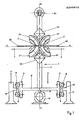
- FIG. 1 represents a frontal view of the device of the invention under working conditions i.e. during the jointing phase.
- the said device is comprised substantially by a repeater 1, supported by a carriage that is mobile alternately, in the both senses, between the two supporting tables 3 and 4 which are coplanar and side-by-side to each other, and parallel to the line separating said tables i.e. perpendicular to the drawing plane.
- the carriage comprises a vertical slab 5, mounted on a double-T shaped horizontal beam 6. At least in correspondence of its two extremities, upon each wing 7, in an axially outer position with respect to the slab 5, said the beam is provided with a couple of wheels 8 and 9 presenting a central V-shaped breasthook.
- the wheels run along a guide 10, fixed to the base of the machine through suitable supports 11, which present their opposite ends tapered in a V-shape for permitting a kinematic coupling with the said couple of wheels.
- the movement of the carriage along the guides 10, is determined by a motor 12 that forces the rotation of an endless screw 13 upon which is coupled a bush 14, fixed in a solid way to the beam 6 by means of opportune fixing means, such as, for example, a flange 15.
- the vertical slab 5 supports a U-shaped frame 16, disposed horizontally in such a way as to present its lower arms 17 and its upper arms 18 disposed respectively below and above the supporting tables for the fabric lengths.
- a supporting element 19 At the ends of the lower arm 17, there is fixed a supporting element 19, a prism for convenience sake, which is connected to the said arm, in correspondence of one of the bases.
- the orientation of the prism is such, that its axis lies in a vertical plane m-m (FIG. 1), but inclined with respect to the horizontal lying plane h-h of the fabric length, and precisly, from top to bottom, proceeding from the end connected to the U-shaped arm to the opposite end.
- intersection of the vertical plane m-m with the horizontal lying plane h-h for the fabric lengths determines a fixed line, with respect to the apparatus of the invention, along which the translation of the carriage 5 takes place and the jointing of the two fabric lengths.
- this joining line the 'seam-line'.
- the prism presents two faces turned upward and two faces turned downwards, with all the faces being inclined downwards
- a frusto-conical roller (20, 21) On each face, of the two upper faces, there is mounted a frusto-conical roller (20, 21) with its axis perpendicular to said face, disposed with the vertex of the conical surface that lies on the axis of the roller on the side opposite, with respect to the face of the supporting prism.
- the lateral surfaces of the two adjacent rollers (20, 21) are very close, or even meet in correspondence of the circumference with a greater diameter.
- a T-shaped flange 170 made fast with said end, with the T-base lying on the meridian plane m-m and the wings 171 lying in a horizontal plane, on opposite sides of said meridian plane.
- the above-said flange does not protrude vertically from the horizontal plane h-h, defined by the surface of the supporting tables 3 and 4, but it is preferably tangent to said plane.
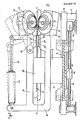
- the upper arm 18 of the U-shape is shorter than the corresponding lower arm; to its extremity there is hinge-connected the end of a small square 22 rotating around a horizontal axis, perpendicular to the above-said arm.
- the other extremity of the said small square is hinge-connected to the rod 23 of a cylinder 24 that, in its turn, is hinge-connected to the U- shaped frame opposite the extremity of the relative arms.
- a second supporting element opportunely a prism 25, substantially identical to that already described, provided with a similar couple of frusto-conical wheels (26, 27) symmetrically disposed with reference to the previous wheels, with respect to the horizontal plane.
- frusto-conical wheels 26, 27
- the only difference that has any importance with respect to the previously described complex consists in the orientation of the said prism that is now inclined from bottom to top.
- the blade 220 can conveniently be provided, on its flanks, with two horizontal wings 221, aligned with the surface of the rollers 26 and 27 that is turned towards the horizontal plane h-h, in such a way as to define along with the corresponding wings 171 an aperture that is substantially equal to the same thickness as the fabric to be jointed.
- the U-shaped arms delimit an opening having a width, in the direction parallel to the border of the supporting tables, of not lesser than the length of said border so much so that, when the jointing-group is found in correspondence of one extremity of the fabric length, the U-bend i.e. the connecting zone of the two arms, is outside the other extremity of the supporting table.
- any lengthier arms would involve constructive, static and .dinamic problems in consideration also, of the weight of the rolling-group borne at the extremities of the arms, with thus making it preferable to provide the piecing machine with two repeaters, to be disposed opposite each other and to be coaxially and reciprocally shiftable, in such a manner that each one of them provides with their reciprocal drawing apart movement, for effecting only a half-joint, from the centre line of the strip to one extremity.
- the length of the arms of the U-shaped frame can be reduced by about half with not only providing constructive advantages but, with also increasing the productive yield of the apparatus thanks to the speed with which these joints are executed and the idle strokes of the repeaters.
- the productivity of the said device is greater than that had with a similar device, having the same velocity, which nevertheless carries out the jointing by starting from one extremity of the fabric length till the opposite end. As a matter of fact, it must first wait for the correct positioning of the exiting-edge "U" of the strip before returning the repeater to its initial position, at the other end of the seam-line.
- the device has been described as having a lower, fixed group of rollers and an upper, mobile group of rollers, in the vertical plane.
- the mobility of at least one of these groups is essential for causing the device to function.
- the device can be realized either with the upper fixed group of rollers and the lower mobile group of rollers or else, with both the groups being of mobile rollers, in the vertical plane.
- FIG. 3 illustrates a variation in the execution for the device of the invention according to which the frame is now realized with a scissors type of device (160) wherein the two supporting arms of the groups of rollers form so to say the blades of the scissors.
- the two arms 161 and 162 are fixed to each other by a hinge 163 having a horizontal axis, with said axis lying on the horizontal plane h-h and with their movement relative to their opening and closing, being controlled by a cylinder- piston group 164 hinged to the extremities of the arms on the sides opposite the groups of rollers, with respect to the above-said hinge.
- FIG . 3 very schematically illustrates this version of the device of the invention since the groups ot rollers are identical to those described and moreover, after the explanations given its application to the device already described and illustrated in FIG. 2, is a very obvious matter for any technician of the field.
- the two "U-shaped" arms could be connected to each other through a vertical small plate 28 that would have the advantage of stiffening the device and render it more compact, and allow for eliminating the lateral connection between the two supporting arms, the reduction of their total length and above all, the lessening of the length of the cantilevered part with respect to the previously illustrated version.
- the solution illustrated attains another advantage, offered by the possibility of eliminating the above-said sensory devices, necessary for the correct positioning of the entering-edges of the fabric lengths that must be joined, and for the exiting of the tail-end of the strip.
- the said correct positioning can be obtained by simply sending against said abutting small plate 28 surface, from opposite sides, the two portions of fabric to be joined i.e. the new length that has arrived. and the tail-end of the strip under formation which, in said case, are found automatically aligned parallelly to each other and at a precise, pre-fixed distance apart.
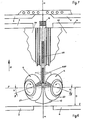
- FIGS. 4 and 5 illustrate respectively two diverse variations of realization of the couple of rollers 20, 21, in the rolling- group in a lower position to the table for supporting the lengths.
- the rollers 26, 27, that are mounted on the upper rolling-group will be quite identical to those of the lower group however, they have not been shown in the details of the figure solely for the purpose of allowing for a greater simplicity in the description and for facilitating the interpretation of the drawings.
- these rollers have a very complex structure that is, above all, originated by the coupling of the two frusto-conical bodies (210, 211) in correspondence of the greater bases.
- the roller (21) therefore presents a circumference (29), that has a maximum diameter, which divides into two facing portions the lateral surface of the roller.
- the axially exterior surface is a conical surface "a" with its vertex VI lying on the axis of the roller and with the flare angle equal to 90° or preferably, slightly over, that developes from said circumferential line with a maximum diameter.
- the working surface "a” is fixed to the lesser base "c" of the said frusto-conical body, through a second conical surface "b” having a flare angle that is substantially greater than 90° and hence, vertex Y2 lying on the axis of the roller, in an intermediate position between Vl and the lesser base of the roller.
- the axially interior surface of the roller is conical with the vertex V3 on the axis of the roller, disposed on the same side as the supporting prism.
- the flare angle of said surface will be about 90° in such a way as to realize a corner, also of about 90°, in correspondence of the circumference with a maximum diameter.
- said axially interior surface does not undergo any direct intervention and hence, the axially interior frusto-conical body can also be omitted.
- the rollers it is appropriate for the rollers to rotate synchronously to one another.
- the said axially interior surface, of the roller of the invention is provided with a plurality of teeth 30 disposed according to the generatrices of the said conical surface, which mesh with a corresponding toothed crown made on the adjacent roller.
- the Applicant has been able to verify that it is always appropriate, but at times even essential, for the front surface of said toothed crowns not to coincide with the working surface "a" of the roller.
- the working surface of the rollers partially penetrates into the fabric, especially when the generatrix of said surface, as already said, is not parallel, but rather incident on the surface of the said fabric length.
- the reciprocal coupling of the two toothed crowns can negatively influence the quality of the joint, since the relative teeth would sink too deeply into the surface of the fabric, with causing a part of the elastomeric material to be shifted from one side of the seam-line to the other i.e. of the meridian plane m-m, with accumulating said material in the junction zone.
- the front surface of the teeth must be made lower with respect to the surface "a”, enough for not permitting the tooth to sink into the elastomer material of the fabric and hence, with the consequent shifting of the material into the junction zone.
- the value given to said lowering of the teeth therefore depends mainly upon the type of fabric concerned in particular, upon the characteristics of the elastomeric material, as well as upon the pressure exercised on the fabric by the couples of opposed rollers disposed in the verticla plane.
- the Applicant has found it convenient to let there be, between the surface "a" of the roller and the front surface of the relative toothed crown, a step having a height comprised within the range of between 0,5 and 1 mm.
- the axially interior conical surface presents an undercut 31 (according to an appropriate variation of embodiment for said rollers shown in FIG. 5), having such a width as to allow for housing the toothed crown of the roller.
- the above-said roller can be conveniently realized, for example, by a substantially frusto-conical bush 32 presenting two conical surfaces (f, k) turned up on opposide sides with respect to the axis of the bush, and connected to one another along the circumference 290 having a maximum diameter, with each said surface having a flare angle equal to 90°, screwed down on a frusto-conical pivot 33 presenting, in an axially interior position, a conical toothing 34 whose maximum diameter 295 is less than the maximum diameter of the bush.
- the two rollers can be coupled to one another, with a reciprocal meshing of the two toothed crowns, and with obtaining the synchronism of the rotation movement and simultaneously, the reciprocal approaching to side-by-side of the two working surfaces "f" in correspondence of the corner which identifies the circumference 290 having a maximum diameter.
- the axial distance between the two facing surfaces "K" becomes independent from the dimensions of the toothed crown and can be reduced to null by bringing the two surfaces into reciprocal contact.
- rollers are mounted in pairs, upon the two supporting prisms as previously stated and as illustrated in the figures of the herewith attached drawing sheets.
- the angle w between the plane containing the axes of the two adjacent rollers and the plane v-v is the angle that directly influences the jointing operation.
- the value of said angle w determines the inclination of the generatrix "g" of the conical surface "a” that results as being tangent to the horizontal plane ( FIG . 6), with respect to the perpendicular direction of the seam-line.
- angle w depends mainly upon the type of fabric concerned and upon the pressure desired for the jointing. In any case, according to the invention, the value of w should not exceed 25° and, tor preference, it should be comprised between 5° and 15°.
- the jointing takes place when a new rubberized fabric length 36, arrives at the supporting table 3 for being jointed onto the tail-end 35 of the strip formed by the series of previously-joined lengths; said tail-end being disposed on the supporting table 4.
- the upper rolling-group (that was raised at the termination of the previous jointing operation) is, first and foremost, lowered, and taken (FIG. 2) trom the at- rest position (see broken-line) to the working position (see full-line), in such a way as to press the edges of the strip 35 and of the length 36, between the two pairs of opposed rollers, respectively 21-26 and 20-27 and precisely in correspondence of the upper portions "a" (see broken-line in FIG. 6) placed astride the generatrices "g".
- the carriage motor is actioned which, through the coupling of the lead-nut and endless-screw, drags the repeatere along the seam-line.
- each roller exercises a thrust with a horizonal component force, directed perpendicularly to the seam-line, on the corresponding fabric surface. Said thrust draws together the respective entering and exiting edges of the two lengths, with simultaneously pressing them one against the other, with thus obtaining the reciprocal welding due to the sticky effect of the raw elastomeric material.
- the jointing, between the two fabrics does not take place simultaneously along the entire extension of the edge but, in successive points and progressively from one end to the other of the pair of adjacent lengths.
- rollers cause the shifting of a narrow portion of fabric in each edge towards the seam-line, till placing the two portions in reciprocal contact and/or pressing, one against the other, the two fabric portions gripped between each pair of vertically opposed rollers.
- the reciprocal drawing together of the edges is diffused upstream of the joining point so that in the absence of a spacer-element for keeping the edges apart such as precisely said blade, the pairs of opposed rollers would grab hold of fabric portions, progressively predisposed even nearer to each other, so that these would results as being in reciprocal contact, even prior to the pressing action by the rollers has been initiated.
- the above-described blade assures a correct and constant distancing of the edges to be joined, along the entire development of the joint.
- the two repeaters with their relative rolling-groups, are entirely identical to each other, so much so that the previous description applies to both of them. They are mounted on their respective carriages, in a position with the rolling-groups facing, and they move along the same seam-line.
- the second repeater (not shown) will have its rolling-groups disposed at a certain distance from the above-said line 1-1. Moreover, it will present the upper rolling group as still raised with respect to the two lengths.
- the jointing operation commences at this point.
- the two repeaters move together in the same direction (indicated with the arrow M in FIG. 6), while the rolling-groups of the first repeater, carry out the jointing.
- the first repeater has reached the position shown in FIG. 6, after realizing a small joining tract D, the second repeater will already have surpassed, with its rolling-groups, the line 1 - 1 , so much so that these latter will be found in correspondence of a portion of already joined fabric.
- the upper rolling-group of the second repeater is lowered onto the fabric.
- the second repeater inverts the direction of movement and, after recrossing over the already welded tract D, it carries out the jointing of the two lengths, till the opposite extremity.
- the upper rolling-groups of the two repeaters After realizing the jointing of the lengths, along the entire length of the facing edges, the upper rolling-groups of the two repeaters, through the actioning, in the inverted sense, by the controlling device (of cylinder 24 in the illustrated example) are raised from the fabric, whilst an opportune strip winding device (not shown) recuperates the strip portion corresponding to the length of the just-joined length, till bringing the exiting-edge U of the above-said length in correspondence of the seam-line, for being welded to the new length arriving on table 3. Simultaneous to the movement of the strip, or when the latter has stopped moving, in accordance with the diverse versions of the above-described device, the two repeaters are taken to the centre of the supporting plane, ready for effecting the new joint.
- the pairs of opposed rollers, of the rolling-group grasp the edge to be joined, on both sides of the surface, and press it directly against the edge opposite, with a pre-determined and constant force, without giving rise to any accumulation, or thinning out, of the reinforcing cords in the junction zone and without effecting any shifting of the elastomeric material.
- the strip realized in this way, has proved to possess high qualitative characteristics both, as far as regards the jointing which has shown to be extremely reliable, as well as with regard to the uniformity in distribution of the eventual reinforcing cords. So much so that the junction zone does not results as being distinguishable any longer in the finished product and not even when examined under X-Ray.
- the apparatus results as being relatively simple, but with nevertheless, a precise structure that is easy to control, and reliable as far as concerns its functioning, with also having a high productive yield, during exercise.
Landscapes
- Engineering & Computer Science (AREA)
- Mechanical Engineering (AREA)
- Textile Engineering (AREA)
- Physics & Mathematics (AREA)
- Fluid Mechanics (AREA)
- Tyre Moulding (AREA)
- Lining Or Joining Of Plastics Or The Like (AREA)
- Treatment Of Fiber Materials (AREA)
- Replacement Of Web Rolls (AREA)
Applications Claiming Priority (2)
| Application Number | Priority Date | Filing Date | Title |
|---|---|---|---|
| IT2068486 | 1986-06-05 | ||
| IT2068486A IT1190035B (it) | 1986-06-05 | 1986-06-05 | Metodo e apparecchiatura per la giunzione testa a testa di spezzoni di tessuto gommato |
Publications (2)
| Publication Number | Publication Date |
|---|---|
| EP0248412A2 true EP0248412A2 (de) | 1987-12-09 |
| EP0248412A3 EP0248412A3 (de) | 1990-01-17 |
Family
ID=11170538
Family Applications (1)
| Application Number | Title | Priority Date | Filing Date |
|---|---|---|---|
| EP19870108015 Withdrawn EP0248412A3 (de) | 1986-06-05 | 1987-06-03 | Verfahren und Vorrichtung zum Stossverbinden von mit Gummi beschichteten Textilbändern |
Country Status (5)
| Country | Link |
|---|---|
| US (1) | US4867823A (de) |
| EP (1) | EP0248412A3 (de) |
| JP (1) | JPS6322455A (de) |
| BR (1) | BR8703387A (de) |
| IT (1) | IT1190035B (de) |
Cited By (3)
| Publication number | Priority date | Publication date | Assignee | Title |
|---|---|---|---|---|
| NL8900031A (nl) * | 1988-01-07 | 1989-08-01 | Mitsubishi Heavy Ind Ltd | Verbindingsinrichting voor met koord versterkte bandvormige materialen. |
| ES2070703A2 (es) * | 1992-01-06 | 1995-06-01 | Goodyear Tire & Rubber | Aparato para empalmar a tope material en capas. |
| GB2318082A (en) * | 1996-10-08 | 1998-04-15 | Sumitomo Rubber Ind | Method and apparatus for joining rubbery fabric |
Families Citing this family (15)
| Publication number | Priority date | Publication date | Assignee | Title |
|---|---|---|---|---|
| IT1241254B (it) * | 1990-06-08 | 1993-12-29 | Firestone International Developments.P.A. | Dispositivo per la giunzione di materiale autoadesivo in foglio di gomma crusa |
| US6375770B1 (en) | 1990-07-24 | 2002-04-23 | O'neill, Inc. | Apparatus and method for forming an adhesively bonded seam between resiliently compressible fabric sheets |
| CA2087834C (en) * | 1990-07-24 | 2003-01-28 | Mark J. Meltzer | Apparatus and method for forming an adhesively bonded seam between resiliently compressible fabric sheets |
| DE4430453C2 (de) * | 1994-08-27 | 1996-08-14 | Fischer Maschf Karl E | Spleißmaschine |
| US6533891B1 (en) | 1999-02-03 | 2003-03-18 | The Goodyear Tire & Rubber Company | Butt splicing of elastomeric sheets |
| DE10156472A1 (de) * | 2001-11-16 | 2003-06-05 | Continental Ag | Stumpfes Spleissen von gummierten Bandabschnitten |
| US7073552B2 (en) * | 2002-12-20 | 2006-07-11 | The Goodyear Tire & Rubber Company | Tire preparation ply manufacturing apparatus and method |
| JP4668564B2 (ja) * | 2004-08-05 | 2011-04-13 | 株式会社ブリヂストン | 接合装置及び接合方法 |
| JP5221412B2 (ja) * | 2009-02-23 | 2013-06-26 | 三菱重工マシナリーテクノロジー株式会社 | カーカスプライの接合装置 |
| DE102010005758B3 (de) * | 2010-01-25 | 2011-06-16 | Thyssenkrupp Lasertechnik Gmbh | Vorrichtung und Verfahren zum Führen von miteinander entlang ihrer Längskanten zu fügender Bänder |
| CN103429418B (zh) * | 2011-03-15 | 2016-04-06 | 株式会社普利司通 | 用于片状构件的自动拉链装置和用于制造片状产品的方法 |
| FR2975039B1 (fr) | 2011-05-10 | 2017-02-10 | Soc De Tech Michelin | Procede de realisation d'une nappe carcasse de pneumatique |
| JP5576992B2 (ja) * | 2011-11-08 | 2014-08-20 | 株式会社ブリヂストン | シート状部材のバットジョイント装置及び、それの使用方法 |
| WO2021034438A1 (en) * | 2019-08-21 | 2021-02-25 | Bridgestone Americas Tire Operations, Llc | Apparatus and method for automatic tire ply stitching |
| WO2021034437A1 (en) | 2019-08-21 | 2021-02-25 | Bridgestone Americas Tire Operations, Llc | Apparatus and method for automatic tire ply stitching |
Family Cites Families (9)
| Publication number | Priority date | Publication date | Assignee | Title |
|---|---|---|---|---|
| US2088889A (en) * | 1934-05-04 | 1937-08-03 | Us Rubber Co | Stitching device for tire building machines |
| US2702070A (en) * | 1951-10-16 | 1955-02-15 | Goodrich Co B F | Apparatus for splicing adhesive material |
| CH566858A5 (de) * | 1973-02-02 | 1975-09-30 | Dynamit Nobel Ag | |
| US3909341A (en) * | 1973-12-12 | 1975-09-30 | Owens Corning Fiberglass Corp | Splicing tool |
| US4057455A (en) * | 1975-03-11 | 1977-11-08 | Cooper Tire And Rubber Company | Tire stitching apparatus |
| FR2446170A1 (fr) * | 1979-01-10 | 1980-08-08 | Zelant Gazuit | Machine permettant de joindre bord a bord des plis en caoutchouc non vulcanise |
| US4231836A (en) * | 1979-02-02 | 1980-11-04 | Gislaved Ab | System for automatic joining and rolling up of cord strips |
| IT8167978A0 (it) * | 1981-07-15 | 1981-07-15 | Firestone Int Dev Spa | Dispositivo di giunzione per tele di pneumatici |
| IT1158835B (it) * | 1983-03-21 | 1987-02-25 | Firestone Int Dev Spa | Attrezzo motorizzato per la giunzione di tele autoadesive di gomme cruda |
-
1986
- 1986-06-05 IT IT2068486A patent/IT1190035B/it active
-
1987
- 1987-06-03 EP EP19870108015 patent/EP0248412A3/de not_active Withdrawn
- 1987-06-04 US US07/058,231 patent/US4867823A/en not_active Expired - Fee Related
- 1987-06-05 JP JP62141308A patent/JPS6322455A/ja active Pending
- 1987-06-05 BR BR8703387A patent/BR8703387A/pt unknown
Cited By (4)
| Publication number | Priority date | Publication date | Assignee | Title |
|---|---|---|---|---|
| NL8900031A (nl) * | 1988-01-07 | 1989-08-01 | Mitsubishi Heavy Ind Ltd | Verbindingsinrichting voor met koord versterkte bandvormige materialen. |
| US4954205A (en) * | 1988-01-07 | 1990-09-04 | Mitsubishi Jukogyo Kabushiki Kaisha | Joining device for cord-reinforced belt-shaped materials |
| ES2070703A2 (es) * | 1992-01-06 | 1995-06-01 | Goodyear Tire & Rubber | Aparato para empalmar a tope material en capas. |
| GB2318082A (en) * | 1996-10-08 | 1998-04-15 | Sumitomo Rubber Ind | Method and apparatus for joining rubbery fabric |
Also Published As
| Publication number | Publication date |
|---|---|
| JPS6322455A (ja) | 1988-01-29 |
| US4867823A (en) | 1989-09-19 |
| IT8620684A1 (it) | 1987-12-05 |
| IT8620684A0 (it) | 1986-06-05 |
| BR8703387A (pt) | 1988-03-22 |
| IT1190035B (it) | 1988-02-10 |
| EP0248412A3 (de) | 1990-01-17 |
Similar Documents
| Publication | Publication Date | Title |
|---|---|---|
| EP0248412A2 (de) | Verfahren und Vorrichtung zum Stossverbinden von mit Gummi beschichteten Textilbändern | |
| EP0310417B1 (de) | Verfahren und Vorrichtung zum Aufbringen eines Wulstfüllers auf einen Wulstkernring | |
| US5120297A (en) | Machine for creasing and cutting endless webs of cardboard and the like | |
| US4614512A (en) | Sheet folding machine | |
| EP0061631B1 (de) | Vorrichtung zum Stapeln von blattartigen Gegenständen | |
| JP2898086B2 (ja) | 連続的に搬送される重なり合った物品の流れを分割する装置 | |
| EP0457304A1 (de) | Beutelherstellungsapparat | |
| US5001954A (en) | Sealing system for a cutting table having vacuum clamping | |
| NL8101021A (nl) | Werkwijze en inrichting voor het vervaardigen van een verbinding van vezelverbanden. | |
| US5086636A (en) | Stretch-forming machine | |
| DE3817993C2 (de) | Einschlagvorrichtung für eine Maschine zum Herstellen von Bucheinbanddecken | |
| HUT63738A (en) | Method and apparatus for forming pretzels from paste fibres made in advance | |
| WO1981003504A1 (en) | Sheet production system with hem expander | |
| GB2135238A (en) | Producing tubes for packaging | |
| EP1621321B2 (de) | Maschine zur formung von schlauchförmigen längen aus verpackungsfolie | |
| ITBO930257A1 (it) | Dispositivo per la giunzione automatica di nastri di ridotte dimensioni trasversali. | |
| US2641167A (en) | Bag bottom forming device | |
| CA1143268A (en) | Forming means | |
| ITVR980067A1 (it) | Procedimento per la suddivisione di un nastro o filone di prodotto gommoso in singole porzioni e dispositivo per la messa in opera di tale procedimento. | |
| DE848235C (de) | Verfahren und Geraet zum Schneiden eines fortlaufenden Glasbandes in gleich grosse Glastafelstuecke | |
| JP2000026020A (ja) | シ―トの送り手段と、シ―トを送る方法 | |
| US2911932A (en) | Tube making machine | |
| EP0294450A1 (de) | Verbesserung bei der behandlung weicher gewebe. | |
| SU441751A1 (ru) | Установка дл соединени в фальц боковин с обечайкой изделий -образной формы | |
| CN112499105A (zh) | 一种纤维砂浆制备用加工系统 |
Legal Events
| Date | Code | Title | Description |
|---|---|---|---|
| PUAI | Public reference made under article 153(3) epc to a published international application that has entered the european phase |
Free format text: ORIGINAL CODE: 0009012 |
|
| AK | Designated contracting states |
Kind code of ref document: A2 Designated state(s): DE ES FR GB GR LU |
|
| PUAL | Search report despatched |
Free format text: ORIGINAL CODE: 0009013 |
|
| AK | Designated contracting states |
Kind code of ref document: A3 Designated state(s): DE ES FR GB GR LU |
|
| STAA | Information on the status of an ep patent application or granted ep patent |
Free format text: STATUS: THE APPLICATION IS DEEMED TO BE WITHDRAWN |
|
| 18D | Application deemed to be withdrawn |
Effective date: 19900718 |
|
| RIN1 | Information on inventor provided before grant (corrected) |
Inventor name: PIZZORNO, AUGUSTO |