EP0248218A2 - Method for determining the bubble point or the largest pore of membranes or filter materials - Google Patents
Method for determining the bubble point or the largest pore of membranes or filter materials Download PDFInfo
- Publication number
- EP0248218A2 EP0248218A2 EP87106444A EP87106444A EP0248218A2 EP 0248218 A2 EP0248218 A2 EP 0248218A2 EP 87106444 A EP87106444 A EP 87106444A EP 87106444 A EP87106444 A EP 87106444A EP 0248218 A2 EP0248218 A2 EP 0248218A2
- Authority
- EP
- European Patent Office
- Prior art keywords
- pressure
- space
- gas
- membrane
- liquid
- Prior art date
- Legal status (The legal status is an assumption and is not a legal conclusion. Google has not performed a legal analysis and makes no representation as to the accuracy of the status listed.)
- Granted
Links
Images
Classifications
-
- B—PERFORMING OPERATIONS; TRANSPORTING
- B01—PHYSICAL OR CHEMICAL PROCESSES OR APPARATUS IN GENERAL
- B01D—SEPARATION
- B01D65/00—Accessories or auxiliary operations, in general, for separation processes or apparatus using semi-permeable membranes
- B01D65/10—Testing of membranes or membrane apparatus; Detecting or repairing leaks
- B01D65/102—Detection of leaks in membranes
-
- G—PHYSICS
- G01—MEASURING; TESTING
- G01N—INVESTIGATING OR ANALYSING MATERIALS BY DETERMINING THEIR CHEMICAL OR PHYSICAL PROPERTIES
- G01N15/00—Investigating characteristics of particles; Investigating permeability, pore-volume or surface-area of porous materials
- G01N15/08—Investigating permeability, pore-volume, or surface area of porous materials
- G01N15/088—Investigating volume, surface area, size or distribution of pores; Porosimetry
-
- G—PHYSICS
- G01—MEASURING; TESTING
- G01N—INVESTIGATING OR ANALYSING MATERIALS BY DETERMINING THEIR CHEMICAL OR PHYSICAL PROPERTIES
- G01N15/00—Investigating characteristics of particles; Investigating permeability, pore-volume or surface-area of porous materials
- G01N15/08—Investigating permeability, pore-volume, or surface area of porous materials
- G01N15/082—Investigating permeability by forcing a fluid through a sample
- G01N15/0826—Investigating permeability by forcing a fluid through a sample and measuring fluid flow rate, i.e. permeation rate or pressure change
-
- G—PHYSICS
- G01—MEASURING; TESTING
- G01N—INVESTIGATING OR ANALYSING MATERIALS BY DETERMINING THEIR CHEMICAL OR PHYSICAL PROPERTIES
- G01N15/00—Investigating characteristics of particles; Investigating permeability, pore-volume or surface-area of porous materials
- G01N15/08—Investigating permeability, pore-volume, or surface area of porous materials
- G01N2015/084—Testing filters
Definitions
- the present invention relates to a method for determining the blowing point or the largest pore of membranes or filter materials, which are arranged in a container and divide this container into a first and second space, in which the first space with gas, the second space and the pores of the membrane or the filter material are filled with a liquid wetting the membrane or the filter material, then the pressure in the first space, the gas space, is increased over time from the normal pressure until at least the pressure in the gas space is determined, in which the gas displaces the liquid from the largest pore of the membrane or the filter material, and by means of which the blowing point is determined on the basis of the prevailing gas space pressure, or by means of which the cross-sectional dimension of the large pore can be calculated.
- the pressure in the gas space at which the gas displaces the liquid from the largest pore of the membrane or the filter material is determined in the known method by measuring the differential pressure between the liquid space and the environment, the change in time of this differential pressure as a measure of the flow rate of the Gas is used through the pores. In the case of larger pores, the flow rate can also be measured directly (ASTM F 3l6-7O) or the rise of bubbles can be observed visually (ASTM I28-6l).
- a method is also to be made available with which the blowing point and the largest pore diameter can be determined for entire modules, even for membranes or filter materials that are already built into their housing.
- This object is achieved in the method mentioned at the outset in that the sound intensity in the liquid space is determined and the gas space pressure is determined during the temporal increase in the gas space pressure, at which an abrupt increase in the sound intensity can be determined.
- the microphone should not be arranged in an area in which such gas bubbles can rise.
- the measuring vessel is expediently shielded against external interference (impact sound, conversations, etc.).
- the external interference can also be effectively reduced by measuring the sound intensity in the ultrasonic range, ie at frequencies above 20 kHz. Sound-absorbing insulation around the measuring vessel is recommended.
- the measuring vessel should consist of a material in which the losses resulting from the sound reflection on the vessel wall can be kept particularly small. Glass or metal has proven to be the best material for the measuring vessel.
- the distance between opposite walls should be at least 10 cm. - It must be ensured that the membranes or filter materials are well wetted. In the case of large membrane or filter material surfaces, it has proven to be an advantage if these are first evacuated and then slowly flooded. Here, the pores are emptied by applying a negative pressure before the pores are filled with the wetting liquid. If the membranes or filter materials are poorly wetted, air pockets can occur. This triggers a relatively high background level when the method according to the invention is carried out.
- the method according to the invention can be carried out by immersing the membrane in the housing in a liquid, for example water, the microphone now being arranged in this liquid. This arrangement can always be selected if the sound or ultrasound can penetrate the housing wall. In this way, an effective and simple production control for mass transfer modules or of membranes already embedded in the housing is possible. It has been determined that Pores can be measured by the method according to the invention, the area of which is 100 times larger than the area of the samples, which can be measured with the required accuracy using the method described in DE-GM 82 122 O94.
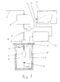
- FIG. 1 An arrangement for carrying out the method according to the invention is shown schematically in FIG.
- space 5 and the inner cavity of the hollow fiber membrane form the gas space, which is connected via line 3 to a pressure control 2, which controls the gas supplied via line l, for example nitrogen, with the desired pressure, which is increased over time.
- a line pressure meter 4 is coupled to line 3, the output signals of which are transmitted via line 13 to a Yt recorder which records the pressure signal over time.
- the sample 6 is immersed in liquid 7, which is filled into a vessel.
- the vessel is encased with sound insulation 10.
- the vessel is closed at the top with a sound insulation 11 as a lid.
- a microphone for example a waterproof piezoelectric quartz sensor, is arranged beneath the sample 6, the signals of which are fed via the line 9 to a computing unit 12.
- the signals coming from the microphone 8 are filtered with regard to the frequency (for example to utilize the amplification resulting from the natural frequency of the microphone used), electrically amplified and rectified.
- the filtering is also necessary to suppress noise from possible turbulence in the measuring liquid.
- the amplified and filtered signals are also fed via a line l4 to the Y-t recorder l5, which also records the signal of the sound intensity over time in parallel with the pressure signal.
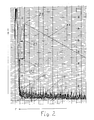
- Figure 2 shows what such a diagram can look like.
- the method according to the invention is particularly economical if membrane or filter areas of more than 0.1 m2 are to be tested.
- the blowing point and the largest pore diameter can be easily determined.
- ⁇ B is a constant that is mainly inherent in the wetting liquid.
- the values for ⁇ B are, for example, at 25 ° C for isopropanol O, 6ll ⁇ m ⁇ bar and for H2O 2.O7 ⁇ m ⁇ bar.
Landscapes
- Chemical & Material Sciences (AREA)
- General Health & Medical Sciences (AREA)
- Pathology (AREA)
- Physics & Mathematics (AREA)
- Health & Medical Sciences (AREA)
- Life Sciences & Earth Sciences (AREA)
- Analytical Chemistry (AREA)
- Dispersion Chemistry (AREA)
- General Physics & Mathematics (AREA)
- Biochemistry (AREA)
- Immunology (AREA)
- Chemical Kinetics & Catalysis (AREA)
- Separation Using Semi-Permeable Membranes (AREA)
- Investigating Or Analyzing Materials By The Use Of Ultrasonic Waves (AREA)
- Sampling And Sample Adjustment (AREA)
- Filtering Materials (AREA)
Abstract
Bei der Bestimmung des Blaspunktes bzw. der größten Pore einer Membran bzw. eines Filterwerkstoffes wird die Membran bzw. der Filterwerkstoff in einem Behälter angeordnet, wobei die Membran bzw. der Filterwerkstoff diesen Behälter in zwei Räume teilt. Danach wird der erste Raum mit Gas, und der zweite Raum und die Poren der Membran (des Filterwerkstoffs) mit einer benetzenden Flüssigkeit gefüllt. Nun wird der Druck im Gasraum zumindest solange erhöht, bis das Gas die Flüssigkeit aus der größten Pore verdrängt. Durch den hierbei herrschenden Gasraumdruck ist der Blaspunkt festgelegt, bzw. kann die Querschnittsdimension der größten Pore berechnet werden. Erfindungsgemäß wird vorgeschlagen, daß der zum Blaspunkt gehörige Gasraumdruck durch Messung der Schallintensität im Flüssigkeitsraum dann bestimmt ist, wenn eine sprunghafte Erhöhung der Schallintensität eintritt. Die Messung der Schallintensität wird bevorzugt im Ultraschallbereich durchgeführt. When determining the blowing point or the largest pore of a membrane or a filter material, the membrane or the filter material is arranged in a container, the membrane or the filter material dividing this container into two spaces. The first chamber is then filled with gas, and the second chamber and the pores of the membrane (of the filter material) with a wetting liquid. Now the pressure in the gas space is increased at least until the gas displaces the liquid from the largest pore. The blowing point is determined by the prevailing gas space pressure, or the cross-sectional dimension of the largest pore can be calculated. According to the invention, it is proposed that the gas space pressure belonging to the blowing point be determined by measuring the sound intensity in the liquid space when there is a sudden increase in the sound intensity. The measurement of the sound intensity is preferably carried out in the ultrasound range.
Description
Gegenstand der vorliegenden Erfindung ist ein Verfahren zur Bestimmung des Blaspunktes bzw. der größten Pore von Membranen oder Filterwerkstoffen, welche in einem Behälter angeordnet sind und diesen Behälter in einen ersten und zweiten Raum unterteilen, bei dem der erste Raum mit Gas, der zweite Raum und die Poren der Membran bzw. des Filterwerkstoffes mit einer die Membran bzw. den Filterwerkstoff benetzenden Flüssigkeit gefüllt werden, anschließend der Druck im ersten Raum, dem Gasraum, vom Normaldruck ausgehend solange über die Zeit erhöht wird, bis mindestens der Druck im Gasraum festgestellt wird, bei welchem das Gas die Flüssigkeit aus der größten Pore der Membran bzw. des Filterwerkstoffes verdrängt, und durch welchen aufgrund des dabei herrschenden Gasraumdruckes der Blaspunkt festgelegt ist, bzw. durch welchen die Querschnittsdimension der größen Pore berechnet werden kann.The present invention relates to a method for determining the blowing point or the largest pore of membranes or filter materials, which are arranged in a container and divide this container into a first and second space, in which the first space with gas, the second space and the pores of the membrane or the filter material are filled with a liquid wetting the membrane or the filter material, then the pressure in the first space, the gas space, is increased over time from the normal pressure until at least the pressure in the gas space is determined, in which the gas displaces the liquid from the largest pore of the membrane or the filter material, and by means of which the blowing point is determined on the basis of the prevailing gas space pressure, or by means of which the cross-sectional dimension of the large pore can be calculated.
Derartige Verfahren sind beispielsweise aus dem DE-GM 82 l2 O94 bekannt. Der Druck im Gasraum, bei dem das Gas die Flüssigkeit aus der größten Pore der Membran bzw. des Filterwerkstoffes verdrängt, wird bei dem bekannten Verfahren durch Messung des Differenzdruckes zwischen Flüssigkeitsraum und Umgebung bestimmt, wobei die zeitliche Änderung dieses Differenzdruckes als Maß für die Durchflußmenge des Gases durch die Poren benutzt wird. Bei größeren Poren kann auch die Durchflußmenge direkt gemessen werden (ASTM F 3l6-7O), bzw. visuell das Aufsteigen von Blasen beobachtet werden (ASTM l28-6l).Such methods are known for example from DE-GM 82 122 O94. The pressure in the gas space at which the gas displaces the liquid from the largest pore of the membrane or the filter material is determined in the known method by measuring the differential pressure between the liquid space and the environment, the change in time of this differential pressure as a measure of the flow rate of the Gas is used through the pores. In the case of larger pores, the flow rate can also be measured directly (ASTM F 3l6-7O) or the rise of bubbles can be observed visually (ASTM I28-6l).
Bei den o.g. bekannten Verfahren ist jedoch, wie in der DE-PS 33 O6 647 erläutert, beobachtet worden, daß bei Größerwerden der zu prüfenden Membranfläche und der in dieser Membran vorliegenden Porendurchmesser schon vor Erreichen des durch den Blaspunkt definierten Druckes eine bestimmte Gasdurchflußmenge festgestellt werden kann, so daß das Meßergebnis hinsichtlich des Blaspunktes und der größten Pore verfälscht ist. Diese Durchflußmenge kann beispielsweise von einem Diffusionsfluß herrühren, welcher ursächlich mit der dem Partialdruck proportionalen Löslichkeit von Gasen in Flüssigkeiten und dem daraus folgenden Konzentrationsgradienten der Gasmoleküle in den Poren der Membran zusammenhängt. Nach dem in der DE-PS 33 O6 647 beschriebenen Verfahren wird diese unerwünschte Erscheinung zwar verhindert, doch ist die Anwendung des dort beschriebenen Verfahrens sehr zeitaufwendig, so daß es nur unter großem Personalaufwand möglich ist, die für eine Produktionskontrolle erforderliche Anzahl von Membranen oder von Membranmodulen einer Überprüfung zu unterziehen.In the above-mentioned known methods, however, it has been observed, as explained in DE-PS 33 O6 647, that when the membrane area to be tested and the pore diameter present in this membrane become larger, a certain gas flow rate is determined even before the pressure defined by the blowing point is reached can, so that the measurement result regarding the blowing point and the largest pore is falsified. This flow rate can result, for example, from a diffusion flow, which is causally related to the solubility of gases in liquids proportional to the partial pressure and the consequent concentration gradient of the gas molecules in the pores of the membrane. According to that in DE-PS 33 O6 647 The described process prevents this undesirable phenomenon, but the use of the process described there is very time-consuming, so that it is only possible with a large amount of personnel to check the number of membranes or membrane modules required for production control.
Aufgabe der vorliegenden Erfindung ist es nun, ein besonders einfaches, aber sicheres Verfahren der eingangs genannten Art zur Verfügung zu stellen, mit welchem unabhängig von der zu prüfenden Membranfläche bzw. Filterwerkstoff-Fläche und unabhängig von der Porengröße stets ausreichend genaue Werte des Blaspunktes und des größten Porendurchmessers ermittelt werden können. Speziell soll auch ein Verfahren zur Verfügung gestellt werden, mit welchem bei ganzen Modulen, ja sogar bei Membranen oder Filterwerkstoffen, die bereits in ihr Gehäuse eingebaut sind, Blaspunkt und größter Porendurchmesser bestimmt werden können.It is an object of the present invention to provide a particularly simple but reliable method of the type mentioned at the outset, with which independently of the membrane surface or filter material surface to be tested and regardless of the pore size, values of the blowing point and of which are always sufficiently precise largest pore diameter can be determined. In particular, a method is also to be made available with which the blowing point and the largest pore diameter can be determined for entire modules, even for membranes or filter materials that are already built into their housing.
Diese Aufgabe wird bei dem eingangs genannten Verfahren dadurch gelöst, daß während der zeitlichen Erhöung des Gasraumdruckes die Schallintensität im Flüssigkeitsraum bestimmt und der Gasraumdruck bestimmt wird, bei dem eine sprunghafte Erhöhung der Schallintensität feststellbar ist.This object is achieved in the method mentioned at the outset in that the sound intensity in the liquid space is determined and the gas space pressure is determined during the temporal increase in the gas space pressure, at which an abrupt increase in the sound intensity can be determined.
In der Regel wird hierzu ein Diagramm erstellt, in welchem die Schallintensität über dem hierzu gemessenen Gasraumdruck dargestellt wird. Hierbei stellt man fest, daß zunächst bei niedrigen Gasraumdrücken die Schallintensität (Geräuschpegel) gleichmäßig groß ist. Es ist nun festgestellt worden, daß bei Erreichen des zum Blaspunkt gehörenden Druckes die Schallintensität sprunghaft ansteigt.As a rule, a diagram is created for this purpose, in which the sound intensity is shown over the gas space pressure measured for this purpose. Here it is found that initially the sound intensity (noise level) is uniformly high at low gas space pressures. It has now been found that the sound intensity increases suddenly when the pressure belonging to the blowing point is reached.
Dieser sprunghafte Anstieg kann je nach Porenverteilung stetig oder unstetig erfolgen. Erfindungsgemäß ist festgestellt worden, daß der zum Blaspunkt gehörige Gasraumdruck immer dann erreicht ist, wenn die sprunghafte Erhöhung der Schallintensität auftritt.Depending on the pore distribution, this sudden increase can take place continuously or discontinuously. According to the invention it has been found that the gas space pressure associated with the blowing point is always reached when the sudden increase in sound intensity occurs.
Werden die Membranen oder Filterwerkstoffe in eine Prüfvorrichtung untersucht, wie sie beispielsweise in dem DE-GM 82 l2 O94 beschrieben ist, wird anstelle der dort beschriebenen Differenzdruckmessung nunmehr im Flüssigkeitsraum ein in der Regel wasserdichtes Mikrofon eingebaut, dessen Signale entsprechend verstärkt und gefiltert werden, bevor diese aufgezeichnet werden.If the membranes or filter materials are examined in a test device, as described, for example, in DE-GM 82 122 O94, instead of the differential pressure measurement described there, a generally waterproof microphone is now installed in the liquid space, the signals of which are appropriately amplified and filtered before these are recorded.
Bei der Durchführung des erfindungsgemäßen Verfahrens, welches sehr einfach uns schnell durchführbar ist, sollten allerdings folgende Punkte Beachtung finden:
- Da bei der Durchführung der Blaspunktmessung allgemein sich infolge des in jeder Flüssigkeit enthaltenen Gases Gasblasen bilden können, soll das Mikrofon nicht in einem Bereich angeordnet werden, in welchem solche Gasblasen aufsteigen können.
- Das Meßgefäß wird zweckmäßigerweise gegen äußere Störeinflüsse (Trittschall, Gespräche u.s.w.) abgeschirmt. Die äußeren Störeinflüsse können wirksam auch dadurch verringert werden, daß die Messung der Schallintensität im Ultraschallbereich, d.h. bei Frequenzen oberhalb von 2O kHz, durchgeführt wird. Eine schallabsorbierende Isolierung um das Meßgefäß ist zu empfehlen.
- Das Meßgefäß soll aus einem Material bestehen, bei welchem die bei der Schallreflexion an der Gefäßwand entstehenden Verluste besonders klein gehalten werden können. Als Material für das Meßgefäß hat sich Glas oder Metall bestens bewährt.
- Um den geringfügigen Einfluß der Meßgefäßwand weiter zu reduzieren, sollte der Abstand gegenüberliegender Wände mindestens lO cm betragen.
- Es ist dafür Sorge zu tragen, daß die Membranen bzw. Filterwerkstoffe gut benetzt sind. Bei großen Membran- bzw. Filterwerkstoff-Flächen hat es sich als Vorteil herausgestellt, wenn diese zunächst evakuiert und dann langsam beflutet werden. Hierbei werden vor der Befüllung der Poren mit der benetzenden Flüssigkeit die Poren durch Anlegen eines Unterdruckes entleert. Werden die Membranen bzw. Filterwerkstoffe schlecht benetzt, können Lufteinschlüsse auftreten. Hierdurch wird bei Durchführung des erfindungsgemäßen Verfahrens ein relativ hoher Untergrundpegel ausgelöst.When carrying out the method according to the invention, which is very easy for us to carry out quickly, the following points should be considered:
Since gas bubbles can generally form when the blow point measurement is carried out as a result of the gas contained in each liquid, the microphone should not be arranged in an area in which such gas bubbles can rise.
- The measuring vessel is expediently shielded against external interference (impact sound, conversations, etc.). The external interference can also be effectively reduced by measuring the sound intensity in the ultrasonic range, ie at frequencies above 20 kHz. Sound-absorbing insulation around the measuring vessel is recommended.
- The measuring vessel should consist of a material in which the losses resulting from the sound reflection on the vessel wall can be kept particularly small. Glass or metal has proven to be the best material for the measuring vessel.
- To further reduce the slight influence of the measuring vessel wall, the distance between opposite walls should be at least 10 cm.
- It must be ensured that the membranes or filter materials are well wetted. In the case of large membrane or filter material surfaces, it has proven to be an advantage if these are first evacuated and then slowly flooded. Here, the pores are emptied by applying a negative pressure before the pores are filled with the wetting liquid. If the membranes or filter materials are poorly wetted, air pockets can occur. This triggers a relatively high background level when the method according to the invention is carried out.
Werden Membranen oder Filterwerkstoffe getestet, die bereits in ein festes Gehäuse eingebettet sind, kann das erfindungsgemäße Verfahren dadurch durchgeführt werden, daß die Membran im Gehäuse in eine Flüssigkeit, beispielsweise Wasser, eingetaucht wird, wobei das Mikrofon nunmehr in dieser Flüssigkeit angeordnet wird. Diese Anordnung kann immer dann gewählt werden, wenn der Schall bzw. Ultraschall die Gehäusewand durchdringen kann. Auf diese Weise ist eine wirksame und einfache Produktionskontrolle für Stoffaustauschermodule bzw. von bereits im Gehäuse eingebetteten Membranen möglich. Es ist ermittelt worden, daß Poren nach dem erfindungsgemäßen Verfahren gemessen werden können, deren Fläche lOOO mal größer ist als die Fläche der Proben, welche nach der im DE-GM 82 l2 O94 beschriebenen Methode mit der erforderlichen Genauigkeit gemessen werden können.If membranes or filter materials that are already embedded in a solid housing are tested, the method according to the invention can be carried out by immersing the membrane in the housing in a liquid, for example water, the microphone now being arranged in this liquid. This arrangement can always be selected if the sound or ultrasound can penetrate the housing wall. In this way, an effective and simple production control for mass transfer modules or of membranes already embedded in the housing is possible. It has been determined that Pores can be measured by the method according to the invention, the area of which is 100 times larger than the area of the samples, which can be measured with the required accuracy using the method described in DE-GM 82 122 O94.
Die Erfindung wird anhand der nachfolgenden Figuren näher erläutert.The invention is explained in more detail with reference to the following figures.
Es zeigen:
- Figur l schematisch eine Anordnung zur Durchführung des erfindungsgemäßen Verfahrens,
Figur 2 ein bei Durchführung des erfindungsgemäßen Verfahrens erstelltes Diagramm.
- FIG. 1 schematically shows an arrangement for carrying out the method according to the invention,
- Figure 2 is a diagram created when performing the inventive method.
In Figur l ist schematisch eine Anordnung zur Durchführung des erfindungsgemäßen Verfahrens dargestellt. Die Probe 6, die im gezeigten Beispiel eine Hohlfadenmembran darstellt, ist in eine Halterung l6 eingebettet. Halterung l6 sowie die freien Enden der Hohlfadenmembran 6 enden in einem Raum 5. Im vorliegenden Fall bilden Raum 5 und der Innenhohlraum der Hohlfadenmembran den Gasraum, der über die Leitung 3 mit einer Drucksteuerung 2 verbunden ist, welche das über die Leitung l zugeführte Gas, beispielsweise Stickstoff, mit dem jeweils gewünschten Druck, der über die Zeit erhöht wird, liefert. Mit der Leitung 3 ist ein Feindruckmeßgerät 4 gekoppelt, dessen Ausgangssignale über die Leitung l3 einen Y-t-Schreiber, welcher das Drucksignal über der Zeit aufzeichnet, übermittelt werden.An arrangement for carrying out the method according to the invention is shown schematically in FIG. The sample 6, which in the example shown represents a hollow fiber membrane, is embedded in a
Die Probe 6 ist in Flüssigkeit 7 eingetaucht, welche in ein Gefäß eingefüllt ist. Das Gefäß ist mit einer Schallisolierung lO ummantelt. Gleichzeitig ist das Gefäß mit einer Schallisolierung ll als Deckel nach oben abgeschlossen. Unterhalb der Probe 6 ist ein Mikrofon, beispielsweise ein wasserdichter piezoelektrischer Quarzsensor, angeordnet, dessen Signale über die Leitung 9 einer Recheneinheit l2 zugeführt werden. In dieser Recheneinheit l2 werden die vom Mikrofon 8 kommenden Signale hinsichtlich der Frequenz gefiltert (beipielsweise zur Ausnutzung der durch die Eigenfrequenz des verwendeten Mikrofons resultierenden Verstärkung),elektrisch verstärkt und gleichgerichtet. Die Filterung ist auch deshalb erforderlich, um Geräusche aus eventuellen Turbulenzen in der Meßflüssigkeit zu unterdrücken. Die verstärkten und gefilterten Signale werden über eine Leitung l4 ebenfalls dem Y-t-Schreiber l5 zugeleitet, der parallel zum Drucksignal auch das Signal der Schallintensität über der Zeit aufzeichnet. Wie ein solches Diagramm aussehen kann, ist in Figur 2 dargestellt.The sample 6 is immersed in
Im Protokoll des Y-t-Schreibers gemäß Figur 2 ist die Zeit in Richtung des Pfeiles t und der Gasraumdruck sowie die Schallintensität in Richtung des Pfeiles Y aufgetragen.In the protocol of the Y-t recorder according to FIG. 2, the time in the direction of arrow t and the gas space pressure and the sound intensity in the direction of arrow Y are plotted.
Während die Kurve des Gasraumdruckes l7 ansteigt, bewegt sich die Kurve der durchschnittlichen Schallintensität l8 längs einer Geraden, die jedoch in Punkt l9 sprunghaft ansteigt. An diesem Punkt l9 ist hinsichtlich des Gasraumdruckes der zum Blaspunkt gehörige Druck 2l erreicht. Die Zuordnung erfolgt über die Pfeile 22, 2O und 23, wobei über den Korrekturpfeil 2O der geräteeigene Zeitversatz zwischen den beiden Kurven l7 und l8 eliminiert wird. Die nach dem Punkt 2l abfallende Linie der Durckkurve l7 rührt daher, daß durch die Erhöhung der Schallintensität in Punkt l9 die Drucksteuerung 2 abgeschaltet wurde.While the curve of the gas space pressure l7 rises, the curve of the average sound intensity l8 moves along a straight line, which, however, rises suddenly in point l9. At this point l9, the pressure 2l associated with the blowing point is reached with regard to the gas space pressure. The assignment is made using the
Das erfindungsgemäße Verfahren ist besonders wirtschaftlich, wenn Membran- oder Filterflächen von mehr als O,l m² getestet werden sollen. Bei Membran- oder Filterflächen mit 2,4 oder 8 m² lassen sich Blaspunkt und größter Porendurchmesser gut feststellen. Der maximale Porendurchmesser dmax läßt sich aus dem zum Blaspunkt gehörigen Gasraumdruck PB nach der Formel
dmax=σB / PB
berechnen. Hierbei ist σB eine Konstante, die hauptsächlich der benetzenden Flüssigkeit zu eigen ist. Die Werte für σB betragen beispielsweise bei 25°C für Isopropanol O,6ll µm·bar und für H₂O 2.O7 µm·bar.The method according to the invention is particularly economical if membrane or filter areas of more than 0.1 m² are to be tested. For membrane or filter surfaces with 2.4 or 8 m², the blowing point and the largest pore diameter can be easily determined. The maximum pore diameter d max can be determined from the gas space pressure P B belonging to the blowing point according to the formula
d max = σ B / P B
to calculate. Here σ B is a constant that is mainly inherent in the wetting liquid. The values for σ B are, for example, at 25 ° C for isopropanol O, 6ll µm · bar and for H₂O 2.O7 µm · bar.
Claims (3)
Applications Claiming Priority (2)
| Application Number | Priority Date | Filing Date | Title |
|---|---|---|---|
| DE3617724 | 1986-05-27 | ||
| DE19863617724 DE3617724A1 (en) | 1986-05-27 | 1986-05-27 | METHOD FOR DETERMINING THE BLOW POINT OR THE BIGGEST PORE OF MEMBRANES OR FILTER MATERIALS |
Publications (3)
| Publication Number | Publication Date |
|---|---|
| EP0248218A2 true EP0248218A2 (en) | 1987-12-09 |
| EP0248218A3 EP0248218A3 (en) | 1989-07-19 |
| EP0248218B1 EP0248218B1 (en) | 1992-07-08 |
Family
ID=6301694
Family Applications (1)
| Application Number | Title | Priority Date | Filing Date |
|---|---|---|---|
| EP87106444A Expired - Lifetime EP0248218B1 (en) | 1986-05-27 | 1987-05-05 | Method for determining the bubble point or the largest pore of membranes or filter materials |
Country Status (4)
| Country | Link |
|---|---|
| US (1) | US4744240A (en) |
| EP (1) | EP0248218B1 (en) |
| JP (1) | JPS62291543A (en) |
| DE (2) | DE3617724A1 (en) |
Cited By (2)
| Publication number | Priority date | Publication date | Assignee | Title |
|---|---|---|---|---|
| WO1995032412A1 (en) * | 1994-05-25 | 1995-11-30 | Pall Corporation | System and method for testing the integrity of porous elements |
| US9072996B2 (en) | 2008-11-14 | 2015-07-07 | Sartorius Stedim Biotech Gmbh | Method and apparatus for carrying out integrity tests of a non-wetted filter element |
Families Citing this family (96)
| Publication number | Priority date | Publication date | Assignee | Title |
|---|---|---|---|---|
| US5248848A (en) * | 1989-05-22 | 1993-09-28 | Motorola, Inc. | Reflow compatible device package |
| DE69313574T2 (en) * | 1992-05-01 | 1998-01-08 | Filtec Corp | Device for checking the integrity of membrane filters |
| DE4215138C2 (en) * | 1992-05-08 | 1994-02-24 | Bergwerksverband Gmbh | Porosity test method for explosion protection and device |
| DE4236479A1 (en) * | 1992-10-29 | 1994-05-05 | Bayerische Motoren Werke Ag | Leakage testing device for vehicle pneumatic tyre - detects air leakage when inside face of tyre or tyre fragment is subjected to high pressure |
| JP3364804B2 (en) * | 1992-11-02 | 2003-01-08 | メムテック リミテッド | Fiber monitoring device |
| CA2148807A1 (en) * | 1992-11-06 | 1994-05-26 | Pall Corporation | System and method for testing the integrity of porous elements |
| US5904846A (en) * | 1996-01-16 | 1999-05-18 | Corning Costar Corporation | Filter cartridge having track etched membranes and methods of making same |
| WO1998028066A1 (en) | 1996-12-20 | 1998-07-02 | Usf Filtration And Separations Group, Inc. | Scouring method |
| US20040232076A1 (en) * | 1996-12-20 | 2004-11-25 | Fufang Zha | Scouring method |
| AUPO709797A0 (en) * | 1997-05-30 | 1997-06-26 | Usf Filtration And Separations Group Inc. | Predicting logarithmic reduction values |
| US6641733B2 (en) * | 1998-09-25 | 2003-11-04 | U. S. Filter Wastewater Group, Inc. | Apparatus and method for cleaning membrane filtration modules |
| EP1021240A1 (en) * | 1997-09-30 | 2000-07-26 | Pall Corporation | Devices and methods for locating defective filter elements among a plurality of filter elements |
| FR2775440B1 (en) * | 1998-03-02 | 2000-11-10 | Suez Lyonnaise Des Eaux | METHOD FOR CHECKING THE INTEGRITY OF HOLLOW FIBER FILTRATION MODULES |
| WO2000050158A1 (en) | 1999-02-26 | 2000-08-31 | United States Filter Corporation | Method and apparatus for evaluating a membrane |
| UA72503C2 (en) | 1999-04-04 | 2005-03-15 | Сода Клаб (Со2) Са | System and method for testing of integrity of filter and water treatment system (variants) |
| AUPP985099A0 (en) * | 1999-04-20 | 1999-05-13 | Usf Filtration And Separations Group Inc. | Membrane filtration manifold system |
| DE10000608C2 (en) * | 2000-01-10 | 2002-05-23 | Max Planck Gesellschaft | Method and device for detecting the relative impact positions of microparticles |
| AUPQ680100A0 (en) * | 2000-04-10 | 2000-05-11 | Usf Filtration And Separations Group Inc. | Hollow fibre restraining system |
| AUPR064800A0 (en) * | 2000-10-09 | 2000-11-02 | Usf Filtration And Separations Group Inc. | Improved membrane filtration system |
| AUPR094600A0 (en) * | 2000-10-23 | 2000-11-16 | Usf Filtration And Separations Group Inc. | Fibre membrane arrangement |
| AUPR143400A0 (en) * | 2000-11-13 | 2000-12-07 | Usf Filtration And Separations Group Inc. | Modified membranes |
| EP1358465A1 (en) * | 2001-01-31 | 2003-11-05 | Porous Materials, Inc. | Pore structure analysis of individual layers of multi-layered composite porous materials |
| AUPR421501A0 (en) | 2001-04-04 | 2001-05-03 | U.S. Filter Wastewater Group, Inc. | Potting method |
| AUPR584301A0 (en) * | 2001-06-20 | 2001-07-12 | U.S. Filter Wastewater Group, Inc. | Membrane polymer compositions |
| FR2828116B1 (en) * | 2001-08-06 | 2003-11-14 | Ondeo Degremont | METHOD AND DEVICE FOR CHECKING THE INTEGRITY OF MEMBRANARY FILTRATION MODULES |
| AUPR692401A0 (en) | 2001-08-09 | 2001-08-30 | U.S. Filter Wastewater Group, Inc. | Method of cleaning membrane modules |
| AUPR774201A0 (en) * | 2001-09-18 | 2001-10-11 | U.S. Filter Wastewater Group, Inc. | High solids module |
| ATE333318T1 (en) * | 2001-11-16 | 2006-08-15 | Us Filter Wastewater Group Inc | METHOD FOR CLEANING MEMBRANES |
| US7247238B2 (en) * | 2002-02-12 | 2007-07-24 | Siemens Water Technologies Corp. | Poly(ethylene chlorotrifluoroethylene) membranes |
| AUPS300602A0 (en) | 2002-06-18 | 2002-07-11 | U.S. Filter Wastewater Group, Inc. | Methods of minimising the effect of integrity loss in hollow fibre membrane modules |
| US6666070B1 (en) * | 2002-06-26 | 2003-12-23 | Corning Incorporated | Method for testing the integrity of DPFs |
| EP1551535B1 (en) | 2002-10-10 | 2012-01-25 | Siemens Industry, Inc. | Membrane filter and backwash method for it |
| AU2002953111A0 (en) | 2002-12-05 | 2002-12-19 | U. S. Filter Wastewater Group, Inc. | Mixing chamber |
| US6845651B2 (en) * | 2003-04-21 | 2005-01-25 | Porous Materials, Inc. | Quick BET method and apparatus for determining surface area and pore distribution of a sample |
| US7040141B2 (en) * | 2003-04-21 | 2006-05-09 | Porous Materials, Inc. | Capillary condensation method and apparatus for determining porosity characteristics of a sample |
| AU2003903507A0 (en) | 2003-07-08 | 2003-07-24 | U. S. Filter Wastewater Group, Inc. | Membrane post-treatment |
| US6789410B1 (en) | 2003-08-28 | 2004-09-14 | Krishna M. Gupta | Method and apparatus for reduction of gas bubble formation due to gas diffusion through liquids contained in pores |
| CN103285737B (en) | 2003-08-29 | 2016-01-13 | 伊沃夸水处理技术有限责任公司 | Backwash |
| KR20070003783A (en) | 2003-11-14 | 2007-01-05 | 유.에스. 필터 웨이스트워터 그룹, 인크. | Improved Module Cleaning Method |
| US8758621B2 (en) | 2004-03-26 | 2014-06-24 | Evoqua Water Technologies Llc | Process and apparatus for purifying impure water using microfiltration or ultrafiltration in combination with reverse osmosis |
| US20050229679A1 (en) * | 2004-04-16 | 2005-10-20 | Porous Materials, Inc. | Automated clamp-on sample chamber for flow porometry and a method of using same |
| AU2005240524C1 (en) | 2004-04-22 | 2009-12-24 | Evoqua Water Technologies Llc | Filtration apparatus comprising a membrane bioreactor and a treatment vessel for digesting organic materials |
| CN1988949B (en) * | 2004-07-02 | 2012-08-22 | 西门子工业公司 | gas permeable membrane |
| CA2571502A1 (en) | 2004-07-05 | 2006-01-12 | U.S. Filter Wastewater Group, Inc. | Hydrophilic membranes |
| NZ553178A (en) | 2004-08-20 | 2010-12-24 | Siemens Water Tech Corp | Square MBR manifolding system |
| CN101043933B (en) | 2004-09-07 | 2012-09-05 | 西门子工业公司 | Reduction of backwash liquid waste |
| WO2006029456A1 (en) | 2004-09-14 | 2006-03-23 | Siemens Water Technologies Corp. | Methods and apparatus for removing solids from a membrane module |
| WO2006029465A1 (en) | 2004-09-15 | 2006-03-23 | Siemens Water Technologies Corp. | Continuously variable aeration |
| US7591950B2 (en) | 2004-11-02 | 2009-09-22 | Siemens Water Technologies Corp. | Submerged cross-flow filtration |
| CA2588675A1 (en) * | 2004-12-03 | 2006-06-08 | Siemens Water Technologies Corp. | Membrane post treatment |
| SG2014010789A (en) | 2004-12-24 | 2014-06-27 | Siemens Industry Inc | Cleaning in membrane filtration systems |
| CA2591580A1 (en) | 2004-12-24 | 2006-06-29 | Siemens Water Technologies Corp. | Simple gas scouring method and apparatus |
| CA2605757A1 (en) | 2005-04-29 | 2006-11-09 | Siemens Water Technologies Corp. | Chemical clean for membrane filter |
| US20080214687A1 (en) * | 2005-06-20 | 2008-09-04 | Heinz-Joachim Muller | Cross Linking Treatment of Polymer Membranes |
| CN101222972B (en) | 2005-07-14 | 2014-12-03 | 伊沃夸水处理技术有限责任公司 | Monopersulfate treatment of membranes |
| JP2009504399A (en) | 2005-08-22 | 2009-02-05 | シーメンス・ウォーター・テクノロジーズ・コーポレーション | Assembly for water filtration using a tubular manifold to minimize backwash |
| US20070138090A1 (en) * | 2005-10-05 | 2007-06-21 | Jordan Edward J | Method and apparatus for treating wastewater |
| US20070084795A1 (en) * | 2005-10-05 | 2007-04-19 | Jordan Edward J | Method and system for treating wastewater |
| WO2007044345A2 (en) | 2005-10-05 | 2007-04-19 | Siemens Water Technologies Corp. | Method and apparatus for treating wastewater |
| US7455765B2 (en) | 2006-01-25 | 2008-11-25 | Siemens Water Technologies Corp. | Wastewater treatment system and method |
| US7770434B2 (en) * | 2006-04-27 | 2010-08-10 | General Electric Company | System and method for in-process integrity test of a filter |
| JP2009543675A (en) * | 2006-07-14 | 2009-12-10 | シーメンス・ウォーター・テクノロジーズ・コーポレーション | Improved membrane monopersulfate treatment |
| WO2008051546A2 (en) | 2006-10-24 | 2008-05-02 | Siemens Water Technologies Corp. | Infiltration/inflow control for membrane bioreactor |
| US8252158B2 (en) * | 2006-11-01 | 2012-08-28 | Honeywell International Inc. | Oxygen sensors |
| US8318028B2 (en) | 2007-04-02 | 2012-11-27 | Siemens Industry, Inc. | Infiltration/inflow control for membrane bioreactor |
| US9764288B2 (en) | 2007-04-04 | 2017-09-19 | Evoqua Water Technologies Llc | Membrane module protection |
| US8622222B2 (en) | 2007-05-29 | 2014-01-07 | Siemens Water Technologies Llc | Membrane cleaning with pulsed airlift pump |
| EP2331242B1 (en) | 2008-07-24 | 2018-09-05 | Evoqua Water Technologies LLC | Frame system for membrane filtration modules |
| KR20110044312A (en) | 2008-08-20 | 2011-04-28 | 지멘스 워터 테크놀로지스 코포레이션 | Improved backwash energy efficiency of membrane systems |
| CN101435763B (en) * | 2008-12-23 | 2010-12-22 | 南京工业大学 | Method for measuring diameter distribution of porous material surface orifice |
| AU2010101488B4 (en) | 2009-06-11 | 2013-05-02 | Evoqua Water Technologies Llc | Methods for cleaning a porous polymeric membrane and a kit for cleaning a porous polymeric membrane |
| US20110147308A1 (en) * | 2009-12-21 | 2011-06-23 | Siemens Water Technologies Corp. | Charged Porous Polymeric Membranes and Their Preparation |
| US9914097B2 (en) | 2010-04-30 | 2018-03-13 | Evoqua Water Technologies Llc | Fluid flow distribution device |
| US9022224B2 (en) | 2010-09-24 | 2015-05-05 | Evoqua Water Technologies Llc | Fluid control manifold for membrane filtration system |
| BR112013025989B1 (en) | 2011-04-13 | 2021-02-02 | 3M Innovative Properties Company | macroporous filtration membrane and infusion equipment for the administration of infusion solutions |
| AU2013200833B2 (en) | 2011-09-30 | 2015-09-17 | Evoqua Water Technologies Llc | Improved manifold arrangement |
| US9925499B2 (en) | 2011-09-30 | 2018-03-27 | Evoqua Water Technologies Llc | Isolation valve with seal for end cap of a filtration system |
| CN102728232B (en) * | 2012-06-13 | 2014-05-28 | 天津膜天膜科技股份有限公司 | Method for detecting hollow fibrous membrane aperture performance |
| EP2866922B1 (en) | 2012-06-28 | 2018-03-07 | Evoqua Water Technologies LLC | A potting method |
| WO2014043315A1 (en) | 2012-09-14 | 2014-03-20 | Evoqua Water Technologies Llc | A polymer blend for membranes |
| GB2520871B (en) | 2012-09-26 | 2020-08-19 | Evoqua Water Tech Llc | Membrane securement device |
| US9962865B2 (en) | 2012-09-26 | 2018-05-08 | Evoqua Water Technologies Llc | Membrane potting methods |
| WO2014052139A1 (en) | 2012-09-27 | 2014-04-03 | Evoqua Water Technologies Llc | Gas scouring apparatus for immersed membranes |
| EP3003538B1 (en) | 2013-05-29 | 2021-05-05 | 3M Innovative Properties Company | Microporous polyvinylidene fluoride membrane |
| HUE061765T2 (en) | 2013-10-02 | 2023-08-28 | Rohm & Haas Electronic Mat Singapore Pte Ltd | Device for repairing a membrane filtration module |
| JP6728202B2 (en) | 2014-11-03 | 2020-07-22 | スリーエム イノベイティブ プロパティズ カンパニー | Microporous flat membrane of polyvinylidene fluoride |
| EP3093032B1 (en) | 2015-05-11 | 2018-09-19 | 3M Innovative Properties Company | System and method for obtaining serum |
| EP3092987A1 (en) | 2015-05-11 | 2016-11-16 | 3M Innovative Properties Company | System for treatment of wounds using serum |
| CN107847869B (en) | 2015-07-14 | 2021-09-10 | 罗门哈斯电子材料新加坡私人有限公司 | Aeration device for a filtration system |
| DE102016108202A1 (en) | 2016-05-03 | 2017-11-09 | B. Braun Avitum Ag | Terminal filter device for the reduction of microbiological contaminants in an aqueous medium |
| EP3421117A1 (en) | 2017-06-28 | 2019-01-02 | 3M Innovative Properties Company | Polyamide flat sheet membranes with microporous surface structure for nanoparticle retention |
| EP3574986A1 (en) | 2018-05-30 | 2019-12-04 | 3M Innovative Properties Company | Membrane for capillary microfiltration |
| EP3586948A1 (en) | 2018-06-29 | 2020-01-01 | 3M Innovative Properties Company | Low protein binding polyethersulfone microfiltration membranes |
| EP3838385A1 (en) | 2019-12-17 | 2021-06-23 | 3M Innovative Properties Company | Ultrasonically surface modified polyethersulfone membranes and method of making thereof |
| EP3842131A1 (en) | 2019-12-23 | 2021-06-30 | 3M Innovative Properties Company | Fluorinated silane surface modified polyethersulfone membranes and method of making thereof |
| JP2024515028A (en) | 2021-03-30 | 2024-04-04 | スリーエム イノベイティブ プロパティズ カンパニー | Filtration membranes from blends containing polysulfone and polyoxazoline and methods for making same - Patents.com |
Family Cites Families (12)
| Publication number | Priority date | Publication date | Assignee | Title |
|---|---|---|---|---|
| GB109074A (en) * | 1916-08-25 | 1917-08-27 | Zahm Mfg Co | Method of Testing Filter Bodies. |
| GB1568968A (en) * | 1977-02-07 | 1980-06-11 | Rheem Blagden Ltd | Method and apparatus for testing containers |
| DE3117399C2 (en) * | 1981-05-02 | 1983-02-10 | Bruno Ing.(grad.) 8931 Reichertshofen Huschke | Testing device for filters, in particular sterile filters |
| DE3147421A1 (en) * | 1981-11-30 | 1983-06-09 | Interatom Internationale Atomreaktorbau Gmbh, 5060 Bergisch Gladbach | "METHOD AND DEVICE FOR DETECTING BUBBLES IN A LIQUID" |
| JPS58117434A (en) * | 1981-12-30 | 1983-07-13 | Showa Electric Wire & Cable Co Ltd | Method for locating breakdown point of cable |
| DE8212094U1 (en) * | 1982-04-27 | 1982-07-15 | Akzo Gmbh, 5600 Wuppertal | Device for determining the blowing point and / or the pore distribution of filter materials or membranes |
| GB2132366B (en) * | 1982-12-27 | 1987-04-08 | Brunswick Corp | Method and device for testing the permeability of membrane filters |
| DE3331419A1 (en) * | 1983-08-31 | 1985-03-14 | Brunswick Corp., Skokie, Ill. | Method and apparatus for determining the gas diffusion rate through membrane filters to test the permeability of membrane filters from the inflow side |
| DE3306647C2 (en) * | 1983-02-25 | 1985-12-19 | Akzo Gmbh, 5600 Wuppertal | Method for determining the blowing point and / or the pore distribution of membranes |
| DE3312729A1 (en) * | 1983-04-08 | 1984-10-11 | Fraunhofer-Gesellschaft zur Förderung der angewandten Forschung e.V., 8000 München | Method and measurement chamber for determining the pore diameter of micro- and ultrafiltration membranes |
| GB2140163A (en) * | 1983-05-17 | 1984-11-21 | Coulter Electronics | Porosimeter and methods of assessing porosity |
| DD224936A1 (en) * | 1984-06-01 | 1985-07-17 | Zeiss Jena Veb Carl | OPERATING ELEMENT FOR CROSS-CUTTING KNIFE |
-
1986
- 1986-05-27 DE DE19863617724 patent/DE3617724A1/en not_active Withdrawn
-
1987
- 1987-05-05 EP EP87106444A patent/EP0248218B1/en not_active Expired - Lifetime
- 1987-05-05 DE DE8787106444T patent/DE3780221D1/en not_active Expired - Lifetime
- 1987-05-21 JP JP62122707A patent/JPS62291543A/en active Pending
- 1987-05-26 US US07/053,485 patent/US4744240A/en not_active Expired - Fee Related
Cited By (3)
| Publication number | Priority date | Publication date | Assignee | Title |
|---|---|---|---|---|
| US5576480A (en) * | 1992-11-06 | 1996-11-19 | Pall Corporation | System and method for testing the integrity of porous elements |
| WO1995032412A1 (en) * | 1994-05-25 | 1995-11-30 | Pall Corporation | System and method for testing the integrity of porous elements |
| US9072996B2 (en) | 2008-11-14 | 2015-07-07 | Sartorius Stedim Biotech Gmbh | Method and apparatus for carrying out integrity tests of a non-wetted filter element |
Also Published As
| Publication number | Publication date |
|---|---|
| DE3780221D1 (en) | 1992-08-13 |
| JPS62291543A (en) | 1987-12-18 |
| EP0248218A3 (en) | 1989-07-19 |
| US4744240A (en) | 1988-05-17 |
| EP0248218B1 (en) | 1992-07-08 |
| DE3617724A1 (en) | 1987-12-03 |
Similar Documents
| Publication | Publication Date | Title |
|---|---|---|
| EP0248218B1 (en) | Method for determining the bubble point or the largest pore of membranes or filter materials | |
| DE3825208C1 (en) | ||
| CH679890A5 (en) | ||
| DE2254860C3 (en) | Ultrafiltration process for liquids that contain microorganisms, macromolecules or other small solid particles | |
| DE102007034158A1 (en) | Method and device for the indirect measurement of the exhaustion of the filter medium of a filter | |
| WO2014016110A1 (en) | Method for determining bubble size distribution and measuring device | |
| DE19607681B4 (en) | Method and device for continuous measurement and control of the composition of a dampening solution for offset printing | |
| DE1648820C3 (en) | Device for non-dispersive ultrared gas analysis | |
| DE1598196A1 (en) | Electrochemical apparatus | |
| DE2462281C3 (en) | ||
| EP0016423A1 (en) | Gas detector | |
| DE2624059A1 (en) | PROCEDURE AND DEVICE FOR DETERMINING THE PORE WATER PRESSURE IN THE EARTH | |
| DE3741664C1 (en) | Colorimetric test tube | |
| DE3809624A1 (en) | METHOD FOR PRODUCING A PCO (DOWN ARROW) 2 (DOWN ARROW) ELECTRODE | |
| DE10108167C1 (en) | Procedure for the determination of density, adiabatic compressibility and the frequency of stability in water | |
| DE69529073T2 (en) | METHOD FOR CALIBRATING AN ANALYSIS SYSTEM AND ANALYSIS SYSTEM | |
| DE3306647C2 (en) | Method for determining the blowing point and / or the pore distribution of membranes | |
| AT12626U1 (en) | DENSITY MEASURING DEVICE | |
| WO1996000375A1 (en) | Ultrasonic flowmeter with continuous zero flow calibration facility | |
| DE10064010B4 (en) | Method and apparatus for determining the concentration of a liquid component in a liquid mixture | |
| DE69004388T2 (en) | DEVICE FOR SITU MEASURING THE LEVEL AND DENSITY OF A LIQUID. | |
| EP1161677B1 (en) | Method and device for measuring the variation in the acid concentration or base concentration of aqueous solutions | |
| EP3450593A1 (en) | Method and sensor device for interference-compensated detection of the material application or removal during wet chemical processes | |
| DE2547266A1 (en) | METHOD OF MEASURING GAS CONVEYANCE IN LIQUIDS | |
| DE2514905A1 (en) | CONDUCTOMETRIC ANALYSIS |
Legal Events
| Date | Code | Title | Description |
|---|---|---|---|
| PUAI | Public reference made under article 153(3) epc to a published international application that has entered the european phase |
Free format text: ORIGINAL CODE: 0009012 |
|
| AK | Designated contracting states |
Kind code of ref document: A2 Designated state(s): AT BE CH DE ES FR GB GR IT LI LU NL SE |
|
| PUAL | Search report despatched |
Free format text: ORIGINAL CODE: 0009013 |
|
| AK | Designated contracting states |
Kind code of ref document: A3 Designated state(s): AT BE CH DE ES FR GB GR IT LI LU NL SE |
|
| 17P | Request for examination filed |
Effective date: 19891221 |
|
| 17Q | First examination report despatched |
Effective date: 19910328 |
|
| RBV | Designated contracting states (corrected) |
Designated state(s): DE FR GB IT NL |
|
| GRAA | (expected) grant |
Free format text: ORIGINAL CODE: 0009210 |
|
| ITF | It: translation for a ep patent filed | ||
| AK | Designated contracting states |
Kind code of ref document: B1 Designated state(s): DE FR GB IT NL |
|
| REF | Corresponds to: |
Ref document number: 3780221 Country of ref document: DE Date of ref document: 19920813 |
|
| ET | Fr: translation filed | ||
| GBT | Gb: translation of ep patent filed (gb section 77(6)(a)/1977) | ||
| PLBE | No opposition filed within time limit |
Free format text: ORIGINAL CODE: 0009261 |
|
| STAA | Information on the status of an ep patent application or granted ep patent |
Free format text: STATUS: NO OPPOSITION FILED WITHIN TIME LIMIT |
|
| 26N | No opposition filed | ||
| PGFP | Annual fee paid to national office [announced via postgrant information from national office to epo] |
Ref country code: FR Payment date: 19940323 Year of fee payment: 8 |
|
| PGFP | Annual fee paid to national office [announced via postgrant information from national office to epo] |
Ref country code: DE Payment date: 19940409 Year of fee payment: 8 |
|
| PGFP | Annual fee paid to national office [announced via postgrant information from national office to epo] |
Ref country code: GB Payment date: 19940411 Year of fee payment: 8 |
|
| ITTA | It: last paid annual fee | ||
| PGFP | Annual fee paid to national office [announced via postgrant information from national office to epo] |
Ref country code: NL Payment date: 19940531 Year of fee payment: 8 |
|
| PG25 | Lapsed in a contracting state [announced via postgrant information from national office to epo] |
Ref country code: GB Effective date: 19950505 |
|
| PG25 | Lapsed in a contracting state [announced via postgrant information from national office to epo] |
Ref country code: NL Effective date: 19951201 |
|
| GBPC | Gb: european patent ceased through non-payment of renewal fee |
Effective date: 19950505 |
|
| NLV4 | Nl: lapsed or anulled due to non-payment of the annual fee |
Effective date: 19951201 |
|
| PG25 | Lapsed in a contracting state [announced via postgrant information from national office to epo] |
Ref country code: DE Effective date: 19960201 |
|
| PG25 | Lapsed in a contracting state [announced via postgrant information from national office to epo] |
Ref country code: FR Effective date: 19960229 |
|
| REG | Reference to a national code |
Ref country code: FR Ref legal event code: ST |
|
| REG | Reference to a national code |
Ref country code: FR Ref legal event code: ST |
|
| PG25 | Lapsed in a contracting state [announced via postgrant information from national office to epo] |
Ref country code: IT Free format text: LAPSE BECAUSE OF NON-PAYMENT OF DUE FEES;WARNING: LAPSES OF ITALIAN PATENTS WITH EFFECTIVE DATE BEFORE 2007 MAY HAVE OCCURRED AT ANY TIME BEFORE 2007. THE CORRECT EFFECTIVE DATE MAY BE DIFFERENT FROM THE ONE RECORDED. Effective date: 20050505 |