EP0248092B1 - Method for monitoring the performance of the head-disc-interface and device for preventing data losses due to magnetic head-disc-interferences - Google Patents
Method for monitoring the performance of the head-disc-interface and device for preventing data losses due to magnetic head-disc-interferences Download PDFInfo
- Publication number
- EP0248092B1 EP0248092B1 EP86104599A EP86104599A EP0248092B1 EP 0248092 B1 EP0248092 B1 EP 0248092B1 EP 86104599 A EP86104599 A EP 86104599A EP 86104599 A EP86104599 A EP 86104599A EP 0248092 B1 EP0248092 B1 EP 0248092B1
- Authority
- EP
- European Patent Office
- Prior art keywords
- disc
- triboelectric current
- triboelectric
- during
- slider
- Prior art date
- Legal status (The legal status is an assumption and is not a legal conclusion. Google has not performed a legal analysis and makes no representation as to the accuracy of the status listed.)
- Expired
Links
- 238000000034 method Methods 0.000 title claims description 21
- 238000012544 monitoring process Methods 0.000 title claims description 10
- 238000011156 evaluation Methods 0.000 claims description 14
- 230000002427 irreversible effect Effects 0.000 claims description 9
- 230000000977 initiatory effect Effects 0.000 claims description 3
- 238000001514 detection method Methods 0.000 claims description 2
- PNEYBMLMFCGWSK-UHFFFAOYSA-N Alumina Chemical compound [O-2].[O-2].[O-2].[Al+3].[Al+3] PNEYBMLMFCGWSK-UHFFFAOYSA-N 0.000 description 10
- 238000012360 testing method Methods 0.000 description 10
- 101001005711 Homo sapiens MARVEL domain-containing protein 2 Proteins 0.000 description 7
- 239000000725 suspension Substances 0.000 description 6
- 230000001419 dependent effect Effects 0.000 description 5
- 238000013500 data storage Methods 0.000 description 3
- UQSXHKLRYXJYBZ-UHFFFAOYSA-N Iron oxide Chemical compound [Fe]=O UQSXHKLRYXJYBZ-UHFFFAOYSA-N 0.000 description 2
- RTAQQCXQSZGOHL-UHFFFAOYSA-N Titanium Chemical compound [Ti] RTAQQCXQSZGOHL-UHFFFAOYSA-N 0.000 description 2
- 230000001143 conditioned effect Effects 0.000 description 2
- 230000007423 decrease Effects 0.000 description 2
- 239000004593 Epoxy Substances 0.000 description 1
- 229910000861 Mg alloy Inorganic materials 0.000 description 1
- GANNOFFDYMSBSZ-UHFFFAOYSA-N [AlH3].[Mg] Chemical compound [AlH3].[Mg] GANNOFFDYMSBSZ-UHFFFAOYSA-N 0.000 description 1
- 238000009825 accumulation Methods 0.000 description 1
- 238000004458 analytical method Methods 0.000 description 1
- 230000000712 assembly Effects 0.000 description 1
- 238000000429 assembly Methods 0.000 description 1
- 239000000919 ceramic Substances 0.000 description 1
- 238000010276 construction Methods 0.000 description 1
- 230000007547 defect Effects 0.000 description 1
- 230000001627 detrimental effect Effects 0.000 description 1
- 230000003292 diminished effect Effects 0.000 description 1
- 238000006073 displacement reaction Methods 0.000 description 1
- 238000005516 engineering process Methods 0.000 description 1
- XEEYBQQBJWHFJM-UHFFFAOYSA-N iron Substances [Fe] XEEYBQQBJWHFJM-UHFFFAOYSA-N 0.000 description 1
- 239000000463 material Substances 0.000 description 1
- 238000005259 measurement Methods 0.000 description 1
- 239000000203 mixture Substances 0.000 description 1
- 230000000284 resting effect Effects 0.000 description 1
- 239000000758 substrate Substances 0.000 description 1
- 239000010409 thin film Substances 0.000 description 1
- 238000012546 transfer Methods 0.000 description 1
Images
Classifications
-
- G—PHYSICS
- G11—INFORMATION STORAGE
- G11B—INFORMATION STORAGE BASED ON RELATIVE MOVEMENT BETWEEN RECORD CARRIER AND TRANSDUCER
- G11B19/00—Driving, starting, stopping record carriers not specifically of filamentary or web form, or of supports therefor; Control thereof; Control of operating function ; Driving both disc and head
- G11B19/20—Driving; Starting; Stopping; Control thereof
-
- G—PHYSICS
- G11—INFORMATION STORAGE
- G11B—INFORMATION STORAGE BASED ON RELATIVE MOVEMENT BETWEEN RECORD CARRIER AND TRANSDUCER
- G11B19/00—Driving, starting, stopping record carriers not specifically of filamentary or web form, or of supports therefor; Control thereof; Control of operating function ; Driving both disc and head
- G11B19/02—Control of operating function, e.g. switching from recording to reproducing
- G11B19/04—Arrangements for preventing, inhibiting, or warning against double recording on the same blank or against other recording or reproducing malfunctions
-
- G—PHYSICS
- G11—INFORMATION STORAGE
- G11B—INFORMATION STORAGE BASED ON RELATIVE MOVEMENT BETWEEN RECORD CARRIER AND TRANSDUCER
- G11B33/00—Constructional parts, details or accessories not provided for in the other groups of this subclass
- G11B33/10—Indicating arrangements; Warning arrangements
-
- G—PHYSICS
- G11—INFORMATION STORAGE
- G11B—INFORMATION STORAGE BASED ON RELATIVE MOVEMENT BETWEEN RECORD CARRIER AND TRANSDUCER
- G11B5/00—Recording by magnetisation or demagnetisation of a record carrier; Reproducing by magnetic means; Record carriers therefor
- G11B5/48—Disposition or mounting of heads or head supports relative to record carriers ; arrangements of heads, e.g. for scanning the record carrier to increase the relative speed
- G11B5/58—Disposition or mounting of heads or head supports relative to record carriers ; arrangements of heads, e.g. for scanning the record carrier to increase the relative speed with provision for moving the head for the purpose of maintaining alignment of the head relative to the record carrier during transducing operation, e.g. to compensate for surface irregularities of the latter or for track following
- G11B5/60—Fluid-dynamic spacing of heads from record-carriers
- G11B5/6005—Specially adapted for spacing from a rotating disc using a fluid cushion
Definitions
- the present invention generally relates to magnetic disc storage technology and, more particularly, to a method for monitoring the performance of the interface of a head/slider combination and a magnetic disc, especially a magnetic disc storage system, in which a triboelectric current upon rubbing contact between slider and disc surface is generated.
- the present invention also pertains to a device for preventing data losses due to head-slid- er/disc interferences in magnetic disc storage systems in which a triboelectric current is observed.
- Said application describes a method for measuring and testing the properties of the interface of a slider carrying a magnetic transducer head and a disc in a magnetic disc storage apparatus which is characterized by adjusting the rotational speed of the disc such that there is a rubbing contact between the slider and the disc, in that the thus generated triboelectric current between disc and slider is measured during a measuring/testing period, and in that the amplitude curve of this triboelectric current is analyzed over a time period.
- This known method deals predominantly with the testing of the disc/slider interface and the lifetime testing of magnetic head sliders and/or magnetic disc respectively. This method does not deal with the question of monitoring the performance of the head/slider combination in cooperation with the disc surface in a magnetic disc storage system, especially under the aspect of avoiding data losses due to upcoming head crashes and disc surface destroying events.
- This known method deals exclusively with monitoring the triboelectric current or triboelectric charge during the normal operation of a disc system that means when the disc rotates with operational speed. None is stated about the problems involved with start procedures. Furthermore this known prior art does not contain any indication of how data losses could be prevented, what kind of criteria should be applied for preventing those losses and how such action should be initiated and under what circumstances or conditions respectively.
- the invention as laid down in the method and device claims 1 and 6 achieves these objects in advantageous manner.
- the invention gives the possibility to avoid irreversible data losses of magnetic disc storage systems by monitoring, measuring and analysing the triboelectric current, and based on the analysing results initiating a data transfer shortly before the end of the lifetime of said data storage system.
- the invention can be avoided to lose valuable data irreversibly and on the other hand to discard a data storage system earlier than absolutely necessary.
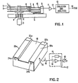
- FIG. 1 shows magnetic discs 1 with two coated sides A and B out of a disc pack that is not completely shown. These discs 1 are mounted on a spindle 2, driven by a motor 3. A spindle bearing 4 is contained in a housing 5. With respect to side A of the lowermost disc 1 a slider 6 containing a magnetic head (not shown) is mounted on a suspension 7 and flies over or on the disc respectively upon rotation. Suspension 7 is mounted on an arm 8 which electrically isolated is fixed to a carriage 9 movable on housing 5.
- An electric connection 10 feeds the measured triboelectric current from slider 6 over suspension 7 and arm 8 into an operational amplifier 11.
- an evaluation and analyser circuit 13 is connected to the output 12 of amplifier 11 to the output 12 of amplifier 11.
- This evaluation and analyser circuit 13 allows to evaluate and analyse the measured triboelectric current and in accordance with the present invention gives a saving signal TRIC at its output 14 under circumstances that are described below.
- Fig. 2 shows details of a slider construction in accordance with, for example, US Patent 4 218 715.
- Slider 18 has two rails 20a and 20b, so-called air bearing surfaces, and is sliding by means of an air bearing over disc surface at an operational speed of approximately 3600 rpm.
- the rails 20a and 20b each start at their leading portion with respect to a moving track of the rotating disc, with a tapered section 22a and 22b respectively.
- At the trailing edge of the slider and at the trailing part of the rails 20a and 20b two thin film magnetic transducer heads 24a and 24b are mounted.
- electric connection 10 is connected at point 16 to the body of slider 18.
- connection 10 is connected to amplifier 11 that has its output 12 leading to evaluation and analysing circuit 13.
- a volt meter 15 to indicate the value of the triboelectric current I flowing between slider 18 and disc surface A of disc 1.
- Fig. 1 only one slider is connected to evaluation and analysing circuit 13. This is sufficient for a complete disc package for the purpose of the present invention. That means that only one head suspension has to be mounted electrically isolated so that triboelectric current I can be measured by a connection fixed to the slider body of one single head.
- This slider 6 in Fig. 1 together with its suspension 7 mounted on arm 8 is moved together with carriage 9 and all other heads in parallel to position the heads over the desired disc tracks.
- the magnetic disc used in that system consists of an aluminium magnesium alloy substrate coated with iron oxide (Fe 2 0a) and aluminium oxide (A1 2 0 3 ) parti- des dispersed in an epoxy recipient.
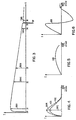
- Fig. 3 shows schematically in a qualitative manner the triboelectric current lover the expected lifetime t of a disc or a disc storage system respectively.
- the triboelectric current I is very much dependent on changes in the disc/slider interface, on the disc surface, on the slider surface and on the lube quantity, quality and distribution.
- slider 6 as shown in Fig 1 is first run-in (conditioned), for example on a first track, and then positioned on another track.
- the triboelectric current I is measured during a testing time in total which is characteristically shown in Fig. 3.
- triboelectric current I around point 30 is about zero and then increases within for example 15 minutes after the start of the test to a maximum threshold value THV1 at point 31. Then afterwards the amplitude of the triboelectric current decreases slowly.
- the estimated lifetime can be defined for instance, by the time when the triboelectric current has decayed to a certain percentage of its maximum value. This might be for example 25% or 10% of the value THV1.
- Fig. 3 there are shown further threshold values beside the maximum threshold value THV1 at timepoint 31, which might be reached after 15 minutes of rubbing test run.
- threshold value THV2 is reached and at timepoint 33 a still smaller threshold value THV3.
- THV4 is reached at timepoint 34.
- a spike SP is shown showing a special phenomena in that the triboelectric current I becomes negative, that means that the flow of the triboelectric current reverses direction.
- a threshold value THV5 is reached. Again this value is on the positive side of the value for the triboelectric current I.
- the curve of Fig. 3 can be measured by extensive tests for example in a measuring time period of 8 hours continuous rubbing contact between slider and disc.
- the height of maximum of the triboelectric current depends on the rotational speed and on the quantity and quality of the lube distributed over the disc.
- To obtain the triboelectric current there must be a frictional, i.e. rubbing contact between disc and slider.
- a rotational speed of 100 and 500 rpm is chosen which results in a flying height of 0-100 nm.
- the curve of Fig. 3 can be measured.
- the result of this measurement for example might be stored in the evaluation and analysing circuit 13 shown in Fig.1 for purposes to be described. In normal operation of a disc storage system such a curve as shown in Fig. 3 cannot be measured.
- the discs When the magnetic disc storage system is not in use the discs do not rotate around its spindle and the magnetic heads are resting on a certain start/stop area of the disc. Upon each start of the magnetic disc storage system the discs are accelerated from 0 rotational speed to a final rotational speed, the so-called operational speed of about 3600 rpm. During a rotational speed up to about 600 rpm the slider and the disc are in rubbing contact. Above that speed up to about 1200 rpm the slider starts to take off from the disc surface and only some occasional rubbing contact is observed.
- Fig. 4 describes for a conditioned track the curves for the triboelectric current I during such a start phase just described. Over the rotational speed n measured in revolutions per minute rpm the triboelectric current I is depicted.
- Curve 431 corresponds to the point 31 in lifetime curve of Fig. 3 and has a threshold value THV1 that is the maximum threshold value and corresponds to threshold value THV1 of Fig. 3.
- THV1 threshold value
- THV1 threshold value
- THV1 threshold value
- Fig. 4 shows with curve 432 another example for the behaviour and value of the triboelectric current I during another start phase and during another timepoint in lifetime of the disc storage system.
- This lifetime might be point 32 of Fig. 3 and the maximum amplitude for the triboelectric current I at that point in time corresponds to threshold value THV2.
- this start-up phase observation shown in Fig. 4 reveals the fact if the triboelectric current I during start phase reaches a certain threshold value. Comparing the maximum threshold value of triboelectric current I against a preset minimum threshold value THVmin gives the possibility to initiate a saving action for the stored data before an irreversible data loss occurs.
- the minimum threshold value THVmin might be preset in accordance with tests for the lifetime of a disc storage system of comparable kind as well as with values that have been found to be representative for the longest possible lifetime in connection with the minimal allowable maximum threshold value for the triboelectric current I during start phase. This is one event against which the triboelectric current I is measured, analysed and compared.
- the saving signal TRIC is generated.
- This signal TRIC is usable to initiate a data saving procedure, either automatically or by intervention of the operator of the system.
- a further possible event in observing the triboelectric current during start- up phases is shown.
- the triboelectric current I is monitored during each start phase if it accepts a negative value, that means if it becomes less than 0 or in other words does flow in a direction opposite to the usually observed current flow direction. This especially might occur at a timepoint 36 shown in Fig. 3 and is depicted with curve 636 in Fig. 6, showing first a positive value and afterwards a negative value for the current I during the start phase. In any case this is also an event which is monitored, and if observed triggers the generation of the saving signal TRIC at output 14 of evaluation and analysing circuit 13.
- This evaluation and analysing circuit 13 can also be used to evaluate a fourth event.
- This fourth possible event is observing the behaviour of the triboelectric current and monitoring the same during the total operation of the disc storage system. If at any point in time during normal operation a triboelectric current occurs this hints at a contact between disc and slider. If those head-disc-interferences occur the danger for irreversible data losses due to destroyed disc surface areas is to be expected. Therefore it is advisable also in those cases to initiate a data saving action. This is possible by generating also in this case the saving signal TRIC.
- the present invention by its method and its device presents the advantage that at different events a saving operation can be initiated before irreversible data losses due to head-disc-interferences occur.
- a saving action can be initiated to prevent irreversible losses of data stored on the monitored magnetic data storage system.
- Those events are: during start phase the triboelectric current should reach a minimum threshold value, should not become negative, i.e. accept a flow direction opposite to the usually observed flow direction, and become 0 at the end of the start phase upon reaching operational speed. Furthermore no triboelectric current should occur during normal operation.
Landscapes
- Supporting Of Heads In Record-Carrier Devices (AREA)
- Recording Or Reproducing By Magnetic Means (AREA)
- Adjustment Of The Magnetic Head Position Track Following On Tapes (AREA)
Description
- The present invention generally relates to magnetic disc storage technology and, more particularly, to a method for monitoring the performance of the interface of a head/slider combination and a magnetic disc, especially a magnetic disc storage system, in which a triboelectric current upon rubbing contact between slider and disc surface is generated. The present invention also pertains to a device for preventing data losses due to head-slid- er/disc interferences in magnetic disc storage systems in which a triboelectric current is observed.
- In magnetic disc storage systems the interface between the combination consisting of the magnetic transducer head and the slider and the surface of the magnetic disc is of great importance. As the slider carries the head and contains air bearing surfaces and slides during normal disc operation on an extremely thin air cushion over the disc surface, the possibility of interferences between head and disc, so-called head disc interferences HDI where the head touches the surface of the disc, cannot be excluded. So HDls are very detrimental both to the slider and its suspension and also to the surface of the disc. This can lead to irreversible damages to the surface of the disc and to the head-slider combination. In both cases irreversible data losses are possible and to be feared.
- In accordance with the applicant's European Patent Application EP-A 203 207 (published after the priority date of the present application) it is described that there exist magnetic storage systems in which a triboelectric current can be observed between the head/slider combination on one side and the surface of the magnetic disc on the other side in case of rubbing contact between these two interface partners. Said application describes a method for measuring and testing the properties of the interface of a slider carrying a magnetic transducer head and a disc in a magnetic disc storage apparatus which is characterized by adjusting the rotational speed of the disc such that there is a rubbing contact between the slider and the disc, in that the thus generated triboelectric current between disc and slider is measured during a measuring/testing period, and in that the amplitude curve of this triboelectric current is analyzed over a time period.
- This known method deals predominantly with the testing of the disc/slider interface and the lifetime testing of magnetic head sliders and/or magnetic disc respectively. This method does not deal with the question of monitoring the performance of the head/slider combination in cooperation with the disc surface in a magnetic disc storage system, especially under the aspect of avoiding data losses due to upcoming head crashes and disc surface destroying events.
- Furthermore in accordance with applicant's European Patent Application EP-A 0 105 094 a method for monitoring the flight of a magnetic transducer head is known. In accordance with this application intermittent contacts between a flying transducer head and a magnetic record medium are monitored by detecting triboelectric charges generated by such contacts. Different amounts and polarities of triboelectric charge are generated by different materials on the surface of the record medium. Furthermore the flight of the head when it is out of contact with the record medium can be monitored by detecting variations in the displacement current generated as the head flies over the record medium. This known method is used to test an assembled disc file to determine the amount of contact between the rotating discs and the associated slider assemblies. And it may also be used to remove any disc which appeared to result in excessive contact with slider assembly.
- As stated in this patent application, detection of both the triboelectric charges generated by contacts between the disc surface and the modulation produced by variations in the spacing between the slider and the disc provides continuous monitoring of both the occurance and severity of such contacts and variations in the spacing when the slider and disc are not in contact.
- This known method deals exclusively with monitoring the triboelectric current or triboelectric charge during the normal operation of a disc system that means when the disc rotates with operational speed. Nothing is stated about the problems involved with start procedures. Furthermore this known prior art does not contain any indication of how data losses could be prevented, what kind of criteria should be applied for preventing those losses and how such action should be initiated and under what circumstances or conditions respectively.
- It is therefore the object of the present invention to provide a method for preventing irreversible data losses in magnetic storage systems due to head/disc interferences such as head crashes and disc surface defects. This method should be able to save the stored data before the storage system is actually destroyed and actual data losses did occur.
- It is another object to provide a device for preventing data losses due to head/slider disc interferences in magnetic disc storage systems in which a triboelectric current is observed to exist between the slider and the disc surface upon rubbing contact between them when in relative motion to each other.
- The invention as laid down in the method and device claims 1 and 6 achieves these objects in advantageous manner. The invention gives the possibility to avoid irreversible data losses of magnetic disc storage systems by monitoring, measuring and analysing the triboelectric current, and based on the analysing results initiating a data transfer shortly before the end of the lifetime of said data storage system. Thus it can be avoided to lose valuable data irreversibly and on the other hand to discard a data storage system earlier than absolutely necessary.
- In the following description of a preferred embodiment of the present invention, the latter is described by means of an example shown in the accompanied drawing in which
- Fig. 1 schematically shows a magnetic disc storage system incorporating the present invention;
- Fig. 2 shows schematically with more detail a slider to which a triboelectric current measuring and indicating device is connected;
- Fig. 3 schematically a plot of the maximum amplitude of the triboelectric current dependent on the lifetime of a disc or a disc storage system respectively;
- Fig. 4 schematically a plot of the triboelectric current dependent upon disc speed during startup phase;
- Fig. 5 schematically a plot of the triboelectric current dependent on the disc speed, with debris collection on headrails during startup phase and
- Fig. 6 schematically a plot of the triboelectric current during startup phase independently of the disc speed for the case of current direction change.
- With reference to Fig. 1 and 2 a set-up in accordance with the invention is schematically depicted. This set-up makes it possible to perform the method in accordance with the present invention. Fig. 1 shows magnetic discs 1 with two coated sides A and B out of a disc pack that is not completely shown. These discs 1 are mounted on a spindle 2, driven by a motor 3. A spindle bearing 4 is contained in a housing 5. With respect to side A of the lowermost disc 1 a
slider 6 containing a magnetic head (not shown) is mounted on a suspension 7 and flies over or on the disc respectively upon rotation. Suspension 7 is mounted on an arm 8 which electrically isolated is fixed to acarriage 9 movable on housing 5. Anelectric connection 10 feeds the measured triboelectric current fromslider 6 over suspension 7 and arm 8 into anoperational amplifier 11. To theoutput 12 ofamplifier 11 an evaluation andanalyser circuit 13 is connected. This evaluation andanalyser circuit 13 allows to evaluate and analyse the measured triboelectric current and in accordance with the present invention gives a saving signal TRIC at itsoutput 14 under circumstances that are described below. - Fig. 2 shows details of a slider construction in accordance with, for example, US Patent 4 218 715.
Slider 18 has tworails rails tapered section 22a and 22b respectively. At the trailing edge of the slider and at the trailing part of therails magnetic transducer heads electric connection 10 is connected atpoint 16 to the body ofslider 18. On theother side connection 10 is connected toamplifier 11 that has itsoutput 12 leading to evaluation and analysingcircuit 13. Furthermore there might be provided avolt meter 15 to indicate the value of the triboelectric current I flowing betweenslider 18 and disc surface A of disc 1. - As can be seen from Fig. 1 only one slider is connected to evaluation and analysing
circuit 13. This is sufficient for a complete disc package for the purpose of the present invention. That means that only one head suspension has to be mounted electrically isolated so that triboelectric current I can be measured by a connection fixed to the slider body of one single head. - This
slider 6 in Fig. 1 together with its suspension 7 mounted on arm 8 is moved together withcarriage 9 and all other heads in parallel to position the heads over the desired disc tracks. - The phenomena of triboelectric current flowing between a slider and a magnetic disc surface upon rubbing contact between both has been observed in a system that comprises a ceramic mixture of aluminium oxide (AI203) and titan carbide (TiC) for the slider. The inclusion of titan
carbide renders slider 6 sufficiently conductive to allow conduction of the triboelectric current. - The magnetic disc used in that system consists of an aluminium magnesium alloy substrate coated with iron oxide (Fe20a) and aluminium oxide (A1203) parti- des dispersed in an epoxy recipient.
- Fig. 3 shows schematically in a qualitative manner the triboelectric current lover the expected lifetime t of a disc or a disc storage system respectively. As described in the European Patent Application EP 85 105 722.4 of applicant's the triboelectric current I is very much dependent on changes in the disc/slider interface, on the disc surface, on the slider surface and on the lube quantity, quality and distribution. To obtain an indication of lifetime of the disc/slider assembly to be expected,
slider 6 as shown in Fig 1 is first run-in (conditioned), for example on a first track, and then positioned on another track. In the presence of good sliding properties the triboelectric current I is measured during a testing time in total which is characteristically shown in Fig. 3. In the very beginning of the lifetime triboelectric current I aroundpoint 30 is about zero and then increases within for example 15 minutes after the start of the test to a maximum threshold value THV1 atpoint 31. Then afterwards the amplitude of the triboelectric current decreases slowly. The estimated lifetime can be defined for instance, by the time when the triboelectric current has decayed to a certain percentage of its maximum value. This might be for example 25% or 10% of the value THV1. - In Fig. 3 there are shown further threshold values beside the maximum threshold value THV1 at
timepoint 31, which might be reached after 15 minutes of rubbing test run. Attimepoint 32 threshold value THV2 is reached and at timepoint 33 a still smaller threshold value THV3. Also a further smaller threshold value THV4 is reached attimepoint 34. At timepoint 35 a spike SP is shown showing a special phenomena in that the triboelectric current I becomes negative, that means that the flow of the triboelectric current reverses direction. Afterwards at timepoint 36 a threshold value THV5 is reached. Again this value is on the positive side of the value for the triboelectric current I. - The curve of Fig. 3 can be measured by extensive tests for example in a measuring time period of 8 hours continuous rubbing contact between slider and disc. The height of maximum of the triboelectric current depends on the rotational speed and on the quantity and quality of the lube distributed over the disc. To obtain the triboelectric current, there must be a frictional, i.e. rubbing contact between disc and slider. For this purpose a rotational speed of 100 and 500 rpm is chosen which results in a flying height of 0-100 nm. Under these set conditions the curve of Fig. 3 can be measured. The result of this measurement for example might be stored in the evaluation and analysing
circuit 13 shown in Fig.1 for purposes to be described. In normal operation of a disc storage system such a curve as shown in Fig. 3 cannot be measured. - In normal operation of a magnetic disc storage system that is provided with the set-up shown in Fig. 1 and 2 upon each start phase of the disc storage and during operation the triboelectric current I can be measured and observed.
- When the magnetic disc storage system is not in use the discs do not rotate around its spindle and the magnetic heads are resting on a certain start/stop area of the disc. Upon each start of the magnetic disc storage system the discs are accelerated from 0 rotational speed to a final rotational speed, the so-called operational speed of about 3600 rpm. During a rotational speed up to about 600 rpm the slider and the disc are in rubbing contact. Above that speed up to about 1200 rpm the slider starts to take off from the disc surface and only some occasional rubbing contact is observed.
- Fig. 4 describes for a conditioned track the curves for the triboelectric current I during such a start phase just described. Over the rotational speed n measured in revolutions per minute rpm the triboelectric current I is depicted.
Curve 431 corresponds to thepoint 31 in lifetime curve of Fig. 3 and has a threshold value THV1 that is the maximum threshold value and corresponds to threshold value THV1 of Fig. 3. Ascurve 431 shows the triboelectric current increases dependent on the rotational speed with increasing speed to the shown maximum value THV1 and then afterwards decreases with increasing rotational speed. At an operational speed of about 3600 rpm the triboelectric current I is 0. It also has to be 0 then because at that operational speed there should be no contact between slider and disc and therefore there should be no triboelectric current present. - Fig. 4 shows with
curve 432 another example for the behaviour and value of the triboelectric current I during another start phase and during another timepoint in lifetime of the disc storage system. This lifetime might bepoint 32 of Fig. 3 and the maximum amplitude for the triboelectric current I at that point in time corresponds to threshold value THV2. - In accordance with one embodiment of the present invention this start-up phase observation shown in Fig. 4 reveals the fact if the triboelectric current I during start phase reaches a certain threshold value. Comparing the maximum threshold value of triboelectric current I against a preset minimum threshold value THVmin gives the possibility to initiate a saving action for the stored data before an irreversible data loss occurs. The minimum threshold value THVmin might be preset in accordance with tests for the lifetime of a disc storage system of comparable kind as well as with values that have been found to be representative for the longest possible lifetime in connection with the minimal allowable maximum threshold value for the triboelectric current I during start phase. This is one event against which the triboelectric current I is measured, analysed and compared. If this comparison shows that the maximum value reached for the triboelectric current I during a specific start phase is smaller than the preset minimum threshold value, then at the
output 14 of the evaluation andanalyser circuit 13 of Fig. 1 the saving signal TRIC is generated. This signal TRIC is usable to initiate a data saving procedure, either automatically or by intervention of the operator of the system. - In connection with Fig. 5 there is described another event which in connection with another embodiment of the present invention is used to generate the saving signal TRIC. If there is a massive accumulation of debris at the rails of the slider, there might be a constant contact between this slider and the disc surface even at operational speed of 3600 rpm. In this case triboelectric current I is flowing and can be measured. That means as shown with
curve 536 in Fig. 5 current I does not become 0 at operational speed of 3600 rpm. That means that the triboelectric current does not disappear at operational speed and in the start phase has not diminished toward 0. This is a clear indication that there is contact between slider and disc during operation of the disc storage. That also means furtheron that at operational speed on the disc surface a rubbing slider most probably destroys the disc surface underneath it. This is a further event for initiating the saving action by generating the saving signal TRIC atoutput 14 of evaluation andanalyser circuit 13. - In connection with Fig. 6 a further possible event in observing the triboelectric current during start- up phases is shown. The triboelectric current I is monitored during each start phase if it accepts a negative value, that means if it becomes less than 0 or in other words does flow in a direction opposite to the usually observed current flow direction. This especially might occur at a
timepoint 36 shown in Fig. 3 and is depicted withcurve 636 in Fig. 6, showing first a positive value and afterwards a negative value for the current I during the start phase. In any case this is also an event which is monitored, and if observed triggers the generation of the saving signal TRIC atoutput 14 of evaluation and analysingcircuit 13. - This evaluation and analysing
circuit 13 can also be used to evaluate a fourth event. This fourth possible event is observing the behaviour of the triboelectric current and monitoring the same during the total operation of the disc storage system. If at any point in time during normal operation a triboelectric current occurs this hints at a contact between disc and slider. If those head-disc-interferences occur the danger for irreversible data losses due to destroyed disc surface areas is to be expected. Therefore it is advisable also in those cases to initiate a data saving action. This is possible by generating also in this case the saving signal TRIC. - The present invention by its method and its device presents the advantage that at different events a saving operation can be initiated before irreversible data losses due to head-disc-interferences occur. By measuring, monitoring, evaluating and analysing the triboelectric current that flows under certain circumstances between a magnetic head slider and the disc surface, a saving action can be initiated to prevent irreversible losses of data stored on the monitored magnetic data storage system. Those events are: during start phase the triboelectric current should reach a minimum threshold value, should not become negative, i.e. accept a flow direction opposite to the usually observed flow direction, and become 0 at the end of the start phase upon reaching operational speed. Furthermore no triboelectric current should occur during normal operation.
Claims (10)
Priority Applications (4)
| Application Number | Priority Date | Filing Date | Title |
|---|---|---|---|
| DE8686104599T DE3669060D1 (en) | 1986-04-04 | 1986-04-04 | WORK MONITORING METHOD OF A HEADPLATE SEPARATION SURFACE AND DEVICE FOR PREVENTING DATA LOSSES DUE TO HEADPLATE INTERFERENCES. |
| EP86104599A EP0248092B1 (en) | 1986-04-04 | 1986-04-04 | Method for monitoring the performance of the head-disc-interface and device for preventing data losses due to magnetic head-disc-interferences |
| JP62035951A JPS62234266A (en) | 1986-04-04 | 1987-02-20 | Data damage preventor for magnetic disc |
| US07/033,384 US4795981A (en) | 1986-04-04 | 1987-03-31 | Method for monitoring the performance of the head-disk-interface and device for preventing data losses due to magnetic head-disk-interferences |
Applications Claiming Priority (1)
| Application Number | Priority Date | Filing Date | Title |
|---|---|---|---|
| EP86104599A EP0248092B1 (en) | 1986-04-04 | 1986-04-04 | Method for monitoring the performance of the head-disc-interface and device for preventing data losses due to magnetic head-disc-interferences |
Publications (2)
| Publication Number | Publication Date |
|---|---|
| EP0248092A1 EP0248092A1 (en) | 1987-12-09 |
| EP0248092B1 true EP0248092B1 (en) | 1990-02-14 |
Family
ID=8195040
Family Applications (1)
| Application Number | Title | Priority Date | Filing Date |
|---|---|---|---|
| EP86104599A Expired EP0248092B1 (en) | 1986-04-04 | 1986-04-04 | Method for monitoring the performance of the head-disc-interface and device for preventing data losses due to magnetic head-disc-interferences |
Country Status (4)
| Country | Link |
|---|---|
| US (1) | US4795981A (en) |
| EP (1) | EP0248092B1 (en) |
| JP (1) | JPS62234266A (en) |
| DE (1) | DE3669060D1 (en) |
Families Citing this family (10)
| Publication number | Priority date | Publication date | Assignee | Title |
|---|---|---|---|---|
| US4872071A (en) * | 1988-01-14 | 1989-10-03 | International Business Machines Corporation | Method and apparatus for detecting abnormal operation of moving storage apparatus |
| US5038625A (en) * | 1989-01-31 | 1991-08-13 | Seagate Technology, Inc. | Tribological head-disk interface testing system |
| US5168412A (en) * | 1989-06-28 | 1992-12-01 | Toan Doan | Surface interference detector |
| US5305165A (en) * | 1991-12-24 | 1994-04-19 | International Business Machines Corporation | Tribo-attractive contact data storage system |
| US5339702A (en) * | 1992-12-24 | 1994-08-23 | Read-Rite Corporation | Test fixture for air bearing magnetic head suspension assembly |
| DE4330051C2 (en) * | 1993-09-06 | 1997-01-23 | Wilfried Restle | Method and arrangement for significantly increasing the life and recording density of magnetic disk memories |
| US6032262A (en) * | 1995-04-18 | 2000-02-29 | Emc Corporation | Disk drive reliability determination system and method |
| US5880587A (en) * | 1997-02-03 | 1999-03-09 | International Business Machines Corporation | Method and apparatus for performing in file slider take-off measurements through tuned external AE detection |
| US8139306B2 (en) * | 2004-02-09 | 2012-03-20 | Sae Magnetics (Hk) Ltd. | Electrical current as probe for modulation at head-disk interface |
| US7965459B2 (en) * | 2008-12-18 | 2011-06-21 | Seagate Technology Llc | Wavelets-based detection of proximity between a sensor and an object |
Family Cites Families (9)
| Publication number | Priority date | Publication date | Assignee | Title |
|---|---|---|---|---|
| US3329943A (en) * | 1963-02-08 | 1967-07-04 | Burroughs Corp | Head-to-disk separation detector |
| US3560946A (en) * | 1968-01-03 | 1971-02-02 | Sperry Rand Corp | Rotating-head memory system utilizing non-contacting flexible record member |
| US3634835A (en) * | 1970-01-09 | 1972-01-11 | Burroughs Corp | Storage system having a head assembly for reading and writing on a record member having a touch indicator circuit |
| JPS5760566A (en) * | 1980-09-29 | 1982-04-12 | Fujitsu Ltd | Magnetic head device |
| JPS58224469A (en) * | 1982-06-21 | 1983-12-26 | Fujitsu Ltd | Method for detecting sliding of magnetic head |
| US4479090A (en) * | 1982-09-30 | 1984-10-23 | International Business Machines Corporation | Circuitry for measuring magnetic head flying characteristics |
| US4532802A (en) * | 1984-05-31 | 1985-08-06 | International Business Machines Corporation | Apparatus for analyzing the interface between a recording disk and a read-write head |
| US4635139A (en) * | 1985-08-26 | 1987-01-06 | International Business Machines Corporation | Asperity burst writer |
| JPH1177A (en) * | 1997-06-10 | 1999-01-06 | Yamaha Motor Co Ltd | Automatic feeding machine |
-
1986
- 1986-04-04 DE DE8686104599T patent/DE3669060D1/en not_active Expired - Lifetime
- 1986-04-04 EP EP86104599A patent/EP0248092B1/en not_active Expired
-
1987
- 1987-02-20 JP JP62035951A patent/JPS62234266A/en active Granted
- 1987-03-31 US US07/033,384 patent/US4795981A/en not_active Expired - Fee Related
Also Published As
| Publication number | Publication date |
|---|---|
| US4795981A (en) | 1989-01-03 |
| DE3669060D1 (en) | 1990-03-22 |
| EP0248092A1 (en) | 1987-12-09 |
| JPH0323989B2 (en) | 1991-04-02 |
| JPS62234266A (en) | 1987-10-14 |
Similar Documents
| Publication | Publication Date | Title |
|---|---|---|
| US6417981B1 (en) | System and method for measuring absolute transducer-medium clearance using a thermal response of an MR transducer | |
| US5742446A (en) | Method for detection of slider-disk contact | |
| EP0804793B1 (en) | Fm detection of slider-disk interface | |
| EP0248092B1 (en) | Method for monitoring the performance of the head-disc-interface and device for preventing data losses due to magnetic head-disc-interferences | |
| US6771440B2 (en) | Adaptive event-based predictive failure analysis measurements in a hard disk drive | |
| US6019503A (en) | Method for identifying surface conditions of a moving medium | |
| US6853508B2 (en) | In-situ detection of contaminant accumulation on a slider in a disk drive | |
| EP0804794B1 (en) | Non-destructive in-situ landing velocity determination of magnetic rigid disk drives | |
| US6239936B1 (en) | Method and apparatus for calibrating a thermal response of a magnetoresistive element | |
| US20060215309A1 (en) | Low flying head detection using readback signal amplitude modulation | |
| US4479090A (en) | Circuitry for measuring magnetic head flying characteristics | |
| WO1996022596A9 (en) | Non-destructive in-situ landing velocity determination of magnetic rigid disk drives | |
| US6094973A (en) | Method and apparatus for mechanical screening of magnetic recording disk drives | |
| US4724392A (en) | System for testing magnetic head/disk interfaces | |
| KR100237283B1 (en) | Method and apparatus for detecting degradation of spindle motor performance in data storage systems | |
| Fu et al. | Readback signal decrease due to dynamic load head-disk contacts | |
| US6112582A (en) | Glide head apparatus for testing recording media | |
| EP0211099A1 (en) | Method for lowering the frictional coefficient of the magnetic head-disk interface in a lubricated magnetic disk system and disk storage system | |
| JP2551951B2 (en) | Floating dust collection method for storage disk device | |
| US7113354B2 (en) | Media noise low-fly height test for a disc drive | |
| Anderson et al. | Effect of environment on drop-outs in rotary head—tape drives | |
| Suk | Effect of tribocharging on lubricant redistribution | |
| JPH0612630A (en) | Sliding test method for magnetic disk and magnetic head | |
| COUDERT et al. | Durability test and damage evaluation of hard disks | |
| Peck et al. | Acoustic emission analysis during high velocity accelerated wear test |
Legal Events
| Date | Code | Title | Description |
|---|---|---|---|
| PUAI | Public reference made under article 153(3) epc to a published international application that has entered the european phase |
Free format text: ORIGINAL CODE: 0009012 |
|
| 17P | Request for examination filed |
Effective date: 19870224 |
|
| AK | Designated contracting states |
Kind code of ref document: A1 Designated state(s): DE FR GB IT |
|
| 17Q | First examination report despatched |
Effective date: 19880225 |
|
| GRAA | (expected) grant |
Free format text: ORIGINAL CODE: 0009210 |
|
| AK | Designated contracting states |
Kind code of ref document: B1 Designated state(s): DE FR GB IT |
|
| PG25 | Lapsed in a contracting state [announced via postgrant information from national office to epo] |
Ref country code: IT Free format text: LAPSE BECAUSE OF FAILURE TO SUBMIT A TRANSLATION OF THE DESCRIPTION OR TO PAY THE FEE WITHIN THE PRESCRIBED TIME-LIMIT;WARNING: LAPSES OF ITALIAN PATENTS WITH EFFECTIVE DATE BEFORE 2007 MAY HAVE OCCURRED AT ANY TIME BEFORE 2007. THE CORRECT EFFECTIVE DATE MAY BE DIFFERENT FROM THE ONE RECORDED. Effective date: 19900214 |
|
| REF | Corresponds to: |
Ref document number: 3669060 Country of ref document: DE Date of ref document: 19900322 |
|
| ET | Fr: translation filed | ||
| PLBE | No opposition filed within time limit |
Free format text: ORIGINAL CODE: 0009261 |
|
| STAA | Information on the status of an ep patent application or granted ep patent |
Free format text: STATUS: NO OPPOSITION FILED WITHIN TIME LIMIT |
|
| 26N | No opposition filed | ||
| PGFP | Annual fee paid to national office [announced via postgrant information from national office to epo] |
Ref country code: GB Payment date: 19930324 Year of fee payment: 8 |
|
| PGFP | Annual fee paid to national office [announced via postgrant information from national office to epo] |
Ref country code: FR Payment date: 19930330 Year of fee payment: 8 |
|
| PGFP | Annual fee paid to national office [announced via postgrant information from national office to epo] |
Ref country code: DE Payment date: 19930428 Year of fee payment: 8 |
|
| PG25 | Lapsed in a contracting state [announced via postgrant information from national office to epo] |
Ref country code: GB Effective date: 19940404 |
|
| GBPC | Gb: european patent ceased through non-payment of renewal fee |
Effective date: 19940404 |
|
| PG25 | Lapsed in a contracting state [announced via postgrant information from national office to epo] |
Ref country code: FR Effective date: 19941229 |
|
| PG25 | Lapsed in a contracting state [announced via postgrant information from national office to epo] |
Ref country code: DE Effective date: 19950103 |
|
| REG | Reference to a national code |
Ref country code: FR Ref legal event code: ST |