EP0247925B1 - Procédé pour pressuriser un câble de télécommunication et dispositif pour la mise en oeuvre de ce procédé - Google Patents
Procédé pour pressuriser un câble de télécommunication et dispositif pour la mise en oeuvre de ce procédé Download PDFInfo
- Publication number
- EP0247925B1 EP0247925B1 EP19870401100 EP87401100A EP0247925B1 EP 0247925 B1 EP0247925 B1 EP 0247925B1 EP 19870401100 EP19870401100 EP 19870401100 EP 87401100 A EP87401100 A EP 87401100A EP 0247925 B1 EP0247925 B1 EP 0247925B1
- Authority
- EP
- European Patent Office
- Prior art keywords
- housing
- sheath
- cable
- shells
- orifice
- Prior art date
- Legal status (The legal status is an assumption and is not a legal conclusion. Google has not performed a legal analysis and makes no representation as to the accuracy of the status listed.)
- Expired - Lifetime
Links
- 238000000034 method Methods 0.000 title claims description 16
- 239000000463 material Substances 0.000 claims description 20
- 239000011347 resin Substances 0.000 claims description 12
- 229920005989 resin Polymers 0.000 claims description 12
- 229920001187 thermosetting polymer Polymers 0.000 claims description 8
- 238000007789 sealing Methods 0.000 claims description 7
- 238000004891 communication Methods 0.000 claims description 6
- 238000002347 injection Methods 0.000 claims description 5
- 239000007924 injection Substances 0.000 claims description 5
- 229920005830 Polyurethane Foam Polymers 0.000 claims description 4
- 239000011496 polyurethane foam Substances 0.000 claims description 4
- 239000013521 mastic Substances 0.000 claims description 3
- 239000006261 foam material Substances 0.000 claims description 2
- 239000000945 filler Substances 0.000 claims 1
- 229920000728 polyester Polymers 0.000 claims 1
- 239000013307 optical fiber Substances 0.000 description 6
- 239000000835 fiber Substances 0.000 description 3
- 239000002984 plastic foam Substances 0.000 description 3
- 239000006260 foam Substances 0.000 description 2
- 229920001225 polyester resin Polymers 0.000 description 2
- 239000004645 polyester resin Substances 0.000 description 2
- 238000004804 winding Methods 0.000 description 2
- 239000004831 Hot glue Substances 0.000 description 1
- 239000000654 additive Substances 0.000 description 1
- 230000005540 biological transmission Effects 0.000 description 1
- 239000004020 conductor Substances 0.000 description 1
- 230000006866 deterioration Effects 0.000 description 1
- 239000002654 heat shrinkable material Substances 0.000 description 1
- 238000010438 heat treatment Methods 0.000 description 1
- 239000004033 plastic Substances 0.000 description 1
- 229920003023 plastic Polymers 0.000 description 1
- 230000000135 prohibitive effect Effects 0.000 description 1
- 230000001681 protective effect Effects 0.000 description 1
- 230000008439 repair process Effects 0.000 description 1
- 239000003566 sealing material Substances 0.000 description 1
- 230000035939 shock Effects 0.000 description 1
- 239000000243 solution Substances 0.000 description 1
Images
Classifications
-
- H—ELECTRICITY
- H02—GENERATION; CONVERSION OR DISTRIBUTION OF ELECTRIC POWER
- H02G—INSTALLATION OF ELECTRIC CABLES OR LINES, OR OF COMBINED OPTICAL AND ELECTRIC CABLES OR LINES
- H02G15/00—Cable fittings
- H02G15/20—Cable fittings for cables filled with or surrounded by gas or oil
- H02G15/26—Expansion vessels; Locking heads; Auxiliary pipe-lines
-
- H—ELECTRICITY
- H02—GENERATION; CONVERSION OR DISTRIBUTION OF ELECTRIC POWER
- H02G—INSTALLATION OF ELECTRIC CABLES OR LINES, OR OF COMBINED OPTICAL AND ELECTRIC CABLES OR LINES
- H02G15/00—Cable fittings
- H02G15/08—Cable junctions
- H02G15/10—Cable junctions protected by boxes, e.g. by distribution, connection or junction boxes
- H02G15/117—Cable junctions protected by boxes, e.g. by distribution, connection or junction boxes for multiconductor cables
Definitions
- the present invention relates to a method for enclosing a gaseous medium under pressure inside the sheath of a telecommunication cable and also relates to a device for carrying out the implementation of this method.
- the invention also extends to cables of this kind, where the pressurization of their sheath is carried out in accordance with the method.
- the supply valves are generally mounted on a cuff of a heat-shrinkable material, surrounding the sheath of the cable in line with a communication passage provided therein, this cuff which has a slot to allow its mounting on a cable already laid, then being shrunk on the sheath using the flame of a torch and / or a hot air gun.
- This cuff which has a slot to allow its mounting on a cable already laid, then being shrunk on the sheath using the flame of a torch and / or a hot air gun.
- the retraction of the cuff on the cable sheath allows sealing between these two elements, the valve then communicating with the interior of the cable through the passage provided in its sheath.
- a hot-melt adhesive coats the internal face of the cuff and is softened during the heating operation thereof, which ensures good adhesion between the cuff and the outer sheath of the cable.
- the present invention relates to a method for pressurizing a telecommunication cable which avoids these drawbacks, by eliminating any brutal heat supply by a torch or other similar device, while ensuring in a safe, rapid and inexpensive manner the sealed connection between a inlet valve for a gaseous presurization medium and the sheath of the cable to be pressurized.
- the process considered for pressurizing with a gaseous medium the external sheath of a telecommunication cable comprising a passage orifice to be connected with an inlet valve for this gaseous medium is characterized in that that it consists in surrounding the cable with a waterproof case provided in its wall of the intake valve and delimiting around the cable a sealed annular housing communicating with the interior of the cable through the passage orifice, the valve being disposed substantially in line with this orifice, to be mounted in the housing between the sheath of the cable and against the inner surface of this housing an elastic cushion having a transverse conduit pierced in its thickness to connect the valve and the orifice, then to inject into the housing outside the elastic cushion and around the sheath a filling thermosetting sealing material.
- thermosetting material in particular of the kind of a polymerizable resin, such that, after hardening of this material, is formed around the cable a rigid and waterproof block, the foam cushion preventing the injection of resin from coming into the provided conduit through this cushion and which communicates the orifice of the sheath and the intake valve.
- the cable pressurization can be carried out without the implementation of the method of the invention requiring any external heat input, the resin injected into the housing surrounding the sheath can be hardened at room temperature or, in any case, with a relatively limited external supply of calories, never exceeding the threshold beyond which the optical fibers constituting the cable would risk being damaged and even more seriously deteriorated.
- the invention also relates to a device for implementing the method specified above, characterized in that it comprises a closed housing produced by means of two shells capable of delimiting a housing around the outer sheath of the cable to be pressurized with a gaseous medium, this housing comprising two bottoms made of a flexible material, parallel and precut for the passage of the sheath in the housing of the housing by coming to bear on it sealingly, an inlet valve mounted in the wall of one of the shells facing the orifice provided in the sheath, an elastic cushion mounted in the housing in sealed abutment on the one hand against the inner surface of the bearing shell the valve and on the other hand against the external surface of the sheath, this cushion having a through conduit communicating the valve and the orifice of the sheath, and at least one vent formed in the wall of one of the shells for the injection and filling of the housing formed from the housing, the bottoms, the sheath and the external surface of the elastic cushion, with a thermosetting material.
- the injected material for filling the housing is a polymerizable resin, of the polyester resin or other type.
- the two shells of the housing each have external lateral flanges, able to come in pairs bearing one against the other when the two shells surround the cable, these flanges having in their facing faces a groove suitable for receiving a seal of mastic or the like to ensure the tightness of the housing.
- the flanges of the shells once applied to one another, are clamped by external clips or clips, pinching these flanges from the outside.
- the bottoms of the housing and the elastic cushion are made of a closed cell foam material, in particular of polyurethane foam.
- the shell comprising the injection vent of the thermosetting material inside the housing of the housing comprises a second vent, distinct from the first, for the evacuation of the overflow of material after filling complete housing.
- a mold is formed in two parts capable of adapting from the outside around the cable, constituting with the external surface of the sheath a closed housing, this mold being placed in place so that the plastic foam cushion it contains ensures, through the conduit passing through, direct communication between the passage orifice formed in the sheath and the intake valve to thereby subsequently authorize the pressurization of the cable .
- the case backs also made of a suitable plastic foam, allow, thanks to their flexibility, to adjust the mounting of the mold with variable cable diameters.
- the clearance between the bottoms and the external surface of the sheath can be filled by one or more windings of a material forming extra thicknesses on the sheath at right of these funds.
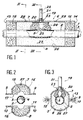
- the reference 1 designates a telecommunication cable comprising, in a manner known per se in the art, an outer sheath 2 made of an appropriate material and whose particular nature is indifferent to the invention, but having d 'In general, sealing properties adapted to allow it to be pressurized with a gaseous medium, in particular dry air.
- the cable 1 contains a bundle 3 of conductive elements, for example a set of optical fibers, schematically designated at 4 in Figure 2.
- the sheath 2 comprises a passage orifice 5 through which the dry air to be introduced into this sheath can be brought in accordance with the provisions of the invention.
- These shells have laterally end flanges 9 and 10 capable, when the two half-shells are applied one on the other around the cable 1, to come into contact, these flanges advantageously having a groove in their opposite faces 11, receiving a seal 12 of mastic or other similar material, ensuring the tightness of the assembly.
- the shells 7 and 8 of the housing 6 also comprise, at each of their ends, bottoms 14 and 15 respectively, made by means of a flexible material, in particular a polyurethane foam or the like, these bottoms having in their edge directed towards the cable 1 a flat lateral part 17 and a pre-cut curved part 18, capable of coming to cover from the outside the external surface of the sheath 2, thus ensuring at the ends of the housing 6 a seal by satisfactory contact.
- a flexible material in particular a polyurethane foam or the like
- a valve 19 for the admission of the gaseous medium to be introduced inside the sheath 2, in particular dry air, supplied by an external generator (not shown).
- This valve 19 of the bicycle valve type or the like has at the end a shoulder 20 applied under the wall of the shell 7 and passes through the latter by a nozzle 21 provided axially with a bore 22 for the passage of air through a valve. (not shown) but of a classic type in itself.
- the immobilization of the valve 19 on the shell 7 is carried out by means of a locking nut 23, cooperating with a threaded part of the end piece 21.
- an elastic cushion 24 is mounted, in a flexible material and preferably also made of polyurethane foam, similar to that which constitutes the bottoms 14 and 15 of the housing, the cushion 24 having a through duct 25, intended for placing in direct communication valve 19 and orifice 5.
- a closed and sealed annular housing 26 into which a thermosetting resin 27, for example of the polyester resin type, can be injected, introduced into the housing by a vent 28 formed in the wall of the shell 7.
- a second vent 29 is provided in the same shell opposite the vent 28 with respect to the valve 19, in order to allow, once the housing 26 has been completely filled with resin 27, evacuation of the possible overflow of this resin.
- a block of hardened resin is thus formed around the elastic cushion 24 itself ensuring the seal between the housing and the external surface of the sheath 2, through which the duct 25 leaves free passage for the dry air to be introduced. under the sheath in order to obtain a suitable pressurization of the cable.
- This operation can then be carried out without at any time having been necessary to involve a supply of calories capable of damaging the conductive elements and in particular the optical fibers of the cable, the curing of the resin being able to take place at room temperature. or, where appropriate, with a reduced temperature rise remaining anyway still far below the threshold where these fibers would suffer harmful damage.
- provision can be made to add rapid setting additives to the resin, further limiting the need for even a limited rise in temperature.
- the invention is not limited to the embodiment more specifically envisaged above and shown in the drawings.
- the device described can be adapted to different cable diameters, either by playing on the flexibility of the case backs which match the cable with a certain adaptability to the shape of the latter, either by creating on this cable at the level of these bottoms extra thicknesses taking up any play, produced with one or more windings of an appropriate plastic material.
Landscapes
- Cable Accessories (AREA)
Applications Claiming Priority (2)
| Application Number | Priority Date | Filing Date | Title |
|---|---|---|---|
| FR8607047A FR2598865B1 (fr) | 1986-05-16 | 1986-05-16 | Procede pour pressuriser un cable de telecommunication et dispositif pour la mise en oeuvre de ce procede. |
| FR8607047 | 1986-05-16 |
Publications (2)
| Publication Number | Publication Date |
|---|---|
| EP0247925A1 EP0247925A1 (fr) | 1987-12-02 |
| EP0247925B1 true EP0247925B1 (fr) | 1991-03-13 |
Family
ID=9335312
Family Applications (1)
| Application Number | Title | Priority Date | Filing Date |
|---|---|---|---|
| EP19870401100 Expired - Lifetime EP0247925B1 (fr) | 1986-05-16 | 1987-05-15 | Procédé pour pressuriser un câble de télécommunication et dispositif pour la mise en oeuvre de ce procédé |
Country Status (3)
| Country | Link |
|---|---|
| EP (1) | EP0247925B1 (es) |
| ES (1) | ES2020672B3 (es) |
| FR (1) | FR2598865B1 (es) |
Family Cites Families (3)
| Publication number | Priority date | Publication date | Assignee | Title |
|---|---|---|---|---|
| US3342056A (en) * | 1963-06-17 | 1967-09-19 | Marvin F Tepner | Compression tool |
| US3564119A (en) * | 1969-11-24 | 1971-02-16 | John T Thompson | Pressure-equalizing accessory for cables |
| DE7702658U1 (de) * | 1977-01-31 | 1977-05-18 | Siemens Ag, 1000 Berlin Und 8000 Muenchen | Befestigung von Kabeleinfüllstuben mittels Schrumpfschlauch |
-
1986
- 1986-05-16 FR FR8607047A patent/FR2598865B1/fr not_active Expired
-
1987
- 1987-05-15 ES ES87401100T patent/ES2020672B3/es not_active Expired - Lifetime
- 1987-05-15 EP EP19870401100 patent/EP0247925B1/fr not_active Expired - Lifetime
Also Published As
| Publication number | Publication date |
|---|---|
| FR2598865A1 (fr) | 1987-11-20 |
| EP0247925A1 (fr) | 1987-12-02 |
| ES2020672B3 (es) | 1991-09-01 |
| FR2598865B1 (fr) | 1988-08-05 |
Similar Documents
| Publication | Publication Date | Title |
|---|---|---|
| FR2683260A1 (fr) | Tube en materiau composite pour forage et/ou transport de produits liquides ou gazeux, en particulier pour l'exploitation petroliere en mer et procede de fabrication d'un tel tube. | |
| EP0039703B1 (fr) | Manchon pour proteger l'epissure de cables electriques ou telephoniques | |
| EP0721246A1 (fr) | Dispositif de fixation, de reprise de masse et d'étanchéité pour câble optique | |
| FR2975164A1 (fr) | Dispositif et procede d'isolation thermique d'une zone de raccordement d'embouts de connexion de deux conduites sous-marines calorifugees. | |
| FR2762455A1 (fr) | Piece de raccordement etanche d'un tube a l'orifice d'une paroi | |
| FR2630196A1 (fr) | Unite d'accumulation de fluide isolee, et notamment chauffe-eau, et procede pour sa fabrication | |
| EP0098765A1 (fr) | Manchon pour protéger l'épissure de câbles électriques ou téléphoniques | |
| FR2771452A1 (fr) | Dispositif de degivrage pour capot d'entree d'air de moteur a reaction | |
| EP0427613B1 (fr) | Dispositif d'étanchéité d'entrée de câble dans un élément de connecteur alvéolaire multicontacts | |
| EP0695900A1 (fr) | Passage étanche pour câble de télécommunications | |
| WO2014106609A1 (fr) | Raccord pour circuit de fibres optiques et procede de connexion d'un tel circuit a un tel raccord | |
| EP0247925A1 (fr) | Procédé pour pressuriser un câble de télécommunication et dispositif pour la mise en oeuvre de ce procédé | |
| EP0234988B1 (fr) | Chambre de combustion de propulseur et son procédé d'assemblage | |
| EP0972103B1 (fr) | Reservoir d'eau pour fer a vapeur, et procede de fabrication d'un tel reservoir | |
| FR2546308A1 (fr) | Traversee etanche pour fibres optiques | |
| CA2032102C (fr) | Dispositif d'etancheite longitudinale pour l'ame d'un cable optique | |
| FR2853710A1 (fr) | Ensemble thermostatique a commande electrique et vanne thermostatique equipee d'un tel ensemble | |
| FR2721088A1 (fr) | Raccord de conduites de carburant comportant un ajutage et un dispositif de son blocage axial dans le perçage de branchement. | |
| CA2033368C (fr) | Ensemble permettant une liaison electrique a travers une conduite formee de plusieurs elements | |
| WO2021245183A1 (fr) | Dispositif de confinement d'une fuite de gaz au niveau de l'interface entre un cone isolant ou un joint plat et une bride | |
| FR3135588A1 (fr) | Elément chauffant pour ligne d’échappement | |
| EP0490725B1 (fr) | Dispositif d'obturation d'un passage tubulaire de cable | |
| EP0488895A1 (fr) | Dispositif de protection d'un raccordement de câbles | |
| FR2700197A1 (fr) | Procédé de réalisation d'un bossage sur une canalisation de fluide en matériau composite et bossage ainsi obtenu. | |
| EP4490364A1 (fr) | Connecteur de liaison destine a lier entre eux des premier et second elements d'un ouvrage |
Legal Events
| Date | Code | Title | Description |
|---|---|---|---|
| PUAI | Public reference made under article 153(3) epc to a published international application that has entered the european phase |
Free format text: ORIGINAL CODE: 0009012 |
|
| AK | Designated contracting states |
Kind code of ref document: A1 Designated state(s): ES GB IT |
|
| 17P | Request for examination filed |
Effective date: 19880415 |
|
| 17Q | First examination report despatched |
Effective date: 19900511 |
|
| GRAA | (expected) grant |
Free format text: ORIGINAL CODE: 0009210 |
|
| AK | Designated contracting states |
Kind code of ref document: B1 Designated state(s): ES GB IT |
|
| ITF | It: translation for a ep patent filed | ||
| GBT | Gb: translation of ep patent filed (gb section 77(6)(a)/1977) | ||
| PLBE | No opposition filed within time limit |
Free format text: ORIGINAL CODE: 0009261 |
|
| STAA | Information on the status of an ep patent application or granted ep patent |
Free format text: STATUS: NO OPPOSITION FILED WITHIN TIME LIMIT |
|
| 26N | No opposition filed | ||
| PGFP | Annual fee paid to national office [announced via postgrant information from national office to epo] |
Ref country code: ES Payment date: 19920423 Year of fee payment: 6 |
|
| PGFP | Annual fee paid to national office [announced via postgrant information from national office to epo] |
Ref country code: GB Payment date: 19920428 Year of fee payment: 6 |
|
| PG25 | Lapsed in a contracting state [announced via postgrant information from national office to epo] |
Ref country code: GB Effective date: 19930515 |
|
| PG25 | Lapsed in a contracting state [announced via postgrant information from national office to epo] |
Ref country code: ES Free format text: LAPSE BECAUSE OF NON-PAYMENT OF DUE FEES Effective date: 19930517 |
|
| GBPC | Gb: european patent ceased through non-payment of renewal fee |
Effective date: 19930515 |
|
| REG | Reference to a national code |
Ref country code: ES Ref legal event code: FD2A Effective date: 19990301 |
|
| PG25 | Lapsed in a contracting state [announced via postgrant information from national office to epo] |
Ref country code: IT Free format text: LAPSE BECAUSE OF NON-PAYMENT OF DUE FEES;WARNING: LAPSES OF ITALIAN PATENTS WITH EFFECTIVE DATE BEFORE 2007 MAY HAVE OCCURRED AT ANY TIME BEFORE 2007. THE CORRECT EFFECTIVE DATE MAY BE DIFFERENT FROM THE ONE RECORDED. Effective date: 20050515 |