EP0247857A2 - Maschine mit Drehventilen und Kraft- und Aufladungssektionen in Tandemverband - Google Patents
Maschine mit Drehventilen und Kraft- und Aufladungssektionen in Tandemverband Download PDFInfo
- Publication number
- EP0247857A2 EP0247857A2 EP87304700A EP87304700A EP0247857A2 EP 0247857 A2 EP0247857 A2 EP 0247857A2 EP 87304700 A EP87304700 A EP 87304700A EP 87304700 A EP87304700 A EP 87304700A EP 0247857 A2 EP0247857 A2 EP 0247857A2
- Authority
- EP
- European Patent Office
- Prior art keywords
- engine
- cylinders
- power
- cylinder
- supercharger
- Prior art date
- Legal status (The legal status is an assumption and is not a legal conclusion. Google has not performed a legal analysis and makes no representation as to the accuracy of the status listed.)
- Withdrawn
Links
Images


Classifications
-
- F—MECHANICAL ENGINEERING; LIGHTING; HEATING; WEAPONS; BLASTING
- F01—MACHINES OR ENGINES IN GENERAL; ENGINE PLANTS IN GENERAL; STEAM ENGINES
- F01L—CYCLICALLY OPERATING VALVES FOR MACHINES OR ENGINES
- F01L7/00—Rotary or oscillatory slide valve-gear or valve arrangements
- F01L7/02—Rotary or oscillatory slide valve-gear or valve arrangements with cylindrical, sleeve, or part-annularly shaped valves
- F01L7/029—Rotary or oscillatory slide valve-gear or valve arrangements with cylindrical, sleeve, or part-annularly shaped valves having the rotational axis of the valve parallel to the cylinder axis
-
- F—MECHANICAL ENGINEERING; LIGHTING; HEATING; WEAPONS; BLASTING
- F02—COMBUSTION ENGINES; HOT-GAS OR COMBUSTION-PRODUCT ENGINE PLANTS
- F02B—INTERNAL-COMBUSTION PISTON ENGINES; COMBUSTION ENGINES IN GENERAL
- F02B73/00—Combinations of two or more engines, not otherwise provided for
-
- F—MECHANICAL ENGINEERING; LIGHTING; HEATING; WEAPONS; BLASTING
- F02—COMBUSTION ENGINES; HOT-GAS OR COMBUSTION-PRODUCT ENGINE PLANTS
- F02B—INTERNAL-COMBUSTION PISTON ENGINES; COMBUSTION ENGINES IN GENERAL
- F02B1/00—Engines characterised by fuel-air mixture compression
- F02B1/02—Engines characterised by fuel-air mixture compression with positive ignition
- F02B1/04—Engines characterised by fuel-air mixture compression with positive ignition with fuel-air mixture admission into cylinder
-
- F—MECHANICAL ENGINEERING; LIGHTING; HEATING; WEAPONS; BLASTING
- F02—COMBUSTION ENGINES; HOT-GAS OR COMBUSTION-PRODUCT ENGINE PLANTS
- F02B—INTERNAL-COMBUSTION PISTON ENGINES; COMBUSTION ENGINES IN GENERAL
- F02B75/00—Other engines
- F02B75/02—Engines characterised by their cycles, e.g. six-stroke
- F02B2075/022—Engines characterised by their cycles, e.g. six-stroke having less than six strokes per cycle
- F02B2075/027—Engines characterised by their cycles, e.g. six-stroke having less than six strokes per cycle four
-
- F—MECHANICAL ENGINEERING; LIGHTING; HEATING; WEAPONS; BLASTING
- F02—COMBUSTION ENGINES; HOT-GAS OR COMBUSTION-PRODUCT ENGINE PLANTS
- F02B—INTERNAL-COMBUSTION PISTON ENGINES; COMBUSTION ENGINES IN GENERAL
- F02B3/00—Engines characterised by air compression and subsequent fuel addition
- F02B3/06—Engines characterised by air compression and subsequent fuel addition with compression ignition
Definitions
- the present invention relates to an engine configuration of the type described in the applicant's U.S. patents Nos. 4,392,460 and 4,444,161, with certain modifications. Much of the engine technology of the those patents and the applicant's U.S. patent No. 3,581,628 are applicable to the present invention and reference can be made to these patents for additional understanding of the invention.
- the present invention is directed to the type of engine disclosed in the aforementioned patents which employs a plurality of cylinders clustered round a main rotary valve.
- One purpose of the present invention is to provide a supercharger for this type of engine which delivers more air to the cylinder to develop more power, and to improve scavenging of the cylinder.
- Another purpose for this supercharged rotary valve engine is to improve the efficiency of the typical high output internal combustion engine by utilizing the improved high efficiency of a piston type compressor for supplying the power cylinder combustion air.
- the piston compressor unlike a centrifugal compressor, always supplies the right amount of air to the firing cylinders regardless of the engine speed.
- the supercharger derives its advantage from the configuration of the rotary valve which allows supercharger or compressor cylinders to be placed axially in line with the power cylinders and effectively provides a cross head piston or a piston which is driven in tandem with the aligned power cylinder piston.
- the axially aligned supercharger cylinders' design provide great compactness and efficiency, but the combination of the basic engine and rotary valve without supercharger requires only simple modifications to the basic engine in order to permit conversion to a supercharged engine which will provide air at a significantly higher pressure to the power cylinders.
- Supplying air at higher pressure to the power cylinders in order to develop more power and better engine torque characteristics may be accomplished in two ways.
- higher pressure may be achieved by using two of the supercharger cylinders to supply a single power cylinder.
- Such an arrangement works particularly well on a four cycle engine having a cluster of four power cylinders.
- the arrangement can provide greater volume in a single supercharger cylinder which feeds a single power cylinder in a two cycle engine. In this latter case, since the supercharger cylinders are axially in line with the power cylinders and the piston and the supercharger is a cross head piston moving with the power piston, the length of stroke of the piston in the power and supercharger cylinders is the same.
- any increase in volume must be accomplished by increasing the diameter of the supercharger cylinder, i.e., the area of the piston.
- the system lends itself to a pressure regulating system associated with the rotary valve whereby a limit may be set to the supercharged air pressure provided the power cylinder and any excess air automatically vented to the exhaust manifold or to a catalytic converter or to the atmosphere. Fuel injection into the rotary valve power cylinder air intake passage is still able to be accomplished as was done in the applicant's prior inventions.
- the present invention broadly relates to an engine having an engine or cylinder block means providing a plurality of power cylinders having parallel axes, each power cylinder having associated firing means.
- An equal number of supercharger cylinders in the engine or cylinder block means are respectively axially aligned with the power cylinders.
- a central bore through the engine or cylinder block means has an axis parallel to the cylinder axes.
- the central bore has ports into each power cylinder at a common axial level and ports into each supercharger cylinder at another common axial level, respectively, at the end of the cylinder remote from drive means. These ports preferably serve both as intake and exhaust ports into the bore of the cylinders.
- a rotary valve is rotatably supported by the engine or cylinder block means in the central bore.
- the rotary valve provides at least one passageway successively connecting ports of the supercharger cylinders to a source of air during the intake phase of those cylinders. At least one passageway through the rotary valve successively connects ports of each supercharger piston with ports of power cylinders to permit transfer of compressed air to the power cylinders on the intake stroke of the power cylinder. At least one passageway through the rotary valve connects ports of the power cylinders successively to the exhaust.
- the rotary valve also functions as a means of opening and closing the ports which time the intake and exhaust part of the cycle of the power cylinders.
- Drive means connects the pistons and the rotary valve producing reciprocation of the pistons in a predetermined phased sequence and rotation of the rotary valve at one half the crank shaft speed. At least a first pair of said power pistons are in phase and a second pair are 180° out of phase with said first pair.
- the rotary valve is phased so that air flows through at least one passageway to the supercharger cylinders in time to be delivered to the power piston during the intake phase. Its phasing also allows air compressed in the supercharger cylinders to be allowed to pass through at least one passageway into the power cylinders for intake during the intake phase.
- the phasing of the rotating valve also allows products of combustion to be exhausted from the power cylinder ports to the engine exhaust port during the exhaust phase.
- the preferred embodiment provides a four cycle engine in the power section with a two cycle compressor for the supercharger.
- two of the supercharger cylinders are permitted to draw in air from their air intake ports as the pistons are on their down stroke.
- two of those cylinders are connected by a common passageway or port to a single power cylinder whose piston is on its downward intake stroke to receive the compressed air.
- Fuel is preferably sprayed in the rotary valve passage at this time in a gasoline engine. If a Diesel type of system is employed, the fuel is delivered at the proper time in the cylinder.
- a pressure regulating valve means may be provided through the engine or cylinder block and ports communications into the aforesaid common passageway to regulate the pressure of the air going into the power cylinder.
- An exhaust passage in the rotary valve is timed to discharge the exhaust gases from the cylinder as the power piston moves upward.
- Cooling of each power piston is provided through coolant passageways in the cylinder block.
- a spray nozzle means sprays cooling oil onto the underside of the power piston and the cylinder walls. Provision is also made for this cooling oil to be drained to the oil pan.
- the alternative type of engine is typically a two stroke cycle power engine wherein the engine function is completed from intake to exhaust within a single down and up motion of the power piston in the cylinder.
- the output of only one supercharger cylinder feeds one power cylinder.
- the two supercharger piston deliveries are accomplished at the same time; they may or may not be intermingled.
- the intake passageway through the rotary valve functions in the same way, except the compressed air is delivered to the bottom of each power cylinder near the piston bottom dead center, and the exhaust passageway functions in the same way as previously described for a four cycle engine.
- the diameter of the supercharger cylinder is enlarged while in the four cycle case was preferably kept close to the same size as the power cylinder. Enlargement up to several times the area of the power cylinder is possible which allows high pressure, or a greater quantity of air, to be supplied from the supercharger.
- the power cylinder configuration and the use of the rotary valve was taught in the inventor's prior U.S. patent No. 4,392,460.
- the present invention is concerned with improvement on the aforesaid patented invention whereby a supercharger section is added to the power section of the engine.
- the supercharger derives its convenience from the use of in line cylinders in a supercharger section, the crosshead pistons of which, in effect, share common piston rods with the pistons of the power section.
- Crosshead pistons within the supercharger cylinders effect a precompression of air before it is fed to the cylinders of the power section.
- One rotary valve serves both sections and is redesigned to simultaneously direct the air for compression by two of the supercharger cylinders for the intake of a single power cylinder.
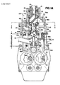
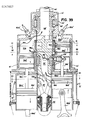
- the power section lies axially above the supercharger section, generally designated 12, in the direction of flow.
- the common rotary valve generally designated 14, extends through both the supercharger and the power sections.
- the rotary valve is provided with an air intake 16 which extends through the walls of the engine block 18.
- the engine or cylinder block may be subdivided into block sections, 20 for the supercharger and 22 for the engine.
- the rotary valve as will be later described, has a Y-branched passageway 24 connecting the air intake to supercharger cylinders, two at a time in the preferred four cycle embodiment illustrated.
- the rotary valve has another Y-branched passageway 26, whose branches are intermediate to those of passageway 26 which connects the discharge of two of the supercharger cylinders with the intake of one of the power cylinders.
- the rotary valve has a power exhaust passageway 28 which is connected to the exhaust of one of the power cylinders at a time.
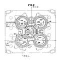
- the power section has four cylinders 30a, 30b, 30c and 30d symmetrically arranged around the rotary valve 14 in central bore 32 of the engine or cylinder block section 22.
- the identical cylinders 30a, 30b, 30c and 30d contain identical pistons 34a, 34b, 34c and 34d.
- Closing the top of each of the cylinders is a common cylinder head 38 which is bolted to the engine or cylinder block 22 and provides bearing means 40 for rotatably supporting the valve and providing an axially aligned exhaust passage, aligned with the valve's exhaust passage 28 and, in turn, aligned with added exhaust pipe connection 44 connected to the head.
- the head also provides each of the cylinders with an intake and exhaust duct 48a, 48b, 48c and 48d which is functionally shaped to direct the intake into the cylinders.
- Each duct effectively contains the compressed gases for firing the particular spark plug 50a, 50b, 50c and 50d located in the duct as shown in each of the power cylinders.
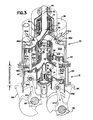
- the rotary valve 14 is also supported within power cylinder block section 22 by needle bearings 52 in Fig. 10.
- the bearings are provided with suitable bearing raceways and cages, if desirable, so that the bearings are not only confined but, in effect, prevent axial movement of the rotary valve while at the same time assuring the valve's smooth rotation.
- seals are employed between the various modular sections, such as between the rotary valve and the block or head portions with which it cooperates.
- the seals confine flow leakage.
- the supercharger cross-section is quite similar to the power section.
- the supercharger section has four cylinders 54a, 54b, 54c and 54d.
- Each cylinder contains a crosshead piston 56a, 56b, 56c, 56d.
- the crosshead pistons are aligned and interconnected with power pistons 34a, 34b, 34c and 34d by piston rods 58a, 58b, 58c and 58d.
- Each of these rods passes through the crosshead top guide holding plate and cylinder head regions 60a, 60b, 60c and 60d through packings 62a, 62b, 62c and 62d, respectively.
- the pistons thus rigidly connected together, move up and down in synchronism in their axially aligned cylinders.
- Driving each of the supercharger pistons is a connecting rod 64a, 64b, 64c and 64d, and crank 66 and 68.
- Connecting rods 64c and 64d are rotatably and eccentrically connected to a common crank shaft 66 and with throws are 180° out of phase.
- Connecting rods 64a and 64b are similarly connected to crank shaft 68.
- FIG. 11 shows graphically, for example, that the power piston 34a is rigidly connected to supercharger piston 56a by piston rod 58a and the two pistons are driven together by connecting rod 64a connected to crank shaft 68.
- pistons 34b and 56b are clearly seen to be 180° out of phase, so that when one set is at the top of its stroke, the other is at the bottom of its stroke.
- pistons 34c and 56c and 34d and 56d are clearly seen to be 180° out of phase.
- crank shafts 66 and 68 are connected to gears 70 and 72, respectively, which cause them to rotate in opposite directions.
- Each crank shaft is arranged such that opposite or alternate pistons are in phase and adjacent pistons are out of phase with one another and the difference in phase between the two sets of pistons is 180°.
- the rotary valve 14 is driven by coaxial bevel gear 74 which meshes with bevel gear 76.
- Suitable gear coupling in the system is provided to insure through bevel gear connections 74 and 76 that the rotary valve 14 is driven in synchronism with the crank shafts but effectively rotates at half the speed of the crank shafts.
- the rotary valve rotates only half a revolution.
- the timing of the gears interconnecting the crank shaft gears is such that the crank shafts make two complete revolutions, and their associated pistons complete two full cycles, for every revolution that the rotary valve makes.
- Gear 74 has an axial shank which preferably is provided with splines for inter-axial engagement with splines within an axial tubular cavity 78 in the gear end of the rotary valve 14 and 80 in Figs. 9 and 10.
- the outer surface of the tubular cavity is also preferably supported on the block portion 20 by another set of bearings and seal 82 in Figs. 1 and 4.
- crank case area 84 is to be of conventional construction so that the detailed discussion of its structure and operation is unnecessary.
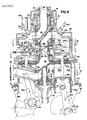
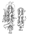
- FIG. 9 shows the cylinder head and portions of the blocks with the actual cylinder areas ignored to better visualize the containment of the rotary valve within its aligned bores. It will be observed in Figs. 1, 1A, 3, 4, 9 and 10 that there are at one axial level in the passageway 26, inter-connecting the supercharger with the power cylinders, a first plurality of ports through the rotary valve wall, Fig. 6, ports 86a, 86b, 86c and 86d. Fig.
- FIG. 4 shows a second plurality of ports 88a, 88b, 88c and 88d through the rotary valve wall lies at a second axial level after the first ports in the direction of flow. These openings allow fuel to be injected into passageway 26.
- the ports 86a, 86b, 86c and 86d are at the level of a cylindrical valve duct 90 arranged generally radially to the rotary valve and extending through the wall of block section 22.
- Duct port 96 provides a ring valve seat 91 and a movable valve 92 supported by the block 22 on stem 94. The valve is open as shown in Fig. 1 or closed as shown in Fig. 6 in accordance with adjustment through valve stem 94.
- Valve channel 96 opens at right angles into a valve channel 97 through valve seat 98 with which pressure sensitive valve 99 cooperates to regulate the pressure of air delivered from the supercharger.
- Valve 100 is tensioned by spring 102 to allow valve 99 to open upon occurrence of a predetermined pressure which overcomes spring 102 to move the valve 100 away from seat 98.
- the rotary valve as seen in Fig. 10 shows the peripheral cylindrical and end surfaces provided with channels to contain suitable means to provide sealing between the various portions of the rotary valve providing different functions.
- Sealing material may be conventional and seals may be of the type discussed in my U.S. patent No. 4,444,161 of April 24, 1984.
- Fig. 12 shows graphically the cycles of the interconnected power and supercharger cylinders, one plot for each of the cylinders involved.
- the changing position of the rotary valve relative to the engine block and the cylinder ports is the changing position of the rotary valve relative to the engine block and the cylinder ports.
- the rotary valve changes position as a unit so that a particular position placing passageways opposite ports of the power cylinders requires a corresponding position placing passageways opposite ports of the supercharger cylinders, which is repeated rotation after rotation.
- the rotary valve as seen in each section, is moving in the direction of the arrows shown in Figs. 15 and 16. Rotation as viewed in these diagrams is always clockwise looking down onto the valve from the top.
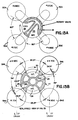
- FIGs. 12A, 12B, 12C and 12D show graphically how two supercharger cylinders, e.g. 54b and 54d, connect to and fill one power cylinder, e.g. cylinder 30a, through the rotary valve 14.
- Figs. 12A, 12B, 12C and 12D together show how successive power cylinders are filled from the specific pair of superchargers as the valve rotates.
- One revolution (360°) of the rotary valve 14 equals two revolutions (720°) of the crank.
- Fig. 13A and 15 represent the exhaust of power cylinder 30a through passageway 28 being completed as that of exhaust from cylinder 30b is begun.
- the rotary valve 14 is just closing the ports in supercharging cylinders 54a and 54c which have just completed compression and hence the discharge from 54a and 54c through passageway 26 into the power cylinder 30d has been almost completed.
- Power cylinder 30d is, therefore, about to be closed off to begin compression of the mixture as the valve 14 rotates.
- the power piston in cylinder 30c is near the top of its compression stroke.
- the energy supplying the force to produce compression in cylinder 30d, as well as power output, is the ignition of the explosive mixture in cylinder 30c by firing spark plug 50c in the duct 48c in Fig.
- cylinders 30a and 30c complete their intake and power strokes, respectively. Because cylinder 30c is being driven down under the explosive force of the mixture in the cylinder which has been ignited, the explosive force needs to be contained or shut off by the rotary valve 14 until that full force of the driving explosion or combustion has been completed. At the same time, the cylinder 30a, as it moves down, draws into it from passageway 26 in the rotary valve the compressed air or air/fuel mixture which is being discharged from supercharger cylinders 54b and 54d. At the same time, cylinders 54a and 54c are drawing in air from the intake through passageway 24 as their supercharger pistons move down.
- Figs. 21 through 26 represent the opposite cycle or phase of movement of the power pistons in the cylinders.
- the pistons 34b and 34d having reached the top of their stroke in cylinders 30b and 30d now begin to move down while the pistons 34a and 34c in cylinders 30a and 30c move up from the bottom position of Fig. 21. Since the supercharger pistons in cylinders 54a and 54c are interconnected with the power pistons in cylinders 30a and 30c, the supercharger pistons also move up and compress the air or air/fuel mixture, ultimately discharging it through passageway 26 to intake power cylinder 30b shown in Figs. 22 to 27.
- Supercharger cylinders 54b and 54d which are compressing Fig. 28 to Fig. 30 are closed for a major part of the upward movement of the pistons and finally open between Fig. 30 and Fig. 31 so that they can together feed their compressed air into passage 26 past the fuel injection means into the power cylinder 30c on its intake stroke shown from Fig. 28 to Fig. 33.
- the other cylinders 54a and 54c which have their supercharger pistons 56a and 56c in downward motion are connected by branches of passage 24 to the intake pipe 16 and are being charged.
- Figs. 27 to 32 repeat Fig. 15 to 20 for the supercharger section of the engine, and repeat its two cycle operations every two strokes of the piston.
- the power section which has four different cycles, repeats every other crank revolution.
- Each power cylinder performs a different function at a different time and does not repeat that function until after four full strokes of the piston, or four cycles of the engine, or two crankshaft revolutions.
- the cylinder which is firing is cylinder 30a.
- the cylinder undergoing compression on its upward stroke is cylinder 30b.
- Cylinder 30c is in intake phase on its downward stroke, and the cylinder 30d is in exhaust phase in its upward stroke.
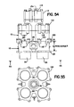
- Figs. 33 through 38 show the final cycle of the four cycle power section wherein cylinder 30b is firing and driving the piston down. Cylinder 30c is undergoing compression. Cylinder 30d is in its intake phase fed by supercharger cylinders 54a and 54c, and cylinder 30a is starting its exhaust phase.
- the air or air/fuel mixture passes from passageway 26 in the rotary valve through intake port 36d into power cylinder 30d with a high speed, helical swirling motion.
- Designing the structure to result in a high pressure spiral swirling motion takes advantage of the resultant forces directing the air fuel mixture as it exits the passageway 26 and enters the intake ports.
- the resultant force is derived from a combination of centrifugal and tangential forces acting on the air or air/fuel mixture in the turbo rotary valve.
- the walls 31a, 31b, 31c and 31d have an angled direction of approach from passageway 26 to each power cylinder.
- the tangential port wall is provided on the right hand side facing the ports.
- the high speed spiral swirl causes the air and fuel to atomize into a lean homogeneous mixture which due to the effect of the piston continues a helical swirling motion down the cylinder during the full intake stroke and spiral swirling up the cylinder during the full compression stroke.
- a lean homogeneous mixture and the high helical swirl are necessary for efficient fast burn combustion.
- the continued high swirling action during ignition and the long power stroke provides an added advantage because of the counterclockwise spiral up the exhaust stroke in which the exhaust gases are centrifugally and tangentially pushed out into the rotating exhaust port causing a rapid and complete expelling of burned gases during the exhaust phase of the four stroke cycle engine.
- the rotary valve is a distributor type of a turbine valve in which the air or air/fuel mixture for the intake phase is fed into the bottom and up through the center part of the valve and feeds intake air or air/fuel mixture into each of the four cylinders consecutively and sequentially as the valve turns at half the crankshaft speed past each of the four cylinder ports.
- the exhaust gases are expelled sequentially in succession through each of the four cylinder ports, one phase ahead of the intake phase, and out the top of the rotary valve.
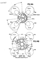
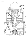
- Figs. 39 through 53 show another embodiment of the present invention wherein an engine is structurally very similar to that shown in Fig. 1, Fig. 5 and Fig. 7, but one designed to be a two cycle engine instead of a four cycle engine.
- the rotary valve 14 ⁇ is considerably modified such that there is a single Y-shaped intake passageway 24 ⁇ and a common, or "X" shaped passageway 26 ⁇ connecting both of a pair of diametrically opposed superchargers to intake ports of a pair of power cylinders.
- the sections of Figs. 39, 40, 41, 42, 43 and 44 illustrate how the rotary valve passageway construction in the two cycle configuration cooperates with the various ports.
- the supercharger section requires an intake passageway 16 ⁇ (Figs. 39 and 40) which simultaneously feeds through the axial passage 24 ⁇ in the crank case end of rotary valve 14 ⁇ into two, opposed in phase, supercharger cylinders, such as 54b ⁇ and 54d ⁇ , as seen in Figs. 39, 40, 43 and 44.
- the power section preferably has an X-shaped rotary valve passageway 26 ⁇ which allows discharge from two supercharger cylinders to supply compressed air or air/fuel mixture to two power cylinders.
- Passageway 28 ⁇ also exhausts from an opposed pair of cylinders using separate exhaust ports 37a and 37c or 37b and 37d at a higher level in the power cylinders 30a ⁇ , 30c ⁇ , 30b ⁇ and 30d ⁇ , than intake ports 35a, 35c, 35b or 35d.
- power cylinders 30a ⁇ , 30c ⁇ , 30b ⁇ and 30d ⁇ are in their initial exhaust cycle stroke, the intake ports 35a, 35c, 35b or 35d are open and supplying air or air/fuel mixture to the power cylinders.
- the parts are so similar in the two embodiments that the same number designators have been applied to corresponding parts, but with the addition of primes to those of Figs. 39 through 53.
- the supercharger cylinders 54a ⁇ , 54b ⁇ , 54c ⁇ and 54d ⁇ instead of being the same size, are larger in diameter than power cylinders 30a ⁇ , 30b ⁇ , 30c ⁇ and 30d ⁇ .
- a supercharger cylinder whose area is twice the area of the power cylinder will provide approximately twice the volume of compressed air or air/fuel mixture which is the equivalent of the volume of two cylinders in the Fig. 1 arrangement.
- any change in cylinder volume to whatever degree designed for a particular system, has to be accomplished by the enlargement of the area of the pistons and or the cross-sectional area of the supercharger cylinder in a situation where effectively two supercharger cylinders feed two power cylinders which are 180° out of phase.
- some increase in volume in some designs is needed in two cycle operations to achieve improved cylinder scavenging and operation by use of a supercharger.
- the power cylinder represents a uniflow cycle where the intake air or air/fuel mixture enters the cylinder at the bottom and the exhaust gases exit at the top of the cylinder.
- the rotary valve 14 ⁇ is made symmetrical and the adjacent ends of the "Y-shaped" passageway 24 ⁇ and "X-shaped” passageway 26 ⁇ are interspersed.
- "Y-shaped” is used in the functional sense of being double branched, and in some cases such a passage might be "T-shaped”.
- an "H-shaped” instead of "X-shaped” passage could be used within the scope of the term. It will, however, be understood that "Y-shaped” means a passageway configuration wherein two ports at the same axial level are fed by branches of the passageway. In all designs, passageways are designed to cause a helical flow to swirl around the cylinder as it enters the intake ports.
- the supercharger cylinders 54a ⁇ , 54b ⁇ , 54c ⁇ and 54d ⁇ have ports 33a, 33b, 33c and 33d, respectively.
- Each of these ports receives input of air from the engine air intake 16 ⁇ through the passage 24 ⁇ . Compressed air is discharged, in turn, from each of these ports into passage 26 ⁇ . At least during part of each quarter rotation of the valve, compressed air is discharged from a pair of opposed cylinders while intake occurs into a pair of opposed cylinders which are 180° out of phase with the first pair.
- Passage 26 ⁇ is preferably X-shaped or H-shaped: that is, it has not only two input branches from the cylinders 54a ⁇ and 54c ⁇ or 54b ⁇ and 54d ⁇ but two output branches to opposed power cylinders 30b ⁇ and 30d ⁇ or 30a ⁇ and 30c ⁇ through input ports 35b and 35d or 35a and 35c. These input ports are just above the lowermost position of the power piston, as illustrated in Fig. 40, in the positions of pistons 34b ⁇ and 34d ⁇ . These input ports 35a, 35b, 35c, 35d are quickly cut off as the pistons move upwardly in a two cycle engine. Exhaust is accomplished through ports 37a, 37c, 37b and 37d, through a branched Y-shaped passage 28 ⁇ which lead to exhaust 44 ⁇ .
- fuel is introduced into passage 26 ⁇ through port 88 ⁇ by fuel injector 106 ⁇ as shown in Fig. 39. Injection is timed so that fuel enters passage 26 ⁇ through lateral ports 88 ⁇ .
- the rotary valve turns at 1/2 engine speed, the same as for the four cycle engine.
- the rotary valve could be designed to turn at engine speed.
- Cylinders are also provided with liners 39a, 39b, 39c and 39d.
- the liners are perforated at the input ports 35a, 35b, 35c and 35d to provide a grid 41a, 41b, 41c and 41d, the bars of which are cut at an angle off radial generally parallel to the average direction of the resultant flow of the air fuel input flow so as to provide fluid directing slots.
- the input port wall toward which flow would be directed is also generally parallel to the average flow direction and arranged tangential to the cylinder wall.
- the curved cylinder wall receives the flow with a minimum of disturbance to generate the high helical swirling motion within the cylinders of air or air/fuel mixture.
- the spiral swirling is in a counterclockwise direction as it flows around the inside of the cylinder (as suggested by the arrows in cylinders 30a ⁇ and 30c ⁇ in Figs. 42 and 45).
- the swirl continues in the cylinders even during compression which causes efficient lean mix, fast burn combustion.
- the piston is driven downwardly.
- the passage 28' is brought into register with the exhaust passages 37a and 37c, as seen in Fig. 41, or with exhaust passages 37b and 37d a quarter of a rotation later.
- the continuing helical swirling motion in the two cycle engine is very similar to the four cycle engine except the intake air is fed into the bottom of two cylinders and flows through vertical guides in a spiral swirling counterclockwise direction. This counterclockwise rotating air helps to force the products of combustion through the exhaust ports at the top of the two cylinders where they meet in the exhaust passageway in the rotary valve and out through the exhaust port on the top of the engine. It is most advantageous during the two cylinder intake and the two cylinder exhaust phases of the two cycle engine in rapidly and completely expelling burned gases through the exhaust ports at the top of the cylinders before the air/fuel mixture is introduced into the cylinder near the bottom of the stroke so that no fuel mixes with the hot exhaust gases before the exhaust port closes.
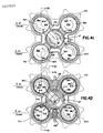
- Fig. 45 diagrams and Figs. 42 and 43 show representative tandem power and supercharger cylinders. Output from compressor 54b ⁇ and 54d ⁇ in Fig. 43 feeds power cylinders 30a ⁇ and 30c ⁇ in Fig. 42 through passageway 26 ⁇ at this particular point in the cycle.
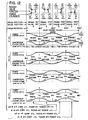
- Figs. 45-1, 45-2 and 45-3 show the relative timing in number of degrees of the intake and exhaust ports rotary valve openings and closings at the power cylinder intake and exhaust port positions as represented by crank angle position in degrees of the opposed cylinders in one rotation of the crank shaft. Only three examples are shown illustrating valve timing variations possible in the valve design, and it will be understood other variations are possible.
- Figs. 46-1, 46-2 and 46-3 correspond to Figs. 45-1, 45-2 and 45-3, respectively, showing variations possible in the design and phasing of the number of degrees of the supercharger valve timing of the intake and exhaust port rotary valve openings and closings in conjunction with changes in the three examples of cylinder port openings.
- Figs. 46-1, 46-2 and 46-3 are views taken at the level of the supercharger ports illustrating valve structure angles and relate to the phasing of the supercharger compressor at discharge relative to the power cylinders to which they are connected at intake. The angles shown give a quantitative idea of the way in which the passages in the valve are timed relative to the ports 33a, 33b, 33c and 33d to regulate phase opening and closing.
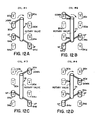
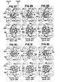
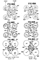
- Figs 47A, 47B, and 47C show, respectively, schematic diagrams representing the three levels of the ports in a two cycle engine rotary valve.
- Fig. 47A is a cross-section taken through power cylinders 30a ⁇ , 30b ⁇ , 30c ⁇ and 30d ⁇ at the level of exhaust port 37a, 37b, 37c and 37d.
- Fig. 47B is a cross-section also through the power cylinders at the level of intake ports 35a, 35b, 35c and 35d, just above the bottom of the piston stroke.
- Fig. 47C is a cross-section taken through the supercharger or compressor cylinders 54a ⁇ , 54b ⁇ , 54c ⁇ and 54d ⁇ at the level of the common ports providing both for intake and discharge.
- FIG. 47A, 47B and 47C are related to the same position of rotary valve 14 ⁇ .
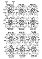
- Figs. 48A, 48B and 48C through 54A, 54B and 54C are all related in the same way as Figs. 47A, 47B and 47C in that figures with common numbers represent the same rotary valve position which is defined by relative piston and valve position angles shown beneath the final figure in each sequence of figures.
- the sequence of three related figures is intended to illustrate consecutive valve positions through the major valve and port cooperation sequences in a cycle.
- Fig. 47A, 47B and 47C show the valve and pistons in an arbitrary position where the piston is in its 160° position (its crank pin position) and the valve is in an 80° position.
- crank (and pistons) move at twice the rotational speed of the rotary valve.
- Figs. 48 through 53 show the rotary valve 14 ⁇ in a sequence representing a half rotation taken in 22 1/2° steps, or 45° steps for the crank shaft. It will be understood that the other half rotation is functionally a mirror image of the half shown and the second cycle is repetitious of the first.
- the two, like the four, cycle system is symmetrical with pistons in opposed cylinders being in phase and those of intermediate cylinders being 180° out of phase.
- the supercharger and the power cylinders in axial alignment are coupled mechanically and maintain the same phase.
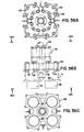
- Figs. 56A, 56B, 56C and 57 illustrate how engine components are assembled into a standard non-supercharged module consisting of the engine block section 10 extending into the crankcase, the cylinder head section 110 and the rotary valve top bearing support section 112.
- the module will be assembled complete with suitable sealing gaskets and all internal components including bearings, seals and rotary valve complete with bevel drive gear.
- the module is intended to be a replacement unit which can quickly be installed in place of a damaged or malfunctioning module with a minimum of time and effort.
- Cranks, connecting rods and pistons are not included in the replacement module.
- These parts are assembled to the crankshafts in the crankcase and remain part of the crankcase and the crankshaft section.
- Figs. 54 and 55 illustrate how engine components are assembled into an engine with a supercharger in accordance with the present invention.
- Figs. 54 and 55 require the tandem pistons internally to complete a supercharged engine.
- the supercharged module consists of the supercharger section 12 extending into the crankcase, the power cylinder block section 10, the cylinder head section 110 and the top bearing support section 112.
- the module will be assembled complete with suitable sealing gaskets and all internal components including bearings, seals, and rotary valve complete with bevel drive gear.
- the supercharged module (like the standard non-supercharged module) is also intended to be a replacement unit which can quickly be installed when necessary. Cranks, connecting rods and tandem pistons are not included in the replacement module. These original parts would be reassembled in the cankcase of the rebuilt engine.
- the various sections of the module are bolted together and are easily separable from each other for easy access to internal structure for repair and maintenance.
- conversion from a standard engine as shown in Figs. 56B and 56C to a supercharged engine as shown in Figs. 54 and 55 is possible with the addition of a supercharger section. Removal of the supercharger section from a supercharged engine to convert a supercharged engine to a standard engine is also possible.
- tandem pistons, a supercharged type rotary valve and associated components are needed for the conversion; however, these along with single pistons, rods, seals, etc. can be stocked for ready conversion.
- the various sections as a practical matter can be stockpiled for use in various combinations of engines.
- the modular construction also allows for replacement of individual sections instead of the whole engine and allows for the stocking of fewer parts to be assembled into engines of different kinds depending upon a particular customer's order.
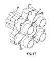
- Fig. 57 shows the modular engine of Figs. 56A, 56B and 56C in perspective and shows how the cylinder walls 54 or 54a, 54b, 54c, and 54d fit down in the crankcase 84 shown in Figs. 1, 1A, 3 and 4. It will, of course, be clear that when the four cycle engine is assembled a modified rotary valve is required for a non-supercharged, as opposed to supercharged, engine omitting the passages interconnecting the supercharger cylinders with the power cylinders. The cylinders 54 in all cases extend below the lowermost section. It will be observed in Fig.
- the power cylinder block section 10 is the block above section 12 used for the supercharger in the structure of Fig. 54. It will be observed in Fig. 54 that the bosses 116 ⁇ similar to bosses 116 provided on block 10 are in position to receive bolts from the cylinder head 110 in the configuration of Fig. 56 and additionally the structure of block 12 is provided with flanges 118 which are needed to cooperate with flanges 120 on block 10 but are unused in the configuration of Fig. 56.
- Figs. 54 through 57 are used in connection with a crankcase 84 of the type illustrated in Figs. 1, 1A, 3 and 4 and the system is further modular in the sense that multiple engine modules can be used with a given crankcase.
- the crankcase shown in Fig. 1, for example, has a removable pin which allows connection of connecting rods and pistons in each of the engine modules on the opposite sides of each of the double crankshaft crankcase sections.
- Fig. 58 a composite engine without a supercharger is illustrated. Although only one crankshaft of the two is shown, it will be understood that in every case two crankshafts must be used.
- Fig. 58 a composite engine without a supercharger is illustrated. Although only one crankshaft of the two is shown, it will be understood that in every case two crankshafts must be used.
- crankshafts 66 and 68 are used. Only two of the four pistons are schematically shown in Figs. 58 through 73 attached to one crank shaft. It will be understood that the other two pistons must be attached to another crank shaft in a balanced fashion.
- Fig. 58 illustrates the simplest configuration of a single module engine 150.
- This one module engine has four cylinders having only power cylinders and four pistons 156a, 156b being shown and pistons 156c and 156d attached to another crank shaft being not shown.
- Pistons 156a and 156b are connected by connecting rods 154a and 154b to crank shaft 152, and the other pistons have a similar configuration.
- a module 151 employing a supercharger is shown.
- the housing is accordingly modified to include a supercharger section in this supercharged engine.
- the piston structure is modified to provide tandem pistons.
- the lower pistons 156a and 156b are supercharger pistons and are connected by piston rods 158a and 158b to power pistons 160a and 160b.
- Fig. 60 shows a composite two module engine structure in which an identical second module 150 ⁇ is attached to the crank case in mirror image position and its pistons are connected to same crank shafts from the opposite side of the crank case.
- Pistons 156e and 156f are connected by connecting rods 154e and 154f to common crank pin bearing locations on crank shaft 152 with connecting rods 154a and 154b of pistons 156a and 156b.
- Pistons 156g and 156h and their separate crank shaft are not shown.
- Fig. 61 shows a two module composite supercharged engine situation in which supercharged engine module 151 is opposed by supercharged engine module 151 ⁇ connected to the same crank shaft as module 151 on the opposite side of the crank case.
- connecting rods 154e and 154a share a common crank pin and as do connecting rods 154f and 154b.
- Fig. 62 shows three engine modules assembled similar to those of Figs. 58 and 60. Couplings are provided between both crank shafts in each of the two crank cases, as illustrated by the coupling 162 between crank shaft 152 and crank shaft 164. Coupling 162 and the other coupling of the engine are external of the crank cases in Figs. 62. Instead of providing a coupling, a common crank shaft may be employed as is shown in the three module supercharged structure of Fig. 63 which effectively combines the subcombinations of Figs. 59 and 61. In Fig. 62, the opposed engine modules are designated 150A and 150A ⁇ and the single unopposed engine unit is designated 150B. In Fig. 63, the opposed engine modules are 151A and 151A ⁇ and the unopposed engine module is 151B.
- Fig. 64 a four module composite engine combines two engines like that of Fig. 60 using external couplings of their crank shafts, such as coupling 162 between shafts 152 and 164.
- the composite engine is similar to Fig. 62 except that module 150B is opposed by a similar module 150B ⁇ in which the connecting rods are connected to the crank shaft 164 at the same crank pin centers.
- Fig. 65 is a similar engine configuration to that of Fig. 64 with a common shaft instead of a coupling 162 between two shafts and with four supercharged modules making up the composite engine.
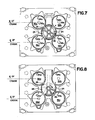
- Figs. 66 and 67 show the five module non-supercharged composite engine and the five module supercharged engine configurations, respectively.
- crank shaft 166 is coupled by external coupling 162 to crank shaft 164.
- Continuous crank shafts are used in composite engine of Fig. 67.
- the shaft sections may employ a coupling 162 between shafts 164 and 166 as in Fig. 68, a six module non-supercharged composite engine.
- continuous shafts 152 are used in Fig. 69, a six module supercharged composite engine.
- crank cases themselves containing the crank shafts and other drive equipment could be consolidated, but part of the advantage is to provide modular construction with some sort of suitable means of coupling the shafts together.
- composite engine combinations such as those using separate crank cases, means of locking the modules and separate crank cases in position relative to one another are necessary and may, for example, be a common mounting frame or chasis.
- the crank cases themselves represent a unifying frame to which engine modules are connected.
- Figs. 70 and 71 show, respectively, seven module non-supercharged and supercharged composite engines.
- Fig. 70 again an additional crank shaft section 168 is externally coupled by coupling 162 to shaft 166 in a non-supercharged engine.
- the composite supercharged engine of Fig. 71 employs continuous crank shafts.
- Figs. 72 and 73 show, respectively, eight module non-supercharged and supercharged composite engines. Again, the composite engine of Fig. 72 uses an external coupling to connect separate shafts, whereas, the shafts of Fig. 73 are continuous.
- the multi-module engines will be very smooth running since the crank cases can be designed to balance out the second harmonic unbalance and in some cases balance out the couples.
- a two stroke cycle and four stroke cycle embodiment of the present invention have been illustrated. It will be clear to those skilled in the art that other embodiments of the invention can readily be made. Variations may take many forms and include such things as cylinders having separate input and output ports, either at the same axial level or a different axial level, or the ports may be located at the top of the cylinders with suitable modification of the rotary valve. Fuel injection means or other fuel introduction means may alternatively be included in each of the cylinders.
- More than four cylinders may be arranged around the rotary valve. Where more power is desired, instead of adding to the number of cylinders around the valve, however, it may be desirable to employ pairs of opposed engines and various composite combinations suggested by those illustrated. Still other modifications include an inverted form of the engine where the power section is placed closer to the crankcase than the supercharger section. Modified rotatable drives may be employed with the rotary valve, some of which might permit axial intake as well as axial exhaust. Alternatively, the exhaust might be led through the engine block like the intake, although the form shown is preferred.
- the timing of the rotary valve may be adjusted by mounting the valve within a sleeve which is adjustable axially and/or circumferentially to optimize the rotary valve port timing for the specific engine operation.
- seals are particularly important to preserve the integrity of the various flows within the engine and to prevent interchange of those flows.
- Pressure regulation may also take many forms, some very much more complex than the ones shown by way of illustration.
- an additional section of superchargers on another axial level could be employed or even a highly efficient turbocharger for greater power boost.
- a whole extended engine having multiple power sections and multiple supercharger sections all with their axially aligned pistons connected together by connecting rods so that pistons in aligned cylinders move in synchronism is also conceivable as a logical extension of the present invention.
Landscapes
- Engineering & Computer Science (AREA)
- Mechanical Engineering (AREA)
- General Engineering & Computer Science (AREA)
- Chemical & Material Sciences (AREA)
- Combustion & Propulsion (AREA)
- Supercharger (AREA)
- Combustion Methods Of Internal-Combustion Engines (AREA)
Applications Claiming Priority (2)
| Application Number | Priority Date | Filing Date | Title |
|---|---|---|---|
| US06/868,305 US4777917A (en) | 1986-05-28 | 1986-05-28 | Rotary valve engine with tandem power and supercharger sections |
| US868305 | 1986-05-28 |
Publications (2)
| Publication Number | Publication Date |
|---|---|
| EP0247857A2 true EP0247857A2 (de) | 1987-12-02 |
| EP0247857A3 EP0247857A3 (de) | 1989-01-18 |
Family
ID=25351413
Family Applications (1)
| Application Number | Title | Priority Date | Filing Date |
|---|---|---|---|
| EP87304700A Withdrawn EP0247857A3 (de) | 1986-05-28 | 1987-05-27 | Maschine mit Drehventilen und Kraft- und Aufladungssektionen in Tandemverband |
Country Status (3)
| Country | Link |
|---|---|
| US (1) | US4777917A (de) |
| EP (1) | EP0247857A3 (de) |
| JP (1) | JPS6375315A (de) |
Cited By (1)
| Publication number | Priority date | Publication date | Assignee | Title |
|---|---|---|---|---|
| DE102008061624A1 (de) * | 2008-12-11 | 2010-07-15 | Arnold Cyliax | 4T2 Motor-Konzeption |
Families Citing this family (4)
| Publication number | Priority date | Publication date | Assignee | Title |
|---|---|---|---|---|
| US5967108A (en) | 1996-09-11 | 1999-10-19 | Kutlucinar; Iskender | Rotary valve system |
| US20110036653A1 (en) * | 2009-08-11 | 2011-02-17 | Clyde Platt | Internal combustion rotary engine with intermeshing rotors |
| US8904987B2 (en) | 2013-04-26 | 2014-12-09 | Gary G. Gebeau | Supercharged engine design |
| US11333140B2 (en) * | 2019-06-11 | 2022-05-17 | Caterpillar Inc. | Cooling block for multi-cylinder air compressor |
Family Cites Families (22)
| Publication number | Priority date | Publication date | Assignee | Title |
|---|---|---|---|---|
| DE241235C (de) * | ||||
| US1510651A (en) * | 1924-10-07 | Supercharging internal-combustion-engine valve mechanism | ||
| US773490A (en) * | 1903-09-25 | 1904-10-25 | Joseph D Ferry | Engine. |
| US1001782A (en) * | 1910-09-17 | 1911-08-29 | Otto C Steglat | Internal-combustion engine. |
| US1361978A (en) * | 1920-03-08 | 1920-12-14 | George John William | Internal-combustion engine |
| US1783018A (en) * | 1924-10-22 | 1930-11-25 | Goetaverken Ab | Gas-generating combustion engine |
| US2101319A (en) * | 1935-03-25 | 1937-12-07 | Robert C Moffitt | Internal combustion engine |
| US2938506A (en) * | 1947-02-19 | 1960-05-31 | Walder Dr Hermann | Reciprocating piston engine type gas generator for gas turbines |
| US2984966A (en) * | 1955-11-04 | 1961-05-23 | Harris Leonard Bushe | Compound internal combustion engine |
| US3288123A (en) * | 1964-07-02 | 1966-11-29 | El Don Corp | Supercharging engine |
| US3581628A (en) * | 1969-12-04 | 1971-06-01 | Thomas V Williams | Inherently balanced reciprocating power plant |
| US4090478A (en) * | 1976-07-26 | 1978-05-23 | Trimble James A | Multiple cylinder sinusoidal engine |
| US4135478A (en) * | 1976-10-20 | 1979-01-23 | Rassey Louis J | Modular engine construction |
| US4198947A (en) * | 1976-10-20 | 1980-04-22 | Rassey Louis J | Modular engine construction |
| DE2656681A1 (de) * | 1976-12-15 | 1978-06-22 | Klaue Hermann | Mehrzylinder-zweitakt-brennkraftmaschine, insbesondere fuer kraftfahrzeuge |
| US4205638A (en) * | 1977-11-18 | 1980-06-03 | Giovanni Vlacancinch | Fluid power supply system |
| US4185597A (en) * | 1978-03-06 | 1980-01-29 | Cinquegrani Vincent J | Self-supercharging dual piston engine apparatus |
| US4279225A (en) * | 1979-04-12 | 1981-07-21 | Kersten Herbert H | Rotary valve engine |
| US4444161A (en) * | 1980-03-21 | 1984-04-24 | Williams Thomas V | Rotary valve for inherently balanced engine |
| US4392460A (en) * | 1980-03-21 | 1983-07-12 | Williams Thomas V | Parallel inherently balanced rotary valve internal combustion engine |
| US4632081A (en) * | 1983-08-01 | 1986-12-30 | Giuliani Robert L | Giuliani modular engine improvement |
| US4610223A (en) * | 1984-09-04 | 1986-09-09 | Paul Karlan | Cam engine |
-
1986
- 1986-05-28 US US06/868,305 patent/US4777917A/en not_active Expired - Fee Related
-
1987
- 1987-05-27 EP EP87304700A patent/EP0247857A3/de not_active Withdrawn
- 1987-05-28 JP JP62130038A patent/JPS6375315A/ja active Pending
Cited By (1)
| Publication number | Priority date | Publication date | Assignee | Title |
|---|---|---|---|---|
| DE102008061624A1 (de) * | 2008-12-11 | 2010-07-15 | Arnold Cyliax | 4T2 Motor-Konzeption |
Also Published As
| Publication number | Publication date |
|---|---|
| JPS6375315A (ja) | 1988-04-05 |
| EP0247857A3 (de) | 1989-01-18 |
| US4777917A (en) | 1988-10-18 |
Similar Documents
| Publication | Publication Date | Title |
|---|---|---|
| EP2171211B1 (de) | Verbrennungsmotor | |
| EP0159320B1 (de) | Verbrennungsmotor und dessen wirkungskreis | |
| US5526778A (en) | Internal combustion engine module or modules having parallel piston rod assemblies actuating oscillating cylinders | |
| US5431130A (en) | Internal combustion engine with stroke specialized cylinders | |
| EP0550044B1 (de) | Nutationsbewegungsbrennkraftmaschine | |
| US4060060A (en) | Valving system for compressors, engines and the like | |
| US4777917A (en) | Rotary valve engine with tandem power and supercharger sections | |
| US6250263B1 (en) | Dual piston cylinder configuration for internal combustion engine | |
| EP0137622A1 (de) | Brennkraftmaschine | |
| US4998511A (en) | Compression ignition engine with variable swept volume | |
| US4586881A (en) | Machine having integral piston and cylinder wall sections | |
| CA1224723A (en) | Rotary engine | |
| US4392460A (en) | Parallel inherently balanced rotary valve internal combustion engine | |
| CN102278198B (zh) | 一种水油混烧旋转发动机 | |
| US3968777A (en) | Internal combustion engine | |
| US4131090A (en) | Two-stroke, multicylinder, spark ignition, pumpless injection internal combustion engine | |
| CN202055913U (zh) | 水油混烧旋转发动机 | |
| EP0776423B1 (de) | Fremdgezündete zweitaktbrennkraftmaschine | |
| CA1324542C (en) | Regenerative thermal engine | |
| US20130118445A1 (en) | Rotary piston engine | |
| AU649622B2 (en) | Toroidal hyper-expansion rotary engine, compressor, expander, pump and method | |
| US788402A (en) | Internal-combustion engine. | |
| GB2076465A (en) | Turbocharged two-stroke engine | |
| US20020050254A1 (en) | Two cycle internal combustion engine | |
| GB2325709A (en) | Combustion-product engine |
Legal Events
| Date | Code | Title | Description |
|---|---|---|---|
| PUAI | Public reference made under article 153(3) epc to a published international application that has entered the european phase |
Free format text: ORIGINAL CODE: 0009012 |
|
| AK | Designated contracting states |
Kind code of ref document: A2 Designated state(s): DE FR GB IT |
|
| PUAL | Search report despatched |
Free format text: ORIGINAL CODE: 0009013 |
|
| AK | Designated contracting states |
Kind code of ref document: A3 Designated state(s): DE FR GB IT |
|
| 17P | Request for examination filed |
Effective date: 19890715 |
|
| 17Q | First examination report despatched |
Effective date: 19891207 |
|
| STAA | Information on the status of an ep patent application or granted ep patent |
Free format text: STATUS: THE APPLICATION IS DEEMED TO BE WITHDRAWN |
|
| 18D | Application deemed to be withdrawn |
Effective date: 19910205 |