EP0247660A2 - Halbleiteranordnung mit einem Bipolartransistor und Feldeffekttransistoren - Google Patents
Halbleiteranordnung mit einem Bipolartransistor und Feldeffekttransistoren Download PDFInfo
- Publication number
- EP0247660A2 EP0247660A2 EP19870200846 EP87200846A EP0247660A2 EP 0247660 A2 EP0247660 A2 EP 0247660A2 EP 19870200846 EP19870200846 EP 19870200846 EP 87200846 A EP87200846 A EP 87200846A EP 0247660 A2 EP0247660 A2 EP 0247660A2
- Authority
- EP
- European Patent Office
- Prior art keywords
- region
- insulated gate
- field effect
- gate field
- effect transistor
- Prior art date
- Legal status (The legal status is an assumption and is not a legal conclusion. Google has not performed a legal analysis and makes no representation as to the accuracy of the status listed.)
- Granted
Links
Images


Classifications
-
- H—ELECTRICITY
- H10—SEMICONDUCTOR DEVICES; ELECTRIC SOLID-STATE DEVICES NOT OTHERWISE PROVIDED FOR
- H10D—INORGANIC ELECTRIC SEMICONDUCTOR DEVICES
- H10D84/00—Integrated devices formed in or on semiconductor substrates that comprise only semiconducting layers, e.g. on Si wafers or on GaAs-on-Si wafers
- H10D84/101—Integrated devices comprising main components and built-in components, e.g. IGBT having built-in freewheel diode
- H10D84/121—BJTs having built-in components
-
- H—ELECTRICITY
- H10—SEMICONDUCTOR DEVICES; ELECTRIC SOLID-STATE DEVICES NOT OTHERWISE PROVIDED FOR
- H10D—INORGANIC ELECTRIC SEMICONDUCTOR DEVICES
- H10D84/00—Integrated devices formed in or on semiconductor substrates that comprise only semiconducting layers, e.g. on Si wafers or on GaAs-on-Si wafers
- H10D84/40—Integrated devices formed in or on semiconductor substrates that comprise only semiconducting layers, e.g. on Si wafers or on GaAs-on-Si wafers characterised by the integration of at least one component covered by groups H10D12/00 or H10D30/00 with at least one component covered by groups H10D10/00 or H10D18/00, e.g. integration of IGFETs with BJTs
- H10D84/401—Combinations of FETs or IGBTs with BJTs
- H10D84/403—Combinations of FETs or IGBTs with BJTs and with one or more of diodes, resistors or capacitors
- H10D84/406—Combinations of FETs or IGBTs with vertical BJTs and with one or more of diodes, resistors or capacitors
Definitions
- EP-A-180255 describes such a semiconductor device in which four insulated gate field effect transistors are integrated and merged with a bipolar transistor.
- the body of the semiconductor device forms the collector regions of the bipolar transistor and islands of the opposite conductivity type are provided adjacent one surface of the semiconductor body forming, alternately, a base region of the bipolar transistor and a drain region of the first insulated gate field effect transistor so that each base region is surrounded by drain regions of the first field effect transistor.
- a single base region having on either side a drain region of the first insulated gate field effect transistor will be considered in the interests of simplicity.
- the first insulated gate field effect transistor has an insulated gate overlying a channel area provided by the body region between the base region and a first one of the two drain regions, so providing a gateable connection to the base region to enable extraction of carriers from the base region when the bipolar transistor is turned off.
- the emitter region of the bipolar transistor is disposed in the base region remote from the insulated gate of the first insulated gate field effect transistor.
- a source region of the second insulated gate field effect transistor is disposed in the second drain region adjacent the emitter region and an insulated gate overlies a channel area provided by the second drain region and the base region to provide a gateable connection to the emitter region.
- the third insulated gate field effect transistor is a vertical device provided by the inclusion of a source region in the base region remote from the emitter region so that the area of the base region underlying the insulated gate of the first insulated gate field effect transistor provides the channel area and the collector or body region forms the drain region of the third insulated gate field effect transistor which acts to provide base drive to the bipolar transistor.
- the fourth insulated gate field effect transistor is another vertical device with the body region forming the drain region of the device and is disposed in parallel with the bipolar transistor, the source of the second field effect transistor forming the source of the fourth field effect transistor and an area of the drain region of the first field effect transistor underlying the insulated gate of the first field effect transistor forming the channel area of the fourth insulated gate field effect transistor.
- insulated gate field effect transistors providing, respectively, a gateable connection to the base region and the emitter region of the bipolar transistor are merged with the bipolar transistor, enabling the power handling capabilities of the bipolar transistor to be combined with the switching capabilities of the insulated gate field effect transistor in a very compact and relatively simple structure.
- the source of the second insulated gate field effect transistor may comprise part of the further region, or a separate region of the opposite conductivity type formed in the emitter region at the same time as the further region, the merged second insulated gate field effect transistor can be provided without the need for any additional diffusion and/or ion implantation steps.
- US-A-4,585,962 describes a bipolar switching device having a multiple emitter structure in which insulated gate field effect transistors are integrated or merged within the emitter regions of the bipolar transistor so that the on-resistance of the insulated gate field effect transistors in series with the emitter regions provides emitter ballasting to, as indicated in the specification, eliminate non-uniformity of current density within the bipolar transistor enabling an increase in the effective emitter area and reducing non-conformity in the bias condition between the base and emitter regions of the bipolar transistor.
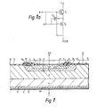
- the device shown in Figure 1 also comprises a first insulated gate field effect transistor T2 which is merged with the bipolar transistor T1 to form a device having the equivalent circuit shown in Figure 1 so that the first insulated gate field effect transistor T2 provides a gateable connection to the emitter region 1 of the bipolar transistor T1.
- the first insulated gate field effect transistor T2 is formed by a further region 6 of the other conductivity type (p+ conductivity type in this example) provided in the emitter region 1, an insulated gate 7 overlying a channel area 8 in the further region 6 and a source region 9 of the one conductivity type (in this example n+ conductivity type) provided in the further region 6.
- the first insulated gate field effect transistor T2 is merged with the bipolar transistor T1 to provide a gateable connection to the emitter region 1 enabling current flow through the emitter region 1 to be controlled by a gate signal supplied to the insulated gate 7 so that when the bipolar transistor T1 is turned off by a negative base signal applied to the base contact 12, the emitter region 1 can be open-circuited by applying a negative signal to the insulated gate 7 to turn off the transistor T2, so forcing current to flow out through the collector-base circuit.
- the gate and base signals may, of course, be derived from the same voltage source (not shown).
- the second insulated gate field effect transistor T3 is of opposite polarity to the first insulated gate field effect transistor T2 so that, as shown in Figure 1 and 1a, the same gate signal can be used to switch on transistor T2 and switch off the transistor T3 (or vice versa).
- the arrangement shown in Figure 1 may be symmetrical about an axis shown by the dotted line 16 in Figure 1 so as to provide a hollow emitter structure with the emitter, further and source regions 1, 6 and 9 then being in the form of annuli, for example rectangular or circular annuli.
- FIGS 2 and 2a illustrate a further embodiment of the invention in which the device shown in Figure 1 has been modified to include a third insulated gate field effect transistor T4 of complementary type to the second insulated gate field effect transistor T3.
- the third insulated gate field effect transistor T4 is provided to form a base drive for the bipolar transistor.
- the two complementary insulated gate field effect transistors T3 and T4 have a common gate connection so as to form a push-pull input stage for the base region 2 of the bipolar transistor T1.
- the application of a positive gate signal to the insulated gates 15 and 18 renders transistor T4 conducting to supply a base drive signal to the bipolar transistor T1 while the application of a negative gate signal renders transistor T3 conducting to enable base charge extraction from the bipolar transistor T1.
- a highly doped p+ type conductivity further region 6 may be formed in the emitter region 1 in a similar manner to the formation of the base region 2 in the collector region 3 using boron ion implantation and/or diffusion while a highly doped n+ type conductivity source region 9 may be formed in the further region 6 in a manner similar the formation of the emitter region 1 in the base region 2 using arsenic (or phosphorous) ion implantation and/or diffusion, in each case using appropriate masks.
- the source region 19a when provided, may be formed using an appropriate mask in the same diffusion and/or ion implantation step as the emitter region 1 while the source region 19b (and drain region 22b in the Figure 3 embodiment), when provided, may be formed using an appropriate mask in the same step as the source region 9, so that no diffusion and/or ion implantation steps additional to those used to produce the Figure 1 embodiment are required for the Figure 2 and 3 embodiments, but merely a different mask arrangement.
- the bipolar transistor T1 described above may form part of a large bipolar device, for example a thyristor structure.
- the n+ substrate 4 may be replaced by a p conductivity type substrate to form a pnpn structure so that the bipolar device may be a thyristor, for example a gate turn-off thyristor GTO or a four layer diode, if the base connection is omitted.
- the insulated gate field effects transistors shown in Figures 1, 2 and 3 have their respective insulated gates formed on the surface 10 ⁇ , at least some of these field effect transistors may have insulated gates formed on side walls of grooves in the surface 10 ⁇ .
Landscapes
- Metal-Oxide And Bipolar Metal-Oxide Semiconductor Integrated Circuits (AREA)
- Bipolar Transistors (AREA)
- Insulated Gate Type Field-Effect Transistor (AREA)
Applications Claiming Priority (2)
| Application Number | Priority Date | Filing Date | Title |
|---|---|---|---|
| GB08612010A GB2190539A (en) | 1986-05-16 | 1986-05-16 | Semiconductor devices |
| GB8612010 | 1986-05-16 |
Publications (3)
| Publication Number | Publication Date |
|---|---|
| EP0247660A2 true EP0247660A2 (de) | 1987-12-02 |
| EP0247660A3 EP0247660A3 (en) | 1990-04-11 |
| EP0247660B1 EP0247660B1 (de) | 1993-04-21 |
Family
ID=10597998
Family Applications (1)
| Application Number | Title | Priority Date | Filing Date |
|---|---|---|---|
| EP87200846A Expired - Lifetime EP0247660B1 (de) | 1986-05-16 | 1987-05-11 | Halbleiteranordnung mit einem Bipolartransistor und Feldeffekttransistoren |
Country Status (5)
| Country | Link |
|---|---|
| US (1) | US4881119A (de) |
| EP (1) | EP0247660B1 (de) |
| JP (1) | JP2635044B2 (de) |
| DE (1) | DE3785483T2 (de) |
| GB (1) | GB2190539A (de) |
Cited By (3)
| Publication number | Priority date | Publication date | Assignee | Title |
|---|---|---|---|---|
| EP0322041A3 (de) * | 1987-12-22 | 1993-04-21 | STMicroelectronics S.r.l. | Integrierter bipolarer Hochspannungsleistungstransistor und Niederspannungs-MOS-Transistorstruktur in Emitterumschaltkonfiguration und Herstellungsverfahren |
| DE4318205A1 (de) * | 1992-06-01 | 1993-12-02 | Fuji Electric Co Ltd | Halbleitervorrichtung |
| EP0646965A1 (de) * | 1993-09-17 | 1995-04-05 | Consorzio per la Ricerca sulla Microelettronica nel Mezzogiorno - CoRiMMe | Eine integrierte Vorrichtung mit einem bipolaren Transistor und einem MOSFET Transistor in Emittorschaltungsanordnung |
Families Citing this family (12)
| Publication number | Priority date | Publication date | Assignee | Title |
|---|---|---|---|---|
| USRE35642E (en) * | 1987-12-22 | 1997-10-28 | Sgs-Thomson Microelectronics, S.R.L. | Integrated high-voltage bipolar power transistor and low voltage MOS power transistor structure in the emitter switching configuration and relative manufacturing process |
| JPH0254537A (ja) * | 1988-08-18 | 1990-02-23 | Seiko Epson Corp | 半導体装置及び半導体装置の製造方法 |
| US4975764A (en) * | 1989-06-22 | 1990-12-04 | David Sarnoff Research Center, Inc. | High density BiCMOS circuits and methods of making same |
| WO1991003078A1 (en) * | 1989-08-17 | 1991-03-07 | Ixys Corporation | Insulated gate thyristor with gate turn on and turn off |
| US5381025A (en) * | 1989-08-17 | 1995-01-10 | Ixys Corporation | Insulated gate thyristor with gate turn on and turn off |
| US5559044A (en) * | 1992-09-21 | 1996-09-24 | Siliconix Incorporated | BiCDMOS process technology |
| US6004840A (en) * | 1994-04-15 | 1999-12-21 | Kabushiki Kaisha Toshiba | Method of fabricating a semiconductor device comprising a MOS portion and a bipolar portion |
| DE69528683T2 (de) * | 1994-04-15 | 2003-06-12 | Kabushiki Kaisha Toshiba, Kawasaki | Halbleiterbauteil und Verfahren zur Herstellung desselben |
| GB2289371B (en) * | 1994-05-05 | 1997-11-19 | Fuji Electric Co Ltd | A semiconductor device and control method |
| US5591655A (en) * | 1995-02-28 | 1997-01-07 | Sgs-Thomson Microelectronics, Inc. | Process for manufacturing a vertical switched-emitter structure with improved lateral isolation |
| US6657240B1 (en) * | 2002-01-28 | 2003-12-02 | Taiwan Semiconductoring Manufacturing Company | Gate-controlled, negative resistance diode device using band-to-band tunneling |
| TW200837947A (en) * | 2007-03-13 | 2008-09-16 | Nat Univ Tsing Hua | The structure and layout of high - efficiency lateral bipolar transistor |
Family Cites Families (12)
| Publication number | Priority date | Publication date | Assignee | Title |
|---|---|---|---|---|
| DE2945324A1 (de) * | 1979-11-09 | 1981-05-21 | Siemens AG, 1000 Berlin und 8000 München | Thyristor mit verbessertem schaltverhalten |
| US4441117A (en) * | 1981-07-27 | 1984-04-03 | Intersil, Inc. | Monolithically merged field effect transistor and bipolar junction transistor |
| IE56341B1 (en) * | 1981-12-16 | 1991-07-03 | Gen Electric | Multicellular thyristor |
| US5014102A (en) * | 1982-04-01 | 1991-05-07 | General Electric Company | MOSFET-gated bipolar transistors and thyristors with both turn-on and turn-off capability having single-polarity gate input signal |
| JPS5927569A (ja) * | 1982-08-06 | 1984-02-14 | Hitachi Ltd | 半導体スイツチ素子 |
| US4623910A (en) * | 1982-09-24 | 1986-11-18 | Risberg Robert L | Semiconductor device |
| EP0106147A1 (de) * | 1982-10-04 | 1984-04-25 | General Electric Company | Abschaltbarer Thyristor |
| CA1200322A (en) * | 1982-12-13 | 1986-02-04 | General Electric Company | Bidirectional insulated-gate rectifier structures and method of operation |
| US4618872A (en) * | 1983-12-05 | 1986-10-21 | General Electric Company | Integrated power switching semiconductor devices including IGT and MOSFET structures |
| US4639761A (en) * | 1983-12-16 | 1987-01-27 | North American Philips Corporation | Combined bipolar-field effect transistor resurf devices |
| US4672407A (en) * | 1984-05-30 | 1987-06-09 | Kabushiki Kaisha Toshiba | Conductivity modulated MOSFET |
| GB2164790A (en) * | 1984-09-19 | 1986-03-26 | Philips Electronic Associated | Merged bipolar and field effect transistors |
-
1986
- 1986-05-16 GB GB08612010A patent/GB2190539A/en not_active Withdrawn
-
1987
- 1987-05-11 EP EP87200846A patent/EP0247660B1/de not_active Expired - Lifetime
- 1987-05-11 DE DE87200846T patent/DE3785483T2/de not_active Expired - Fee Related
- 1987-05-13 JP JP62114893A patent/JP2635044B2/ja not_active Expired - Lifetime
-
1989
- 1989-02-02 US US07/306,243 patent/US4881119A/en not_active Expired - Fee Related
Cited By (5)
| Publication number | Priority date | Publication date | Assignee | Title |
|---|---|---|---|---|
| EP0322041A3 (de) * | 1987-12-22 | 1993-04-21 | STMicroelectronics S.r.l. | Integrierter bipolarer Hochspannungsleistungstransistor und Niederspannungs-MOS-Transistorstruktur in Emitterumschaltkonfiguration und Herstellungsverfahren |
| DE4318205A1 (de) * | 1992-06-01 | 1993-12-02 | Fuji Electric Co Ltd | Halbleitervorrichtung |
| DE4318205C2 (de) * | 1992-06-01 | 1998-04-23 | Fuji Electric Co Ltd | Halbleitervorrichtungen |
| EP0646965A1 (de) * | 1993-09-17 | 1995-04-05 | Consorzio per la Ricerca sulla Microelettronica nel Mezzogiorno - CoRiMMe | Eine integrierte Vorrichtung mit einem bipolaren Transistor und einem MOSFET Transistor in Emittorschaltungsanordnung |
| US5665994A (en) * | 1993-09-17 | 1997-09-09 | Co.Ri.M.Me. Consorzio Per La Ricerca Sulla Microelettronica Nel Mezzogiorno | Integrated device with a bipolar transistor and a MOSFET transistor in an emitter switching configuration |
Also Published As
| Publication number | Publication date |
|---|---|
| DE3785483D1 (de) | 1993-05-27 |
| DE3785483T2 (de) | 1993-10-28 |
| US4881119A (en) | 1989-11-14 |
| JPS62274653A (ja) | 1987-11-28 |
| JP2635044B2 (ja) | 1997-07-30 |
| EP0247660A3 (en) | 1990-04-11 |
| GB2190539A (en) | 1987-11-18 |
| EP0247660B1 (de) | 1993-04-21 |
| GB8612010D0 (en) | 1986-06-25 |
Similar Documents
| Publication | Publication Date | Title |
|---|---|---|
| US6051850A (en) | Insulated gate bipolar junction transistors having built-in freewheeling diodes therein | |
| US6303410B1 (en) | Methods of forming power semiconductor devices having T-shaped gate electrodes | |
| EP0083815B1 (de) | Lateraler Sperrschicht-Feldeffekttransistor | |
| US4969028A (en) | Gate enhanced rectifier | |
| EP0247660B1 (de) | Halbleiteranordnung mit einem Bipolartransistor und Feldeffekttransistoren | |
| EP0697739B1 (de) | Bipolartransistor mit isolierter Steuerelektrode | |
| JP2574267B2 (ja) | 絶縁ゲートトランジスタアレイ | |
| US5200632A (en) | Conductivity modulation mosfet | |
| JPH08222728A (ja) | 絶縁ゲート型半導体装置 | |
| JPH0347593B2 (de) | ||
| US5430323A (en) | Injection control-type Schottky barrier rectifier | |
| US5270230A (en) | Method for making a conductivity modulation MOSFET | |
| US5793066A (en) | Base resistance controlled thyristor structure with high-density layout for increased current capacity | |
| EP0338312B1 (de) | Bipolarer Transistor mit isolierter Steuerelektrode | |
| US5240865A (en) | Method of forming a thyristor on an SOI substrate | |
| US5378903A (en) | Semiconductor device with low on-voltage and large controllable turn-off current | |
| EP0823125A2 (de) | Selbstausrichtendes verfahren für isolierung durch pn-übergang und wannenstruktur | |
| US5728593A (en) | Power insulated-gate transistor having three terminals and a manufacturing method thereof | |
| US5264378A (en) | Method for making a conductivity modulation MOSFET | |
| US5981983A (en) | High voltage semiconductor device | |
| US6111278A (en) | Power semiconductor devices having discontinuous emitter regions therein for inhibiting parasitic thyristor latch-up | |
| JPH07169868A (ja) | 少なくとも1個のバイポーラ・パワーデバイスを有する回路パターン及びその作動方法 | |
| JPH03194974A (ja) | Mos型半導体装置 | |
| US5925900A (en) | Emitter-switched thyristor having a floating ohmic contact | |
| GB2289371A (en) | A semiconductor device and control method |
Legal Events
| Date | Code | Title | Description |
|---|---|---|---|
| PUAI | Public reference made under article 153(3) epc to a published international application that has entered the european phase |
Free format text: ORIGINAL CODE: 0009012 |
|
| AK | Designated contracting states |
Kind code of ref document: A2 Designated state(s): DE FR GB IT NL |
|
| RAP3 | Party data changed (applicant data changed or rights of an application transferred) |
Owner name: N.V. PHILIPS' GLOEILAMPENFABRIEKEN Owner name: PHILIPS ELECTRONIC AND ASSOCIATED INDUSTRIES LIMIT |
|
| PUAL | Search report despatched |
Free format text: ORIGINAL CODE: 0009013 |
|
| AK | Designated contracting states |
Kind code of ref document: A3 Designated state(s): DE FR GB IT NL |
|
| 17P | Request for examination filed |
Effective date: 19901009 |
|
| RAP3 | Party data changed (applicant data changed or rights of an application transferred) |
Owner name: N.V. PHILIPS' GLOEILAMPENFABRIEKEN Owner name: PHILIPS ELECTRONICS UK LIMITED |
|
| 17Q | First examination report despatched |
Effective date: 19920707 |
|
| GRAA | (expected) grant |
Free format text: ORIGINAL CODE: 0009210 |
|
| AK | Designated contracting states |
Kind code of ref document: B1 Designated state(s): DE FR GB IT NL |
|
| PG25 | Lapsed in a contracting state [announced via postgrant information from national office to epo] |
Ref country code: NL Effective date: 19930421 |
|
| REF | Corresponds to: |
Ref document number: 3785483 Country of ref document: DE Date of ref document: 19930527 |
|
| ITF | It: translation for a ep patent filed | ||
| ET | Fr: translation filed | ||
| NLV1 | Nl: lapsed or annulled due to failure to fulfill the requirements of art. 29p and 29m of the patents act | ||
| PLBE | No opposition filed within time limit |
Free format text: ORIGINAL CODE: 0009261 |
|
| STAA | Information on the status of an ep patent application or granted ep patent |
Free format text: STATUS: NO OPPOSITION FILED WITHIN TIME LIMIT |
|
| 26N | No opposition filed | ||
| ITTA | It: last paid annual fee | ||
| ITPR | It: changes in ownership of a european patent |
Owner name: CAMBIO RAGIONE SOCIALE;PHILIPS ELECTRONICS N.V. |
|
| REG | Reference to a national code |
Ref country code: FR Ref legal event code: CD |
|
| PGFP | Annual fee paid to national office [announced via postgrant information from national office to epo] |
Ref country code: DE Payment date: 19970725 Year of fee payment: 11 |
|
| PGFP | Annual fee paid to national office [announced via postgrant information from national office to epo] |
Ref country code: GB Payment date: 19980501 Year of fee payment: 12 |
|
| PGFP | Annual fee paid to national office [announced via postgrant information from national office to epo] |
Ref country code: FR Payment date: 19980519 Year of fee payment: 12 |
|
| REG | Reference to a national code |
Ref country code: FR Ref legal event code: CD |
|
| PG25 | Lapsed in a contracting state [announced via postgrant information from national office to epo] |
Ref country code: DE Free format text: LAPSE BECAUSE OF NON-PAYMENT OF DUE FEES Effective date: 19990302 |
|
| PG25 | Lapsed in a contracting state [announced via postgrant information from national office to epo] |
Ref country code: GB Free format text: LAPSE BECAUSE OF NON-PAYMENT OF DUE FEES Effective date: 19990511 |
|
| GBPC | Gb: european patent ceased through non-payment of renewal fee |
Effective date: 19990511 |
|
| PG25 | Lapsed in a contracting state [announced via postgrant information from national office to epo] |
Ref country code: FR Free format text: LAPSE BECAUSE OF NON-PAYMENT OF DUE FEES Effective date: 20000131 |
|
| REG | Reference to a national code |
Ref country code: FR Ref legal event code: ST |
|
| PG25 | Lapsed in a contracting state [announced via postgrant information from national office to epo] |
Ref country code: IT Free format text: LAPSE BECAUSE OF NON-PAYMENT OF DUE FEES;WARNING: LAPSES OF ITALIAN PATENTS WITH EFFECTIVE DATE BEFORE 2007 MAY HAVE OCCURRED AT ANY TIME BEFORE 2007. THE CORRECT EFFECTIVE DATE MAY BE DIFFERENT FROM THE ONE RECORDED. Effective date: 20050511 |