EP0247543A1 - Druckanschluss für einen Flüssigkeitsdruckwandler - Google Patents
Druckanschluss für einen Flüssigkeitsdruckwandler Download PDFInfo
- Publication number
- EP0247543A1 EP0247543A1 EP87107509A EP87107509A EP0247543A1 EP 0247543 A1 EP0247543 A1 EP 0247543A1 EP 87107509 A EP87107509 A EP 87107509A EP 87107509 A EP87107509 A EP 87107509A EP 0247543 A1 EP0247543 A1 EP 0247543A1
- Authority
- EP
- European Patent Office
- Prior art keywords
- dome
- diaphragm
- liquid
- pressure transducer
- liquid pressure
- Prior art date
- Legal status (The legal status is an assumption and is not a legal conclusion. Google has not performed a legal analysis and makes no representation as to the accuracy of the status listed.)
- Withdrawn
Links
- 239000007788 liquid Substances 0.000 title claims abstract description 62
- 239000007789 gas Substances 0.000 claims abstract description 12
- 239000011148 porous material Substances 0.000 claims description 11
- -1 polyethylene Polymers 0.000 claims description 9
- 230000002209 hydrophobic effect Effects 0.000 claims description 4
- 239000000463 material Substances 0.000 claims description 4
- 229920001343 polytetrafluoroethylene Polymers 0.000 claims description 4
- 239000004810 polytetrafluoroethylene Substances 0.000 claims description 4
- 239000002033 PVDF binder Substances 0.000 claims description 3
- 239000004698 Polyethylene Substances 0.000 claims description 3
- 239000004743 Polypropylene Substances 0.000 claims description 3
- 229920001577 copolymer Polymers 0.000 claims description 3
- 229920000573 polyethylene Polymers 0.000 claims description 3
- 229920002981 polyvinylidene fluoride Polymers 0.000 claims description 3
- 238000007599 discharging Methods 0.000 claims description 2
- 229920001155 polypropylene Polymers 0.000 claims description 2
- 239000004033 plastic Substances 0.000 claims 1
- 229920003023 plastic Polymers 0.000 claims 1
- 210000000188 diaphragm Anatomy 0.000 abstract description 39
- 230000037452 priming Effects 0.000 description 10
- 230000036772 blood pressure Effects 0.000 description 6
- 230000000717 retained effect Effects 0.000 description 5
- 230000008878 coupling Effects 0.000 description 4
- 238000010168 coupling process Methods 0.000 description 4
- 238000005859 coupling reaction Methods 0.000 description 4
- 230000005540 biological transmission Effects 0.000 description 3
- 239000012530 fluid Substances 0.000 description 3
- 230000004927 fusion Effects 0.000 description 3
- 239000012528 membrane Substances 0.000 description 3
- 238000000034 method Methods 0.000 description 3
- 229940058401 polytetrafluoroethylene Drugs 0.000 description 3
- 208000036366 Sensation of pressure Diseases 0.000 description 2
- 238000012986 modification Methods 0.000 description 2
- 230000004048 modification Effects 0.000 description 2
- 239000008280 blood Substances 0.000 description 1
- 210000004369 blood Anatomy 0.000 description 1
- 210000004204 blood vessel Anatomy 0.000 description 1
- 238000010276 construction Methods 0.000 description 1
- 230000005484 gravity Effects 0.000 description 1
- 238000003780 insertion Methods 0.000 description 1
- 230000037431 insertion Effects 0.000 description 1
- 238000005259 measurement Methods 0.000 description 1
- QSHDDOUJBYECFT-UHFFFAOYSA-N mercury Chemical compound [Hg] QSHDDOUJBYECFT-UHFFFAOYSA-N 0.000 description 1
- 229910052753 mercury Inorganic materials 0.000 description 1
- 238000012856 packing Methods 0.000 description 1
- 239000002504 physiological saline solution Substances 0.000 description 1
- 238000002459 porosimetry Methods 0.000 description 1
- 230000003068 static effect Effects 0.000 description 1
Images

Classifications
-
- A—HUMAN NECESSITIES
- A61—MEDICAL OR VETERINARY SCIENCE; HYGIENE
- A61B—DIAGNOSIS; SURGERY; IDENTIFICATION
- A61B5/00—Measuring for diagnostic purposes; Identification of persons
- A61B5/02—Detecting, measuring or recording for evaluating the cardiovascular system, e.g. pulse, heart rate, blood pressure or blood flow
- A61B5/021—Measuring pressure in heart or blood vessels
- A61B5/0215—Measuring pressure in heart or blood vessels by means inserted into the body
-
- G—PHYSICS
- G01—MEASURING; TESTING
- G01L—MEASURING FORCE, STRESS, TORQUE, WORK, MECHANICAL POWER, MECHANICAL EFFICIENCY, OR FLUID PRESSURE
- G01L19/00—Details of, or accessories for, apparatus for measuring steady or quasi-steady pressure of a fluent medium insofar as such details or accessories are not special to particular types of pressure gauges
- G01L19/0007—Fluidic connecting means
- G01L19/0046—Fluidic connecting means using isolation membranes
Definitions
- This invention relates to a liquid pressure transducer dome which transmits the pressure of a liquid, particularly blood, to a liquid pressure transducer.
- a pressure transducer is applied to the patient, in order to measure blood pressure.
- a catheter is held in the patient's blood vessel.
- the proximal end of the catheter is connected to a pressure transducer through a pressure transmission tube and pressure transducer dome (pressure dome).
- the pressure transmission tube and pressure dome are filled with a liquid such as physiological saline solution.
- the blood pressure is transmitted through the liquid held in the tube, and the pressure dome to the pressure transducer through a diaphragm disposed over the bottom plane of the dome.
- the pressure transducer converts the received blood pressure into an electric signal.
- the conventional priming process is to introduce a liquid at an inlet provided at the top of the pressure dome and expel air by the liquid through an air outlet formed at the other position of the dome.
- air bubbles settle on the walls of the pressure dome and diaphragm surface.
- USP 4,462,409 discloses a dome body which is not shaped like a semispherical form but partially assumes a convex-tapered form for the object of facilitating the release of retained air. Yet this dome still fails to give full satisfaction.
- Japanese Patent Disclosure 56-97435 proposes a structure which is designed in a way to give rise to the vertical flow of a liquid in the dome, thereby easily pushing upward air bubbles attached to dome walls to the top portion thereof.
- this proposed device has a undesirable structural complexities.
- a liquid pressure transducer dome has a dome body provided with means for effecting its connection to a liquid pressure transducer, a diaphragm provided in the dome body, and fluid-passage means which allows the introduction of the fluid up to the diaphragm.
- the diaphragm is prepared from a porous film which is pervious to gas but impervious to liquids.
- the central portion of the diaphragm should preferively be rendered transparent or translucent.
- the diaphragm is prepared from hydrophobic materials such as polyethylene, polypropylene, polytetrafluoroethylene, polyvinylidene fluoride or tetrafluoroethylene-hexafluoropropylene copolymer.
- the diaphragm is preferred to have an average pore diameter ranging between 0.01 to 5 ⁇ m.
- the liquid pressure transducer dome embodying this invention need not be constructed in the undermentioned dome-like (namely, the so-called semispherical) form; it may be constituted in any other form, provided it attains the intended object.
- the conventional liquid pressure transducer dome makes use of a diaphragm impervious to both fluids and gas, and consequently the pressure dome has to be provided with a liquid inlet and gas outlet, and found that the application of a porous diaphragm pervious to gas (air), but impervious to a liquid can provide a liquid pressure transducer dome which facilitates the withdrawal of air and is of simple structure.
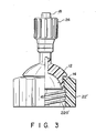
- pressure transducer dome 10 of the present invention has a semispherical body 12.
- the bottom of dome 10 is fitted with circular diaphragm 16 which closes opening 14 at the bottom wall of dome 10.
- Diaphragm 16 is prepared from hydrophobic, porous material which is pervious to gas, but impervious to liquids.
- the diaphragm membrane can be prepared from hydrophobic material such as polyethylene, polypropylene, polytetrafluoroethylene, polyvinylidene fluoride, and tetrafluoroethylene-hexafluoropropylene copolymer. Of the above materials polytetrafluoroethylene is the most preferred.
- the diameter of the pores of diaphragm 16 should preferably fall within the range of 0.01 and 5 ⁇ m on average, more preferably between 0.05 and 2 ⁇ m, and most preferably between 0.08 and 0.5 ⁇ m. From the point of view of mechanical strength, the pore diameter should preferably be about 0.1 ⁇ m on average.
- the pore diameter is determined by the step of optionally selecting about 500 pores by means of, for example, an electronic microscope, and defining the average value as the average pore diameter. If the pores are elliptic, the sum of the lengthwise and crosswise diameters are divided by 2 and the elliptic pores are regarded as circles having a diameter represented by the quotient. The average pore diameter may also be determined by mercury porosimetry.
- the desired porosity of diaphragm 16 is to be 30% or more, preferably 50% or more, and most preferably 60% or more.
- the porosity is determined by the following steps.
- the diaphragm is cut up in a predetermined size (represented by A).
- the weight of a void-free cut piece of the membrane bearing the above-mentioned size is calculated from the specific gravity of the membrane and its volume (B) by the undermentioned formula:
- Diaphragm 16 may be fitted to dome body 12 by means of forced insertion, ultrasonic fusion or caulking which involves the application of an O ring or flat rubber packing.
- the simplest means for the attachment of diaphragm 16 is by thermal fusion.
- dome 12 The center of the head portion of dome 12 is provided with liquid inlet pipe 18 which constitutes liquid passage 20 allowing for the introduction of a liquid into interior 14 of dome 12.
- Liquid-conducting tube 26 coupled to a catheter is connected to pipe 18. Tube 26 is fixed in position by means of threaded engagement member 24.
- Coupling member 22 bearing threaded portion 22a engageable with a pressure transducer is integrally provided in the interior of the lower end of dome 12.
- a priming liquid is taken into dome 12 through tube 26 and passage 20.
- the liquid pressure transducer dome embodying the present invention is characterized, in that when the priming liquid runs from tube 26 into dome 12 through passage 20, the priming liquid runs unidirectionally from passage 20 to the diaphragm, thus suppressing the occurrence of turbulent flows of the priming liquid and the consequent generation of air bubbles.
- the further merit of the present invention is that even if air bubbles arise in dome 12 because of the rapid flow of the priming liquid, air bubbles can be very easily drawn to the outside through porous diaphragm 16.
- central region 16a which constitutes the greater part of diaphragm 16 is rendered transparent by thermal a ultrasonic fusion, and only circumferential region 16b is rendered gas-permeable, then it will be possible to attain not only the discharging of air but also to determine the presence of air bubbles. Particularly, because air bubbles tend to be retained in the junction between diaphragm 16 and dome 12, the above-mentioned process will be sufficient to attain the object of the present invention. However, if the type of transducer and flexibility of the diaphragm are properly selected, it may be possible to accurately measure the liquid pressure even when air is present between diaphragm 16 and the transducer. In such a case, it is not necessary to render diaphragm 16 transparent as above.
- the invention is not limited thereto; it is applicable to any other type of liquid pressure transducer dome.
- the present invention is applicable to any other type of liquid pressure transducer dome where liquid is made to flow, under pressure, against a diaphragm set at the bottom of a dome where the liquid is received, and the liquid pressure is converted to an electric signal by way of a liquid pressure transducer.
- the pressure transducer dome representing the present invention has a porous diaphragm which is pervious to gas but impervious to liquids.
- gases retained in the dome can be drawn to the outside through the diaphragm, therefore allowing for easy priming.
- the dome of the invention dispenses with the need for a gas outlet port in the dome, and consequently ensures the simplification of the construction of a liquid pressure transducer dome.
Landscapes
- Health & Medical Sciences (AREA)
- Life Sciences & Earth Sciences (AREA)
- Physics & Mathematics (AREA)
- Cardiology (AREA)
- Biomedical Technology (AREA)
- Molecular Biology (AREA)
- Vascular Medicine (AREA)
- Biophysics (AREA)
- Pathology (AREA)
- Engineering & Computer Science (AREA)
- General Physics & Mathematics (AREA)
- Heart & Thoracic Surgery (AREA)
- Medical Informatics (AREA)
- Physiology (AREA)
- Surgery (AREA)
- Animal Behavior & Ethology (AREA)
- General Health & Medical Sciences (AREA)
- Public Health (AREA)
- Veterinary Medicine (AREA)
- Measuring Fluid Pressure (AREA)
- Measuring Pulse, Heart Rate, Blood Pressure Or Blood Flow (AREA)
Applications Claiming Priority (2)
| Application Number | Priority Date | Filing Date | Title |
|---|---|---|---|
| JP61120915A JPS62277938A (ja) | 1986-05-26 | 1986-05-26 | 液体圧力トランスデユ−サ−用ド−ム |
| JP120915/86 | 1986-05-26 |
Publications (1)
| Publication Number | Publication Date |
|---|---|
| EP0247543A1 true EP0247543A1 (de) | 1987-12-02 |
Family
ID=14798140
Family Applications (1)
| Application Number | Title | Priority Date | Filing Date |
|---|---|---|---|
| EP87107509A Withdrawn EP0247543A1 (de) | 1986-05-26 | 1987-05-22 | Druckanschluss für einen Flüssigkeitsdruckwandler |
Country Status (2)
| Country | Link |
|---|---|
| EP (1) | EP0247543A1 (de) |
| JP (1) | JPS62277938A (de) |
Cited By (4)
| Publication number | Priority date | Publication date | Assignee | Title |
|---|---|---|---|---|
| EP0326616A4 (de) * | 1986-09-29 | 1989-06-14 | Terumo Corp | Messkammer für flüssigkeitsdruckwandler. |
| FR2728342A1 (fr) * | 1994-12-19 | 1996-06-21 | Inst Francais Du Petrole | Prise de pression selective pour un capteur de pression |
| US5752918A (en) | 1993-06-30 | 1998-05-19 | Medex, Inc. | Modular medical pressure transducer |
| US5868678A (en) | 1993-06-30 | 1999-02-09 | Medex, Inc. | Two-part medical pressure transducer with diaphragm stand-offs |
Citations (2)
| Publication number | Priority date | Publication date | Assignee | Title |
|---|---|---|---|---|
| US4072056A (en) * | 1976-06-28 | 1978-02-07 | Varian Associates, Inc. | Fluid containment structure for transducer system |
| US4252126A (en) * | 1979-07-27 | 1981-02-24 | Medex Inc. | Transducer dome |
-
1986
- 1986-05-26 JP JP61120915A patent/JPS62277938A/ja active Pending
-
1987
- 1987-05-22 EP EP87107509A patent/EP0247543A1/de not_active Withdrawn
Patent Citations (2)
| Publication number | Priority date | Publication date | Assignee | Title |
|---|---|---|---|---|
| US4072056A (en) * | 1976-06-28 | 1978-02-07 | Varian Associates, Inc. | Fluid containment structure for transducer system |
| US4252126A (en) * | 1979-07-27 | 1981-02-24 | Medex Inc. | Transducer dome |
Cited By (6)
| Publication number | Priority date | Publication date | Assignee | Title |
|---|---|---|---|---|
| EP0326616A4 (de) * | 1986-09-29 | 1989-06-14 | Terumo Corp | Messkammer für flüssigkeitsdruckwandler. |
| US5752918A (en) | 1993-06-30 | 1998-05-19 | Medex, Inc. | Modular medical pressure transducer |
| US5848971A (en) | 1993-06-30 | 1998-12-15 | Medex, Inc. | Modular medical pressure transducer |
| US5868678A (en) | 1993-06-30 | 1999-02-09 | Medex, Inc. | Two-part medical pressure transducer with diaphragm stand-offs |
| FR2728342A1 (fr) * | 1994-12-19 | 1996-06-21 | Inst Francais Du Petrole | Prise de pression selective pour un capteur de pression |
| US5602340A (en) * | 1994-12-19 | 1997-02-11 | Institut Francais, Du Petrole | Selective pressure tap for a pressure detector |
Also Published As
| Publication number | Publication date |
|---|---|
| JPS62277938A (ja) | 1987-12-02 |
Similar Documents
| Publication | Publication Date | Title |
|---|---|---|
| US5779674A (en) | Fluid gas removal drip chamber | |
| US5184742A (en) | Deadender cap for luer fitting | |
| US6880404B2 (en) | System elements for measuring pressure in extracorporeal circuits | |
| US3646935A (en) | Fluid collection systems | |
| JP5295249B2 (ja) | 体外医療用流体回路部品及び同部品を含む装置 | |
| US4867153A (en) | Medical drain system for removing liquid from ventilating system | |
| US4976707A (en) | Fluid collection, storage and infusion apparatus | |
| US4050451A (en) | Blood collection and separation device | |
| US5073172A (en) | Device for aspirating wound fluids | |
| US5563584A (en) | Liquid level sensing and monitoring system for medical fluid infusion systems | |
| AU607912B2 (en) | Airless artificial kidney assembly | |
| US4307731A (en) | Multiple sampling needle having one-way valve | |
| EP1516585B1 (de) | Nicht-evakuiertes Blutentnahmeröhrchen | |
| US5722955A (en) | Pressure sensing syringe | |
| GB2085732A (en) | Administration set | |
| US4111807A (en) | Mouth filter for use with pipettes | |
| EP0247543A1 (de) | Druckanschluss für einen Flüssigkeitsdruckwandler | |
| US3461868A (en) | Medicament injection device | |
| JPH0157583B2 (de) | ||
| EP0111087B1 (de) | Absaugdränagegerät für medizinische Zwecke | |
| US4573977A (en) | Bladder-type syringe | |
| US4143659A (en) | Stilligout or dropper particularly for infusion apparatus | |
| US4636196A (en) | Method for providing a bubbleless connection between filling tubes for blood or the like and a container used for said connection | |
| US4606365A (en) | Buoyant blood stop valve | |
| JP2599875B2 (ja) | 液体流量を測定する方法および装置 |
Legal Events
| Date | Code | Title | Description |
|---|---|---|---|
| PUAI | Public reference made under article 153(3) epc to a published international application that has entered the european phase |
Free format text: ORIGINAL CODE: 0009012 |
|
| 17P | Request for examination filed |
Effective date: 19870619 |
|
| AK | Designated contracting states |
Kind code of ref document: A1 Designated state(s): BE DE FR GB SE |
|
| 17Q | First examination report despatched |
Effective date: 19910212 |
|
| STAA | Information on the status of an ep patent application or granted ep patent |
Free format text: STATUS: THE APPLICATION IS DEEMED TO BE WITHDRAWN |
|
| 18D | Application deemed to be withdrawn |
Effective date: 19911227 |
|
| RIN1 | Information on inventor provided before grant (corrected) |
Inventor name: MORIUCHI, YOUSUKE |