EP0247350A2 - Method and device for optimizing the balance of a vehicle wheel - Google Patents
Method and device for optimizing the balance of a vehicle wheel Download PDFInfo
- Publication number
- EP0247350A2 EP0247350A2 EP87105685A EP87105685A EP0247350A2 EP 0247350 A2 EP0247350 A2 EP 0247350A2 EP 87105685 A EP87105685 A EP 87105685A EP 87105685 A EP87105685 A EP 87105685A EP 0247350 A2 EP0247350 A2 EP 0247350A2
- Authority
- EP
- European Patent Office
- Prior art keywords
- tire
- wheel
- unbalance
- static
- motor vehicle
- Prior art date
- Legal status (The legal status is an assumption and is not a legal conclusion. Google has not performed a legal analysis and makes no representation as to the accuracy of the status listed.)
- Granted
Links
Images
Classifications
-
- G—PHYSICS
- G01—MEASURING; TESTING
- G01M—TESTING STATIC OR DYNAMIC BALANCE OF MACHINES OR STRUCTURES; TESTING OF STRUCTURES OR APPARATUS, NOT OTHERWISE PROVIDED FOR
- G01M17/00—Testing of vehicles
- G01M17/007—Wheeled or endless-tracked vehicles
- G01M17/02—Tyres
-
- G—PHYSICS
- G01—MEASURING; TESTING
- G01M—TESTING STATIC OR DYNAMIC BALANCE OF MACHINES OR STRUCTURES; TESTING OF STRUCTURES OR APPARATUS, NOT OTHERWISE PROVIDED FOR
- G01M1/00—Testing static or dynamic balance of machines or structures
- G01M1/14—Determining unbalance
- G01M1/16—Determining unbalance by oscillating or rotating the body to be tested
-
- G—PHYSICS
- G01—MEASURING; TESTING
- G01M—TESTING STATIC OR DYNAMIC BALANCE OF MACHINES OR STRUCTURES; TESTING OF STRUCTURES OR APPARATUS, NOT OTHERWISE PROVIDED FOR
- G01M1/00—Testing static or dynamic balance of machines or structures
- G01M1/30—Compensating unbalance
Abstract
Description
Die Erfindung betrifft ein Verfahren nach dem Oberbegriff des Anspruchs 1 und eine Vorrichtung nach dem Oberbegriff des Anspruchs 13.The invention relates to a method according to the preamble of
Bei einem derartigen Verfahren und einer derartigen Vorrichtung, die aus der DE-OS 30 03 127 bekannt sind, werden beim Zusammenbau eines Kraftfahrzeugrades, das aus Scheibenrad und aufgezogenem Reifen besteht, der Reifen und die Felge so gegeneinander verdreht, daß die statischen Unwuchtkräfte von Reifen und Scheibenrad einander entgegengerichtet sind. Zur Ermittlung der statischen Unwuchtkraft für das Scheibenrad einerseits und den Reifen andererseits wird zunächst die statische Unwucht der Felge gemessen und der Reifen dann in beliebiger Winkelstellung auf die Felge aufgezogen. Es erfolgt dann die Unwuchtmessung des montierten Rades, wobei durch vektorielle Subtraktion der Unwuchten des montierten Rades und der Felge die statische Unwucht des Reifens ermittelt wird. Der Reifen wird dann gegenüber der Felge bzw. dem Scheibenrad so verdreht, daß die statische Unwuchtkraft des Scheibenrades der statischen Unwuchtkraft des Reifens entgegengesetzt gerichtet ist. Dieses Zuordnen von Reifen zu Scheibenrad durch Verdrehen wird auch mit "Matchen" bezeichnet.In such a method and such a device, which are known from DE-OS 30 03 127, when assembling a motor vehicle wheel, which consists of a disc wheel and a mounted tire, the tire and the rim are rotated so that the static unbalance forces of tires and the disc wheel are facing each other. To determine the static unbalance force for the disc wheel on the one hand and the tire on the other hand, the static unbalance of the rim is first measured and the tire is then mounted on the rim in any angular position. The unbalance of the mounted wheel is then carried out, the static unbalance of the tire being determined by vectorial subtraction of the unbalance of the mounted wheel and the rim. The tire is then rotated relative to the rim or the disk wheel so that the static unbalance force of the disk wheel is directed in the opposite direction to the static unbalance force of the tire. This assignment of tires to disc wheels by twisting is also referred to as "matching".
Beim bekannten Verfahren ist es erforderlich, zunächst die statische Unwucht des Scheibenrades ohne aufgezogenen Reifen zu ermitteln. Nach diesem Meßlauf ist es erforderlich, den Reifen auf das Scheibenrad aufzuziehen und dann den zweiten Meßlauf durchzuführen. Unberücksichtigt bleiben hierbei die aus den geometrischen Ungleichförmigkeiten des Scheibenrades resultierenden Unwuchten, die sich beispielsweise aus Zentrierfehlern und Formfehlern ergeben können. Beim Verdrehen des Reifens.gegenüber dem Scheibenrad kann es bei Vorhandensein einer geometrischen Ungleichförmigkeit des Scheibenrades geschehen, daß die Laufruhe nicht optimal verbessert und unter Umständen sogar verschlechtert wird.In the known method, it is first necessary to determine the static unbalance of the disc wheel without the tire being mounted. After this measuring run, it is necessary to mount the tire on the disc wheel and then to carry out the second measuring run. The unbalances resulting from the geometric non-uniformities of the disk wheel are not taken into account here, which can result, for example, from centering errors and form errors. When turning the tire . compared to the disk wheel, if there is a geometric non-uniformity of the disk wheel, it can happen that the running smoothness is not optimally improved and possibly even worsened.
Aufgabe der Erfindung ist es demgegenüber, bei einem Verfahren und einer Vorrichtung der eingangs genannten Art unter Berücksichtigung der tatsächlichen Einflüsse auf das Laufverhalten des Rades eine Optimierung der Laufruhe zu erreichen.In contrast, the object of the invention is to achieve smooth running optimization in a method and a device of the type mentioned at the outset, taking into account the actual influences on the running behavior of the wheel.
Diese Aufgabe wird bei der Erfindung verfahrensmäßig durch die kennzeichnenden Merkmale des Anspruchs 1 und vorrichtungsmäßig durch die kennzeichnenden Merkmale des Anspruchs 13 gelöst.In the case of the invention, this object is achieved procedurally by the characterizing features of
Bei der Erfindung werden aus den Meßwerten der beiden Unwuchtmeßläufe und dem Wert des gespeicherten Verdrehwinkels zwischen Reifen und Scheibenrad bei diesen Meßläufen sowohl der Unwuchtvektor des Reifens als auch der durch geometrische Ungleichförmigkeiten des Scheibenrades bedingte Unwüchtvektor für die Berechnung des Matchwinkels verwendet. In "Werkstatt und Betrieb 103" (170, 3, Seiten 183 bis 188) und dem Sonderdruck aus "Werkstatt und Betrieb 105" (1972) Heft 11, Seiten 1 bis 7, ist es bekannt, die geometrischen Ungleichförmigkeiten des Scheibenrades durch Abtasten zu ermitteln. In der,, DE-OS 30 03 127 werden geometrische Un- gleichförmigkeiten des Scheibenrades überhaupt nicht berücksichtigt.In the invention, both the unbalance vector of the tire and the unbalance vector caused by geometric non-uniformity of the disk wheel are used for the calculation of the match angle from the measured values of the two unbalance measurement runs and the value of the stored angle of rotation between the tire and the disk wheel in these measurement runs. In "Werkstatt und Betrieb 103" (170, 3, pages 183 to 188) and the reprint from "Werkstatt und Betrieb 105" (1972)
Unter der Voraussetzung, daß das Scheibenrad keine oder nur vernachlässigbar geringe Massenungleichförmigkeiten aufweist, lassen sich aus den während der beiden Meßläufe gewonnenen Meßwerten die statischen und dynamischen Unwuchtvektoren bzw. 1. Harmonische ermitteln, die auf ungleiche Massenverteilung am Reifen und auf geometrische Ungleichförmigkeiten (Exzentrizitäts- bzw. Zentrierfehler oder Formfehier) des Scheibenrids zurückzuführen sind, ermitteln. Die geometrischen Ungleichförmigkeiten des Scheibenrades äußern sich bei aufmGntier- tem Reifen als Unwuchtkräfte, da der Reifen durch die geometrischen Ungleichförmigkeiten des Scheibenrades aus seiner zentrierten Lage gebracht ist und die hieraus resultierenden Unwuchtkräfte demzufolge auf die geometrischen Ungleichförmigkeiten des Scheibenrades zurückführbar sind.Provided that the disc wheel has no or only negligibly small mass non-uniformities, the static and dynamic unbalance vectors or 1st harmonics can be determined from the measured values obtained during the two measuring runs, which are based on uneven mass distribution on the tire and on geometric non-uniformities (eccentricity or centering error or misalignment) of the disc rider. The geometrical nonuniformities of the disc wheel is manifested in encouraging G ntier- tem tire as imbalance forces as the tire is brought by the geometrical nonuniformities of the disc wheel from its centered position and the resulting imbalance forces accordingly to the geometrical nonuniformities of the disc wheel recyclable are.
Der bei der Erfindung erzielten Optimierung der Laufruhe liegt die überlegung zugrunde, daß die aus den Massenungleichförmigkeiten des Reifens resultierenden Unwuchtkräfte den durch die geometrischen Ungleichförmigkeiten des Scheibenrades bedingten Unwuchtkräften am Kraftfahrzeugrad entgegengerichtet werden. Aus den beiden Meßläufen lassen sich die erforderlichen Unwuchtvektoren bestimmen.The optimization of the smoothness achieved in the invention is based on the consideration that the unbalance forces resulting from the mass non-uniformities of the tire are counteracted by the unbalance forces on the motor vehicle wheel caused by the geometric non-uniformities of the disk wheel. The required unbalance vectors can be determined from the two measurement runs.
Falls das Scheibenrad eine geringere Qualität aufweist und eine ungleiche Massenverteilung besitzt, was zu Unwuchtkräften führt, werden in einem zusätzlichen Meßlauf, wie im Anspruch 2 angegeben, an dem bloßen Scheibenrad,ohne aufgezogenen Reifen, diese Unwuchtkräfte gemessen und eliminiert. Das Eliminieren kann dadurch geschehen, daß entsprechende Unwuchtgewichte an der Felge befestigt werden oder daß die gemessenen Unwuchtkräfte gespeichert und bei der nachfolgenden Auswertung im Sinne der Eliminierung berücksichtigt werden. Dieser Meßlauf mit der bloßen Felge wird bevorzugt vor den beiden Meßläufen durchgeführt, bei welchen der Reifen auf das Scheibenrad aufgezogen ist.If the disc wheel is of lower quality and has an uneven mass distribution, which leads to unbalanced forces, these unbalanced forces are measured and eliminated in an additional measuring run, as stated in
Für eine einwandfreie Optimierung der Laufruhe ist es nämlich erforderlich, daß die aus ungleicher Massenverteilung des Scheibenrades resultierenden Unwuchtkräfte, sei es durch entsprechenden Unwuchtausgleich an der Felge oder durch entsprechende Berücksichtigung bei der Berechnung, eliminiert werden.For a perfect optimization of the smooth running, it is in fact necessary that the unbalance forces resulting from the uneven mass distribution of the disc wheel are eliminated, be it by appropriate unbalance compensation on the rim or by appropriate consideration in the calculation.
Ferner werden für die Ermitttung des beim Matchen zur Anwendung kommenden Verdrehwinkels zwischen Reifen und Scheibenrad die ermittelten statischen und dynamischen Unwuchtvektoren mit Einflußfaktoren multipliziert, die proportional sind zu untereinander verschiedenen Einflüssen, die auf die Laufruhe des Kraftfahrzeugrades einwirken.Furthermore, the determined static and dynamic unbalance vectors are multiplied by influencing factors which are proportional to mutually different influences which affect the smooth running of the motor vehicle wheel in order to determine the twist angle between tire and disc wheel which is used in matching.
Durch die Maßnahme des Anspruchs 3 wird berücksichtigt, daß die statische Unwucht auf die Laufruhe des Kraftfahrzeugrades einen anderen Einfluß ausübt als die dynamische Unwucht. Durch die Maßnahme des Anspruchs 4 wird berücksichtigt, daß die Reifenunwucht einen anderen Einfluß auf die Laufruhe des Kraftfahrzeugrades ausübt als die aus den geometrischen Ungleichförmigkeiten des Scheibenrades resultierende Unwucht.The measure of claim 3 takes into account that the static imbalance exerts a different influence on the smooth running of the motor vehicle wheel than the dynamic imbalance. The measure of
Durch die Maßnahme des Anspruchs 5 wird berücksichtigt, daß die Unwuchtkräfte des am Fahrzeug montierten Kraftfahrzeugrades an der Außenseite des Rades mit einem größeren Hebelarm an der Radaufhängung zur Wirkung kommen als die an der Innenseite liegenden Unwuchtkräfte.The measure of claim 5 takes into account that the unbalance forces of the motor vehicle wheel mounted on the vehicle come into effect on the outside of the wheel with a larger lever arm on the wheel suspension than the unbalance forces lying on the inside.
Durch das in den Ansprüchen 6 bis 8 angegebene Wenden des Reifens um eine zu seiner Laufachse senkrechte Achse ist es möglich, am Reifen wirkende Unwuchten und durch das Scheibenrad veranlaßte Unwuchtkräfte in den beiden Ausgleichsebenen in entgegengesetzte Richtungen beim Matchen gegeneinander zu richten.Due to the turning of the tire specified in claims 6 to 8 about an axis perpendicular to its running axis, it is possible to direct unbalance acting on the tire and the unbalance forces caused by the disc wheel in the two compensation planes in opposite directions against each other when matching.
Bei der durch die Erfindung erzielten Optimierung der Laufruhe des Kraftfahrzeugrades wird die Tatsache ausgenützt, daß in den meisten Fällen die im wesentlichen aus Unwuchten, Radial- und Seitenkraftschwankungen resultierende Laufunruhen die gleichen Ursachen haben. Zur Verbesserung der Laufruhe trägt auch der Umstand bei, daß die noch verbleibenden Unwuchtkräfte relativ niedrig sind und mit geringen Ausgleichsgewichten ausgeglichen werden können. Dies wirkt sich insbesondere bei der Verringerung des Latschmassenunterschieds, der ebenfalls die Laufruhe des Kraftzeugrades beeinflußt, vorteilhaft aus.In the optimization of the smooth running of the motor vehicle wheel achieved by the invention, use is made of the fact that, in most cases, the uneven running resulting essentially from unbalance, radial and lateral force fluctuations have the same causes. Also helps to improve smoothness the fact that the remaining unbalance forces are relatively low and can be compensated with low counterweights. This has an advantageous effect, in particular, in the reduction of the difference in contact mass, which likewise influences the smooth running of the motor vehicle wheel.
Anhand der beiliegenden Figuren wird die Erfindung noch näher erläutert. Es zeigt:
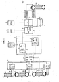
- Fig. 1 ein Blockschaltbild für die Vorrichtung zur Durchführung der Erfindung und
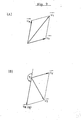
- Fig. 2(A) und 2(B) Vektordiagramme zur Erläuterung der Erfindung.
- Fig. 1 is a block diagram for the device for carrying out the invention and
- 2 (A) and 2 (B) vector diagrams for explaining the invention.
Ein Kraftfahrzeugreifen, der aus einem Scheibenrad 1 und einem darauf aufgezogenen Reifen 2 besteht, wird unter Zuhilfenahme einer in der Fig. 1 dargestellten Schaltungsanordnung durch Matchen, d. h. durch Verdrehen des Reifens 2 gegenüber dem Scheibenrad 1, im Hinblick auf seine Laufruhe optimiert. Die Meßläufe werden an einer nicht näher dargestellten Auswuchtmaschine durchgeführt, wobei das Scheibenrad bzw. das Kraftfahrzeugrad auf eine Wuchtspindel in bekannter Weise aufgespannt ist. Nicht näher dargestellte Meßwertaufnehmer messen während des Meßlaufs Größe und Winkellage von Unwuchten, wobei in einer an die Meßwertaufnehmer angeschlossenen Auswerteelektronik 3 differenziert wird nach Unwuchtkräften Ü für einen Unwuchtvektor in einer rechten Ausgleichsebene und nach für einen Unwuchtvektor in einer linken Ausgleichsebene. Eine Abtasteinrichtung 15 tastet eine Markierung auf dem Scheibenrad 1, beispielsweise das Luftventil oder eine andere feste Einrichtung am Scheibenrad 11 ab und gibt an die Auswerteelektronik 3 ein entsprechendes Winkelbezugssignal, beispielsweise für den Winkel 0.A motor vehicle tire, which consists of a
Es wird zunächst der Verfahrensablauf erläutert, bei welchem die Messungen an Kraftfahrzeugrädern durchgeführt werden, die Scheibenräder mit vernachlässigbar geringen Massenungleichförmigkeiten besitzen. Bei Stahlscheibenrädern kann man in der Regel davon ausgehep, daß diese vernachlässigbar geringe Massenungleichförmigkeiten aufweisen, so daß der in der Fig. 1 dargestellte Meßlauf (1) mit dem bloßen Scheibenrad 1 ohne aufgezogenem Reifen weggelassen werden kann. Es ist natürlich möglich, diesen Meßlauf (1) mit bloßem Scheibenrad immer durchzuführen, um festzustellen, ob am Scheibenrad durch Massenungleichförmigkeiten verursachte Unwuchten, welche durch die nachfolgende Berechnung oder durch an der Felge anzusetzende Ausgleichsgewichte eliminiert werden müssen, vorhanden sind oder nicht.The process sequence is first explained, in which the measurements are carried out on motor vehicle wheels which have disc wheels with negligibly low mass nonuniformities. In the case of steel disc wheels, it can generally be assumed that they have negligible mass nonuniformities, so that the measuring run (1) shown in FIG. 1 with the
Für die Durchführung des Meßlaufs (2) wird der Reifen 2 auf das. Scheibenrad 1 in beliebiger Winkelstellung aufgezogen. In diesem Meßlauf werden die Unwuchten für die linke und rechte Ausgleichsebene gemessen und in der Auswerteelektronik 3 die Unwuchtvektoren
Nach diesem Meßlauf wird der Reifen 2 auf dem Scheibenrad 1 um einen bestimmten Winkel ψ1 verdreht. Dieser Winkel kanh beliebig, bevorzugt jedoch 180°, sein und wird für die Auswertung in einem Vektorrechner 4 gespeichert. Dann wird ein dritter Meßlauf (3) durchgeführt, während welchem in der Auswerteelektronik 3 für die rechte und linke Ausgleichsebene die Unwuchtvektoren
In der Fig. 2 wird anhand der beiden Vektordiagramme (A) und (B) dargestellt, wie sich die Lage der gemessenen Unwuchtvektoren ![]()
![]()
![]()
- Dr die dynamischen Unwuchtvektoren der rechten Ausgleichsebene,
- Dℓ die dynamischen Unwuchtvektoren in der linken Ausgleichsebene und
- S die statischen Unwuchtvektoren.
- D r the dynamic unbalance vectors of the right compensation plane,
- D ℓ the dynamic unbalance vectors in the left compensation plane and
- S the static unbalance vectors.
Die dynamischen Unwuchtvektoren für die jeweils linke und rechte Ausgleichsebene am Reifen und am Scheibenrad sowie die jeweiligen statischen Unwuchtvektoren für Reifen und Scheibenrad werden im Vektorrechner 4 ermittelt.The dynamic unbalance vectors for the respective left and right compensation planes on the tire and on the disk wheel and the respective static unbalance vectors for tire and disk wheel are determined in the
Falls es sich um Scheibenräder handelt, bei denen aufgrund von Massenungleichförmigkeiten so hohe statische und dynamische Unwuchtkräfte an der bloßen Felge auftreten, daß diese berücksichtigt werden müssen, werden diese Unwuchtkräfte, falls sie nicht durch Anbringen entsprechender Ausgleichsgewichte an der Felge eliminiert sind, durch die Berechnung im Vektorrechner 4 eliminiert. In der Auswerteschaltung 3 werden hierzu aus den von den Meßwertaufnehmern abgegebenen Meßwerten für die beiden Ausgleichsebenen die Unwuchtvektoren
In einem an den Vektorrechner 4 angeschlossenen Optimierungsrechner 6 werden die durch das Scheibenrad bedingten und die für den Reifen ermittelten dynamischen und statischen Unwuchtvektoren mit Einflußfaktoren K1, K2, K3 und K4, welche in einem Speicher 5 enthalten sind, multipliziert. Diese Einflußfaktoren können durch beispielsweise eine Tastatur oder eine andere Eingabeeinrichtung in den Speicher 5 eingegeben werden. Der Einflußfaktor K1 gibt den Einfluß der dynamischen Unwuchten, der Einflußfaktor K2 den Einfluß der statischen Unwuchten, der Einflußfaktor K3 den Unterschied der Einflüsse des Scheibenrades und des Reifens und der Einflußfaktor K4 den Unterschied der Einflüsse der Radaußenseite und Radinnenseite bei der Auswirkung auf die Laufruhe des Kraftfahrzeugrades wieder. Bei diesen Einflußfaktoren handelt es sich um empirische Werte. Die Einflußfaktoren hängen vom Kraftfahrzeugtyp und auch von dem Typ des Kraftfahrzeuges ab. Größenordnungsmäßig haben diese Faktoren etwa folgende Werte:![]()
![]()
![]()
![]()
![]()
![]()
![]()
![]()
Im Optimierungsrechner 6 wird einerseits, dargestellt durch eine Einheit 7, der optimale Matchwinkelγo, der zugeordnet ist zu einem beim Matchen erzielbaren minimalen, nach dem Matchen noch verbleibenden ersten Laufunruhewert UVZ1, ermittelt. Ferner wird im Optimierungsrechner 6, dargestellt durch eine Einheit 8, ermittelt, ob beim Wenden des Reifens um eine zu seiner Laufachse senkrechte Achse mit zugeordnetem Matchwinkel γo durch einen erzielbaren zweiten und noch verbleibenden Laufunruhewert UVZ2 eine Verringerung des nach dem Matchen noch verbliebenen ersten Laufunruhewertes UVZ1 erreicht wird. Das Wenden kann dann zu einer weiteren Verringerung dieses nach dem Matchen noch verbliebenen Laufunruhewertes führen, wenn beispielsweise durch den Reifen und das Scheibenrad in beiden Ausgleichsebenen entgegengesetzt gerichtete Unwuchtkräfte hervorgerufen werden.On the one hand, in the optimization computer 6, represented by a unit 7, the optimum match angle γo , which is assigned to a minimum first uneven running value UVZ 1 that can be achieved during matching, is determined. Furthermore, in the optimization computer 6, represented by a unit 8, it is determined whether, when turning the tire about an axis perpendicular to its running axis with an associated match angle γ o , an achievable second and still remaining uneven running value UVZ 2 reduces the first remaining after matching Uneven running value UVZ 1 is reached. The turning can then lead to a further reduction in this uneven running value that remains after the matching, if, for example, the tire and the disk wheel have opposite directions in both compensation planes Unbalance forces are caused.
In einer dem Optimierungsrechner 6 nachgeordneten Vergleichseinrichtung 10 wird gegebenenfalls unter Berücksichtigung eines in einem Speicher 9 abgespeicherten Differenz-Grenzwertes ΔUVZ für die Differenz der beiden Laufunruhewerte UVZ1 und UVZ2 ermittelt, ob der nach dem Matchen noch verbleibende erste Laufunruhewert UVZ1 kleiner ist als der noch verbleibende zweite Laufunruhewert UVZ2 nach dem Wenden, wobei gegebenenfalls dem zweiten Laufunruhewert UVZ2 der im Speicher 9 gespeicherte Differenz-Grenzwert ΔUVZ hinzuaddiert wird. Durch entsprechende Bemessung des Differenz-Grenzwertes ΔUVZ läßt sich ermitteln, ob ein zusätzliches Wenden des Reifens sich lohnt.In a
In einem weiteren Vergleicher 12 kann der Unterschied AUVZ1 zwischen dem Laufunruhewert, der nach der ersten Verdrehung des Reifens 2 gegenüber dem Scheibenrad 1 um den Verdrehwinkel γ1 zwischen den beiden Meßläufen (2) und (3) mit aufgezogenem Reifen erreicht wird, und dem nach dem Matchen bei der zweiten Verdrehung des Reifens gegenüber dem Scheibenrad um den Verdrehwinkel γo erzielbaren ersten Laufunruhewert UVZ1 mit einem weiteren, in einem Speicher 11 abgespeicherten Minimalwert ΔUVZmin verglichen werden. Hierdurch läßt sich feststellen, ob sich die Durchführung des Matchens, d. h. das zweite Verdrehen des Reifens 2 gegenüber dem Scheibenrad 2 um den Matchwinkel γo , lohnt.In a
In Abhängigkeit von den Vergleichsergebnissen wird dann kein Matchen durchgeführt oder allein das Verdrehen des Reifens 2 gegenüber dem Scheibenrad 1 in Abhängigkeit von dem Matchwinkelγo oder noch zusätzlich dazu das Wenden des Reifens 2 auf dem Scheibenrad 1. Dies erfolgt in einem mit (4) in der Fig. 1 bezeichneten Verfahrensschritt.Depending on the comparison results, no matching is then carried out or only the turning of the
Eine weitere Entscheidungseinrichtung 13, welche dem Vergleicher 10 nachgeschaltet ist, kann entscheiden, ob das Wenden des Reifens 2 um eine zu seiner Laufachse senkrechte Achse erlaubt ist oder nicht. In einer Anzeigeeinrichtung 14 kann dann jeweils der entsprechende Matchwinkel, um welchen der Reifen 2 gegenüber dem Scheibenrad 1 verdreht werden muß, angezeigt werden. Das Verdrehen des Reifens 2 gegenüber dem Scheibenrad 1 erfolgt dann bevorzugt ausgehend von der letzten Winkellage, die der Reifen 2 gegenüber dem Scheibenrad 1 im Meßlauf (3) eingenommen hat. Bei der Ermittlung des Matchwinkels γo bzw. bei der zweiten Verdrehung des Reifens gegenüber dem Scheibenrad beim Matchen ist der gespeicherte Winkel mit welchem nach dem Meßlauf (2) der Reifen 2 gegenüber dem Scheibenrad 1 zum ersten Mal verdreht wurde, zu berücksichtigen.A further decision device 13, which is connected downstream of the
Bei der Erfindung wird eine Minimierung der Einflußgrößen, welche die Laufruhe eines Kraftfahrzeugrades stören, erreicht. Es werden die günstigsten Voraussetzungen geschaffen, um durch Matchen und gegebenenfalls durch Wenden des Reifens gegenüber dem Scheibenrad, eine optimale Laufruhe des kompletten Kraftfahrzeugrades zu erzielen. An diesem werden nach dem Matchen gegebenenfalls noch vorhandene Restunwuchten durch entsprechendes Einsetzen von Ausgleichsgewichten beseitigt. In vorteilhafter Weise können weiterhin die hintereinander an den gemessenen Kraftfahrzeugrädern ermittelten statischen und dynamischen Unwuchtvektoren gespeichert werden. Durch Vergleich dieser gespeicherten Daten läßt sich eine weitere Optimierung der Laufruhe erreichen dadurch, daß beim Errechnen sich ergebende günstigere Paarungen von Reifen und Scheibenrad bei den schon gemessenen Kraftfahrzeugreifen sich ergeben. Durch entsprechende Umpaarung können dann die Reifen und Scheibenräder der in Frage kommenden Kraftfahrzeugräder gegeneinander ausgetauscht werden. Hierdurch läßt sich vermeiden, daß beispielsweise bei einem Kraftfahrzeugrad mit guter Felge und schlechtem Reifen oder gutem Reifen und schlechter Felge keine Optimierung der Laufruhe erreicht werden kann. Durch entsprechenden Austausch von Reifen und Felge in Abhängigkeit von dem vorstehend angegebenen Vergleich der erfaßten Unwuchtvektoren für die gemessenen Kraftfahrzeugräder läßt sich die angestrebte Optimierung dann erzielen.The invention minimizes the influencing variables which disturb the smooth running of a motor vehicle wheel. The most favorable conditions are created in order to achieve optimal smooth running of the entire motor vehicle wheel by matching and, if necessary, turning the tire relative to the disc wheel. Any residual imbalances that may still be present on this are eliminated by appropriately using counterweights. Advantageously, the static and dynamic unbalance vectors determined one after the other on the measured motor vehicle wheels can also be stored. By comparing these stored data, a further optimization of the smooth running can be achieved in that the more favorable pairings of tires and disc wheel which result in the calculation result in the already measured motor vehicle tires. The tires and disc wheels of the motor vehicle wheels in question can then be exchanged for one another by appropriate pairing. This allows Avoid that, for example, with a motor vehicle wheel with a good rim and bad tire or a good tire and bad rim, no optimization of the smoothness can be achieved. The desired optimization can then be achieved by a corresponding exchange of tires and rims depending on the comparison of the unbalance vectors detected for the measured motor vehicle wheels.
Auch ist es zusätzlich noch möglich, mit Hilfe von Vergleichseinrichtungen und den verwendeten Grenz- und Minimalwerten sowie mit zulässigen Vergleichszahlen für die verbleibenden Laufunruhewerte, anzuzeigen, ob ungünstige Laufunruhe-Konfigurationen oder Unwuchtkonfigurationen oder nicht weiter verbesserbare Zustände bei gemessenen Kraftfahrzeugrädern vorhanden sind.It is also additionally possible, with the aid of comparison devices and the limit and minimum values used and with permissible comparison numbers for the remaining rough-running values, to indicate whether there are unfavorable rough-running configurations or unbalance configurations or conditions that cannot be further improved in measured motor vehicle wheels.
Claims (14)
Priority Applications (1)
| Application Number | Priority Date | Filing Date | Title |
|---|---|---|---|
| AT87105685T ATE49477T1 (en) | 1986-05-26 | 1987-04-16 | METHOD AND DEVICE FOR OPTIMIZING THE SMOOTH RUNNING OF AN AUTOMOTIVE WHEEL. |
Applications Claiming Priority (2)
| Application Number | Priority Date | Filing Date | Title |
|---|---|---|---|
| DE3617625A DE3617625C1 (en) | 1986-05-26 | 1986-05-26 | Method and device for optimizing the smooth running of a motor vehicle wheel |
| DE3617625 | 1986-05-26 |
Publications (3)
| Publication Number | Publication Date |
|---|---|
| EP0247350A2 true EP0247350A2 (en) | 1987-12-02 |
| EP0247350A3 EP0247350A3 (en) | 1988-04-06 |
| EP0247350B1 EP0247350B1 (en) | 1990-01-10 |
Family
ID=6301639
Family Applications (1)
| Application Number | Title | Priority Date | Filing Date |
|---|---|---|---|
| EP87105685A Expired - Lifetime EP0247350B1 (en) | 1986-05-26 | 1987-04-16 | Method and device for optimizing the balance of a vehicle wheel |
Country Status (6)
| Country | Link |
|---|---|
| US (1) | US4817429A (en) |
| EP (1) | EP0247350B1 (en) |
| JP (1) | JP2544137B2 (en) |
| AT (1) | ATE49477T1 (en) |
| DE (2) | DE3617625C1 (en) |
| ES (1) | ES2013613B3 (en) |
Cited By (2)
| Publication number | Priority date | Publication date | Assignee | Title |
|---|---|---|---|---|
| GR900100677A (en) * | 1989-09-14 | 1992-01-20 | Fmc Corp | Method for detecting the tyres and wheels troubles |
| CN104062072A (en) * | 2014-06-24 | 2014-09-24 | 西安交通大学 | Shafting dynamic balance multi-target optimization method based on differential search algorithm |
Families Citing this family (23)
| Publication number | Priority date | Publication date | Assignee | Title |
|---|---|---|---|---|
| US4776215A (en) * | 1987-04-30 | 1988-10-11 | Dynabal Corporation | Dynamic balancing system and method |
| DE3821239C2 (en) * | 1988-06-23 | 1996-10-24 | Dittel Walter Gmbh | Method for balancing rotating parts and device for carrying out the method |
| US4879792A (en) * | 1988-11-07 | 1989-11-14 | Unitedtechnologies Corporation | Method of balancing rotors |
| US4952154A (en) * | 1989-09-14 | 1990-08-28 | Pruitt Carl W | Demonstrator device for tire eccentricities |
| US5103595A (en) * | 1990-05-14 | 1992-04-14 | Fmc Corporation | Apparatus and method for reducing vibration characteristics in a wheel rim and tire assembly |
| DE4027097A1 (en) * | 1990-08-28 | 1992-03-05 | Hofmann Maschinenbau Gmbh | METHOD AND DEVICE FOR IMPROVING TIRE SEATS IN A MOTOR VEHICLE WHEEL |
| US5237505A (en) * | 1991-05-03 | 1993-08-17 | Illinois Toll Works Inc. | Method and apparatus utilizing static imbalance to reduce vibration caused by tire/wheel assemblies and tire/wheel assembly made using same |
| DE4202803C1 (en) * | 1992-01-31 | 1993-07-15 | Hofmann Werkstatt-Technik Gmbh, 6102 Pfungstadt, De | Method of removing tyres from wheel rims - has arms squeezing beam into wheel well controlled using arm force, arm position and wheel torque sensors |
| JP3133726B2 (en) | 1998-03-06 | 2001-02-13 | 株式会社ブリヂストン | Tire / wheel assembling method, recording medium recording a phase angle calculation program when assembling tire and wheel, tire / wheel assembly |
| DE10064360A1 (en) * | 2000-12-21 | 2002-07-04 | B I G Gentilini Gmbh | Method and device for classifying a rim and a tire and for mounting a wheel |
| EP1371961B1 (en) * | 2001-02-20 | 2006-04-12 | Bridgestone Corporation | Wheel balance adjusting device and wheel balance adjusting method |
| US6606902B2 (en) | 2001-07-09 | 2003-08-19 | The Goodyear Tire & Rubber Company | Method of improving steering performance robustness utilizing stiffness non-uniformity in tire/wheel |
| US6668635B2 (en) | 2001-07-09 | 2003-12-30 | The Goodyear Tire & Rubber Company | Method of improving steering performance robustness utilizing dimensional non-uniformity in tire/wheel |
| US6672148B2 (en) | 2001-07-09 | 2004-01-06 | The Goodyear Tire & Rubber Company | Method of improving steering performance robustness utilizing mass non-uniformity in tire/wheel |
| DE10228164C1 (en) * | 2002-06-24 | 2003-08-14 | Aldo Vanetta | Wheel rim manufacture, removes metal locally for partial correction of imbalance, whilst matching residual imbalance to measured tire imbalance |
| EP1398610B1 (en) | 2002-09-13 | 2005-05-25 | Snap-on Equipment Srl a unico socio. | Method and apparatus for determining geometrical data of a motor vehicle wheel mounted rotatably about an axis of rotation |
| DE10257907B4 (en) * | 2002-12-11 | 2011-09-29 | Snap-On Equipment Gmbh | Method and apparatus for checking the uniformity of a pneumatic tire |
| US7191650B2 (en) * | 2003-02-18 | 2007-03-20 | Hennessy Industries, Inc. | Wheel balancer with continuous static imbalance display |
| DE60301504T2 (en) * | 2003-09-04 | 2006-02-23 | Snap-On Equipment S.R.L A Unico Socio, Correggio | Method for tuning a vehicle wheel |
| IT1349275B1 (en) * | 2003-11-28 | 2008-11-20 | Imt Intermato S P A | METHOD AND SYSTEM FOR THE PRODUCTION OF ALLOY WHEELS FOR MOTOR VEHICLES. |
| US7832288B2 (en) * | 2004-05-12 | 2010-11-16 | Pirelli Tyre S.P.A. | Method for determining a force at the hub of a wheel of a vehicle while traveling and wheel suitable for allowing said method to be carried out |
| DE102018104846B3 (en) * | 2018-03-02 | 2019-08-01 | Schenck Rotec Gmbh | Method for calibrating a balancing machine |
| US10801911B2 (en) * | 2019-03-07 | 2020-10-13 | GM Global Technology Operations LLC | Wheel and tire assembly uniformity |
Citations (1)
| Publication number | Priority date | Publication date | Assignee | Title |
|---|---|---|---|---|
| DE3003127A1 (en) * | 1979-01-30 | 1980-07-31 | Bridgestone Tire Co Ltd | BALANCING AND ASSEMBLY PROCEDURE FOR TIRED WHEELS |
Family Cites Families (2)
| Publication number | Priority date | Publication date | Assignee | Title |
|---|---|---|---|---|
| JPS54131201A (en) * | 1978-04-03 | 1979-10-12 | Maruyama Seiki Kk | Method of assemblying tire and disc wheel |
| US4279287A (en) * | 1979-12-17 | 1981-07-21 | Motor Wheel Corporation | Method of wheel manufacture for correcting rotational non-uniformity of a pneumatic tire and wheel assembly |
-
1986
- 1986-05-26 DE DE3617625A patent/DE3617625C1/en not_active Expired
-
1987
- 1987-04-16 ES ES87105685T patent/ES2013613B3/en not_active Expired - Lifetime
- 1987-04-16 AT AT87105685T patent/ATE49477T1/en not_active IP Right Cessation
- 1987-04-16 DE DE8787105685T patent/DE3761402D1/en not_active Expired - Lifetime
- 1987-04-16 EP EP87105685A patent/EP0247350B1/en not_active Expired - Lifetime
- 1987-05-23 JP JP62126843A patent/JP2544137B2/en not_active Expired - Lifetime
- 1987-05-26 US US07/053,775 patent/US4817429A/en not_active Expired - Lifetime
Patent Citations (1)
| Publication number | Priority date | Publication date | Assignee | Title |
|---|---|---|---|---|
| DE3003127A1 (en) * | 1979-01-30 | 1980-07-31 | Bridgestone Tire Co Ltd | BALANCING AND ASSEMBLY PROCEDURE FOR TIRED WHEELS |
Non-Patent Citations (1)
| Title |
|---|
| WRKSTATT UND BETRIEB, Band 103, Nr. 3, 1970, Seiten 183-188; L. KR[MER et al.: "Einfluss der Kraftfahrzeugr{der auf das Fahrverhalten" * |
Cited By (2)
| Publication number | Priority date | Publication date | Assignee | Title |
|---|---|---|---|---|
| GR900100677A (en) * | 1989-09-14 | 1992-01-20 | Fmc Corp | Method for detecting the tyres and wheels troubles |
| CN104062072A (en) * | 2014-06-24 | 2014-09-24 | 西安交通大学 | Shafting dynamic balance multi-target optimization method based on differential search algorithm |
Also Published As
| Publication number | Publication date |
|---|---|
| JPS6336127A (en) | 1988-02-16 |
| JP2544137B2 (en) | 1996-10-16 |
| EP0247350A3 (en) | 1988-04-06 |
| ATE49477T1 (en) | 1990-01-15 |
| ES2013613B3 (en) | 1990-05-16 |
| EP0247350B1 (en) | 1990-01-10 |
| DE3761402D1 (en) | 1990-02-15 |
| DE3617625C1 (en) | 1987-10-08 |
| US4817429A (en) | 1989-04-04 |
Similar Documents
| Publication | Publication Date | Title |
|---|---|---|
| DE3617625C1 (en) | Method and device for optimizing the smooth running of a motor vehicle wheel | |
| DE60204315T2 (en) | Method and device for determining the geometric data of a motor vehicle wheel rotatably mounted on a shaft | |
| DE3614379C2 (en) | ||
| EP0681170A2 (en) | Method and device for compensating an imbalance of a vehicle wheel | |
| DE60301504T2 (en) | Method for tuning a vehicle wheel | |
| EP0273063B1 (en) | Method for calibrating a balance apparatus | |
| DE3726024C2 (en) | ||
| DE4122816A1 (en) | Measuring imbalances on different rotor types - measuring centrifugal forces induced by test wt. and evaluating results to calibrate measurement system | |
| DE2445406B1 (en) | Method and device for testing vibration dampers of a vehicle | |
| EP0175803A1 (en) | Method for the consideration of inaccuracies of position and device hereto | |
| EP0942273B1 (en) | Method for determining the compensation of the unbalance by elastic rotors | |
| EP0590169A1 (en) | Procedure for imbalance determination of a rotary driven inflexible shaft | |
| DE2614852A1 (en) | METHOD AND DEVICE FOR IMPROVING THE RUNNING BEHAVIOR OF MOTOR VEHICLE BIKES | |
| EP0417414B1 (en) | Method and devices for compensating the imbalance of a grindstone | |
| EP0091496B1 (en) | Method and device for relating the unbalance in a correction plane with the measuring signal it provokes | |
| DE3026232C2 (en) | Method and device for displaying the size of an imbalance when balancing rotors | |
| DE102020111095A1 (en) | Method of correcting tire uniformity data and tire uniformity machine | |
| DE3040713C2 (en) | Device for setting a force-measuring balancing machine | |
| DE4133787A1 (en) | Balancing and measuring balancing wts. for elastic rotors on force measurement balancing machines - involves measuring imbalance parameters for different rotor revolution rates and deriving balance wts. in the balancing planes | |
| DE19813881A1 (en) | Method for determining an unbalance and device | |
| DE3234043C2 (en) | ||
| DE10257907B4 (en) | Method and apparatus for checking the uniformity of a pneumatic tire | |
| EP1519177B1 (en) | Method for calibration of a tire balancing machine and apparatus therefore | |
| DE4418219B4 (en) | Unbalance compensation method on a motor vehicle wheel and device for carrying out the method | |
| DE10105939A1 (en) | Method and device for calibrating an unbalance measuring device |
Legal Events
| Date | Code | Title | Description |
|---|---|---|---|
| PUAI | Public reference made under article 153(3) epc to a published international application that has entered the european phase |
Free format text: ORIGINAL CODE: 0009012 |
|
| AK | Designated contracting states |
Kind code of ref document: A2 Designated state(s): AT BE DE ES FR GB IT NL SE |
|
| PUAL | Search report despatched |
Free format text: ORIGINAL CODE: 0009013 |
|
| AK | Designated contracting states |
Kind code of ref document: A3 Designated state(s): AT BE DE ES FR GB IT NL SE |
|
| 17P | Request for examination filed |
Effective date: 19880425 |
|
| 17Q | First examination report despatched |
Effective date: 19890307 |
|
| GRAA | (expected) grant |
Free format text: ORIGINAL CODE: 0009210 |
|
| AK | Designated contracting states |
Kind code of ref document: B1 Designated state(s): AT BE DE ES FR GB IT NL SE |
|
| REF | Corresponds to: |
Ref document number: 49477 Country of ref document: AT Date of ref document: 19900115 Kind code of ref document: T |
|
| REF | Corresponds to: |
Ref document number: 3761402 Country of ref document: DE Date of ref document: 19900215 |
|
| ET | Fr: translation filed | ||
| ITF | It: translation for a ep patent filed |
Owner name: DR. ING. A. RACHELI & C. |
|
| GBT | Gb: translation of ep patent filed (gb section 77(6)(a)/1977) | ||
| PLBE | No opposition filed within time limit |
Free format text: ORIGINAL CODE: 0009261 |
|
| STAA | Information on the status of an ep patent application or granted ep patent |
Free format text: STATUS: NO OPPOSITION FILED WITHIN TIME LIMIT |
|
| 26N | No opposition filed | ||
| ITTA | It: last paid annual fee | ||
| EAL | Se: european patent in force in sweden |
Ref document number: 87105685.9 |
|
| NLS | Nl: assignments of ep-patents |
Owner name: SNAP-ON DEUTSCHLAND HOLDING GMBH |
|
| REG | Reference to a national code |
Ref country code: GB Ref legal event code: 732E |
|
| REG | Reference to a national code |
Ref country code: FR Ref legal event code: TP |
|
| REG | Reference to a national code |
Ref country code: GB Ref legal event code: IF02 |
|
| REG | Reference to a national code |
Ref country code: ES Ref legal event code: PC2A |
|
| PGFP | Annual fee paid to national office [announced via postgrant information from national office to epo] |
Ref country code: NL Payment date: 20040419 Year of fee payment: 18 |
|
| PGFP | Annual fee paid to national office [announced via postgrant information from national office to epo] |
Ref country code: AT Payment date: 20040423 Year of fee payment: 18 |
|
| PGFP | Annual fee paid to national office [announced via postgrant information from national office to epo] |
Ref country code: SE Payment date: 20040426 Year of fee payment: 18 Ref country code: BE Payment date: 20040426 Year of fee payment: 18 |
|
| PGFP | Annual fee paid to national office [announced via postgrant information from national office to epo] |
Ref country code: ES Payment date: 20040427 Year of fee payment: 18 |
|
| PG25 | Lapsed in a contracting state [announced via postgrant information from national office to epo] |
Ref country code: AT Free format text: LAPSE BECAUSE OF NON-PAYMENT OF DUE FEES Effective date: 20050416 |
|
| PG25 | Lapsed in a contracting state [announced via postgrant information from national office to epo] |
Ref country code: SE Free format text: LAPSE BECAUSE OF NON-PAYMENT OF DUE FEES Effective date: 20050417 |
|
| PG25 | Lapsed in a contracting state [announced via postgrant information from national office to epo] |
Ref country code: ES Free format text: LAPSE BECAUSE OF NON-PAYMENT OF DUE FEES Effective date: 20050418 |
|
| PG25 | Lapsed in a contracting state [announced via postgrant information from national office to epo] |
Ref country code: BE Free format text: LAPSE BECAUSE OF NON-PAYMENT OF DUE FEES Effective date: 20050430 |
|
| BERE | Be: lapsed |
Owner name: *SNAP-ON DEUTSCHLAND HOLDING G.M.B.H. Effective date: 20050430 |
|
| PG25 | Lapsed in a contracting state [announced via postgrant information from national office to epo] |
Ref country code: NL Free format text: LAPSE BECAUSE OF NON-PAYMENT OF DUE FEES Effective date: 20051101 |
|
| EUG | Se: european patent has lapsed | ||
| NLV4 | Nl: lapsed or anulled due to non-payment of the annual fee |
Effective date: 20051101 |
|
| PGFP | Annual fee paid to national office [announced via postgrant information from national office to epo] |
Ref country code: FR Payment date: 20060420 Year of fee payment: 20 |
|
| PGFP | Annual fee paid to national office [announced via postgrant information from national office to epo] |
Ref country code: GB Payment date: 20060426 Year of fee payment: 20 |
|
| PGFP | Annual fee paid to national office [announced via postgrant information from national office to epo] |
Ref country code: DE Payment date: 20060428 Year of fee payment: 20 |
|
| PGFP | Annual fee paid to national office [announced via postgrant information from national office to epo] |
Ref country code: IT Payment date: 20060430 Year of fee payment: 20 |
|
| REG | Reference to a national code |
Ref country code: ES Ref legal event code: FD2A Effective date: 20050418 |
|
| REG | Reference to a national code |
Ref country code: GB Ref legal event code: PE20 |
|
| PG25 | Lapsed in a contracting state [announced via postgrant information from national office to epo] |
Ref country code: GB Free format text: LAPSE BECAUSE OF EXPIRATION OF PROTECTION Effective date: 20070415 |
|
| BERE | Be: lapsed |
Owner name: *SNAP-ON DEUTSCHLAND HOLDING G.M.B.H. Effective date: 20050430 |