EP1519177B1 - Method for calibration of a tire balancing machine and apparatus therefore - Google Patents
Method for calibration of a tire balancing machine and apparatus therefore Download PDFInfo
- Publication number
- EP1519177B1 EP1519177B1 EP20030021761 EP03021761A EP1519177B1 EP 1519177 B1 EP1519177 B1 EP 1519177B1 EP 20030021761 EP20030021761 EP 20030021761 EP 03021761 A EP03021761 A EP 03021761A EP 1519177 B1 EP1519177 B1 EP 1519177B1
- Authority
- EP
- European Patent Office
- Prior art keywords
- measuring
- calibration
- runs
- unbalance
- force
- Prior art date
- Legal status (The legal status is an assumption and is not a legal conclusion. Google has not performed a legal analysis and makes no representation as to the accuracy of the status listed.)
- Expired - Lifetime
Links
Images

Classifications
-
- G—PHYSICS
- G01—MEASURING; TESTING
- G01M—TESTING STATIC OR DYNAMIC BALANCE OF MACHINES OR STRUCTURES; TESTING OF STRUCTURES OR APPARATUS, NOT OTHERWISE PROVIDED FOR
- G01M1/00—Testing static or dynamic balance of machines or structures
-
- G—PHYSICS
- G01—MEASURING; TESTING
- G01M—TESTING STATIC OR DYNAMIC BALANCE OF MACHINES OR STRUCTURES; TESTING OF STRUCTURES OR APPARATUS, NOT OTHERWISE PROVIDED FOR
- G01M1/00—Testing static or dynamic balance of machines or structures
- G01M1/14—Determining unbalance
Definitions
- the invention relates to a method for calibrating a wheel balancing machine, which has a rotatably mounted measuring shaft for unbalance measurement of vehicle wheels, in which at least one unbalance measuring run with bare measuring shaft and at least two further consecutive unbalance measuring runs, in which test weights with predetermined mass in two an axial distance from each other having predetermined Calibration levels are attached, carried out and depending on the case of two sensors coupled to the measuring shaft measured forces the measuring electronics and / or the measurement display of Radauswuchtmaschine is or will be set and a Radauswuchtmaschine.
- Such a method is known from EP 0 133 229 B1. So that the forces obtained in the various measuring runs are assigned to the respective associated calibration level, it is known to carry out the at least three unbalance measuring runs for the calibration in a specific sequence. For example, the measurement run with a bare measuring shaft without test weights, then the measurement run with the test weight inserted in the left calibration plane and then the measurement run with the test weight inserted in the right calibration plane are performed first. However, there is a risk that the measuring runs are reversed in their order, resulting in an incorrect calibration of the wheel balancing machine. In addition, errors of calibration occur in that two runs with bare measuring shaft and a test run is carried out with a test weight in one of the two calibration planes.
- the object of the invention is therefore to provide a method of the type mentioned, in which, regardless of the sequence of performed in the calibration unbalance measurement runs a correct calibration of Radauswuchtmaschine is achieved.
- the forces measured by one of the two measuring sensors in the at least three unbalance measuring runs are correlated with each other, whereby the lowest force of the three measured forces is assigned to the unbalance measuring run with the bare measuring shaft and the forces measured in the at least two further measuring runs be assigned due to their differences of the respective associated calibration level.
- the greater force is assigned to the calibration plane, which lies farther away from the encoder, and the lower force is assigned to the calibration plane, which is closer to the encoder.
- the invention is suitable for calibrating wheel balancers, in which the measuring sensors coupled to the measuring shaft are arranged at an axial distance from one another, as is known, for example, from EP 0 133 229 B1.
- this calibration can also be carried out in wheel balancers such as are known from EP 1 108 204 B1 or from EP 0 058 860 B1.
- the test weight which has a mass of, for example, 100 g, is fixed in the successive measuring runs with a specific angular difference in the calibration planes on the measuring shaft in equal radii.
- the attachment can be done on a dynamically balanced rotor which is fixed to the measuring shaft.
- the angle difference is 180 °.
- vectorially the imbalance vector which was determined during the calibration run of the bare measuring shaft without test weight is subtracted.
- any residual imbalance of the bare measuring shaft has a different effect on the unbalance determined in the two calibration runs.
- the vector substraction described above compensates for this different influence.
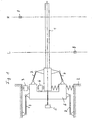
- the figures show a wheel balancing machine with a measuring arrangement, as it is known from EP 1 108 204 B1.
- a measuring shaft of the wheel balancing machine is supported with pretensioning via two measuring sensors 3, 4 and an intermediate frame 6 relative to the machine frame 2.
- a test weight 8 for example, with a calibration mass of 100 g in a certain radius in a left calibration plane L on the measuring shaft 1 are attached. Furthermore, the test weight 8 can be fixed to the measuring shaft 1 in a right-hand calibration plane R at the same radial distance as in the left-hand calibration plane.
- the calibration planes L and R may be different from the balancing planes of a wheel to be balanced or have the same position as the balancing planes.
- a calibration run is performed with bare measuring shaft 1 without test weight.
- a force F 03 is measured by the encoder 3 and a force F 04 by the encoder 4.
- the measurement of the forces in the encoders 3 and 4 takes place with reference to the angle using the rotary encoder 5.
- the measuring electronics 9 of the balancing machine forms from these measurement results an unbalance vector U 0 in a known manner.
- test weight 8 in the left calibration plane L is fixed to the measuring shaft 1 in the predetermined radius.
- 3 and 4 forces K L3 and K L4 are measured by the encoders, which result from the centrifugal forces generated by the test weight 8. These forces are measured angle-related using the rotary encoder 5 and from this an unbalance vector U L determined by the measuring electronics 9 for the imbalance display on the machine.
- test weight 8 is attached to the measuring shaft 1 at the same distance as in the left calibration plane L in the right calibration plane R.
- 3 and 4 forces K R3 and K R4 are measured by the encoders, from which with the aid of the rotary encoder 5, an unbalance vector U R determined using the machine electronics 9 and displayed on the display device.
- an additional evaluation of the force signals generated by at least one of the two encoders 3 and 4 is performed in the invention.
- the forces of the encoder 3 are evaluated.
- the encoder 3 supplies during the above-described successive calibration runs the force signals F 03 , F L3 and F R3 . Due to the different lever arms, which act on insertion of the test weight 8 into the left and the right calibration plane, F R3 > F L3 > F 03 .
- an additional evaluation device 11 which may also be integrated into the machine or measuring electronics 9, this is detected from the difference in forces resulting order. With the aid of the evaluation device 11, the largest force F R3 is assigned to the calibration run, in which the test weight 8 was arranged in the right-hand calibration plane R, and thus assigned to the unbalance vector U R determined for this purpose.
- the second largest force F L3 is assigned to the calibration run, in which the test weight 8 was arranged in the left calibration plane L, and thus assigned to the imbalance vector U L determined in this case.
- the smallest measured force F 03 is assigned to the calibration run, in which the bare measuring shaft 1 circulated, assigned to the imbalance vector U 0 determined in the process.
- the assignment of the determined imbalance vectors to the calibration planes is performed.
- the calibration can be carried out in a known manner such that for the left calibration level L corresponding electrical or electronic components of the measuring electronics 9 and / or the display device 10 with a on the Machine provided actuator, for example in the form of a knob, are adjusted until the display of the unbalance vector in the right calibration level R is zero.
- corresponding electronic or electrical components of the measuring electronics 9 or display device 10 can be adjusted so that the imbalance vector display for the left calibration level L is zero or disappears and only the vector display for the right Kibribrierebene R is present. Furthermore, an approximation of the mass display and angle display for the respective calibration level can be done.
- the described assignment of the determined unbalance vectors to the associated calibration runs and thus to the associated calibration planes can be carried out in such balancing machines in which different distances of the calibration planes of the at least one encoder of the measuring arrangement are present.
- the invention thus shows a method and a device for calibrating a wheel balancing machine which has a rotatably mounted measuring shaft 1 for unbalance measurement of a vehicle wheel, in which a test weight 8 is arranged chronologically successively in a left calibration plane L and a right calibration plane R and thereby calibration runs are performed , And further with bare measuring shaft 1, a calibration run is performed.
- These calibration runs can be performed on each other in any order.
- the forces measured by at least one of the two encoders 3, 4 in the three calibration runs are evaluated with respect to their differences, the lowest force being the calibration gage with the bare measuring shaft 1, the largest measured force of the calibration plane R farthest from the giver lies, and the intervening Force of the calibration plane L, which is closer to the encoder, are assigned for the calibration of the wheel balancing machine.
- an angular difference of in particular 180 ° for the attachment points of the test weight in the calibration planes is preferred;
- the attachment points in the two calibration planes can also have the same angular position.
Description
Die Erfindung betrifft ein Verfahren zur Kalibrierung einer Radauswuchtmaschine, welche eine drehbar gelagerte Messwelle zur Unwuchtmessung von Fahrzeugrädern aufweist, bei dem wenigstens ein Unwuchtmesslauf mit bloßer Messwelle und wenigstens zwei weitere aufeinanderfolgende Unwuchtmessläufe, bei denen Testgewichte mit vorgegebener Masse in zwei einen axialen Abstand voneinander aufweisenden vorgegebenen Kalibrierebenen befestigt werden, durchgeführt werden und in Abhängigkeit von den dabei von zwei an die Messwelle gekoppelten Messgebern gemessenen Kräften die Messelektronik und/oder die Messanzeige der Radauswuchtmaschine eingestellt wird bzw. werden sowie eine Radauswuchtmaschine.The invention relates to a method for calibrating a wheel balancing machine, which has a rotatably mounted measuring shaft for unbalance measurement of vehicle wheels, in which at least one unbalance measuring run with bare measuring shaft and at least two further consecutive unbalance measuring runs, in which test weights with predetermined mass in two an axial distance from each other having predetermined Calibration levels are attached, carried out and depending on the case of two sensors coupled to the measuring shaft measured forces the measuring electronics and / or the measurement display of Radauswuchtmaschine is or will be set and a Radauswuchtmaschine.
Ein derartiges Verfahren ist aus der EP 0 133 229 B1 bekannt. Damit die in den verschiedenen Messläufen gewonnenen Kräfte der jeweils zugehörigen Kalibrierebene zugeordnet werden, ist es bekannt, die wenigstens drei Unwuchtmessläufe für die Kalibrierung in einer bestimmten Reihenfolge durchzuführen. Beispielsweise wird zuerst der Messlauf mit bloßer Messwelle ohne Testgewichte, dann der Messlauf mit in der linken Kalibrierebene eingesetztem Testgewicht und anschließend der Messlauf mit in der rechten Kalibrierebene eingesetztem Testgewicht durchgeführt. Hierbei besteht jedoch die Gefahr, dass die Messläufe in ihrer Reihenfolge vertauscht werden, so dass eine falsche Kalibrierung der Radauswuchtmaschine sich ergibt. Außerdem treten Fehler der Kalibrierung dadurch auf, dass zwei Messläufe mit bloßer Messwelle und ein Messlauf mit einem Testgewicht in einer der beiden Kalibrierebenen durchgeführt wird.Such a method is known from EP 0 133 229 B1. So that the forces obtained in the various measuring runs are assigned to the respective associated calibration level, it is known to carry out the at least three unbalance measuring runs for the calibration in a specific sequence. For example, the measurement run with a bare measuring shaft without test weights, then the measurement run with the test weight inserted in the left calibration plane and then the measurement run with the test weight inserted in the right calibration plane are performed first. However, there is a risk that the measuring runs are reversed in their order, resulting in an incorrect calibration of the wheel balancing machine. In addition, errors of calibration occur in that two runs with bare measuring shaft and a test run is carried out with a test weight in one of the two calibration planes.
Aufgabe der Erfindung ist es daher, ein Verfahren der eingangs genannten Art zu schaffen, bei welchem unabhängig von der Reihenfolge der bei der Kalibrierung durchgeführten Unwuchtmessläufe eine korrekte Kalibrierung der Radauswuchtmaschine erreicht wird.The object of the invention is therefore to provide a method of the type mentioned, in which, regardless of the sequence of performed in the calibration unbalance measurement runs a correct calibration of Radauswuchtmaschine is achieved.
Diese Aufgabe wird erfindungsgemäß durch die kennzeichnenden Merkmale des Patentanspruches 1 gelöst.This object is achieved by the characterizing features of claim 1.
Hierzu werden die von einem der beiden Messgeber in den wenigstens drei Unwuchtmessläufen bei der Kalibrierung jeweils gemessenen Kräfte zueinander in Beziehung gebracht, wobei die geringste Kraft der drei gemessenen Kräfte dem Unwuchtmesslauf mit der bloßen Messwelle zugeordnet wird und die bei den wenigstens zwei weiteren Messläufen gemessenen Kräfte aufgrund ihrer Unterschiede der jeweils zugehörigen Kalibrierebene zugeordnet werden. Hierzu wird die größere Kraft der Kalibrierebene zugeordnet, welche weiter vom Messgeber entfernt liegt, und die geringere Kraft der Kalibrierebene zugeordnet, welche näher zum Messgeber liegt. Auf diese Weise erreicht man eine korrekte Zuordnung der bei den jeweiligen Unwuchtmessläufen (Kalibrierläufen) gemessenen Kräfte und der abgeleiteten Unwuchtvektoren zu dem Kalibrierlauf mit bloßer Welle sowie zu dem Kalibrierlauf mit in der linken Kalibrierebene eingesetztem Testgewicht und zu dem Kalibrierlauf mit in der rechten Kalibrierebene eingesetztem Testgewicht. Diese korrekte Zuordnung erreicht man unabhängig davon, in welcher Reihenfolge die Unwuchtmessläufe (Kalibrierläufe) durchgeführt werden.For this purpose, the forces measured by one of the two measuring sensors in the at least three unbalance measuring runs are correlated with each other, whereby the lowest force of the three measured forces is assigned to the unbalance measuring run with the bare measuring shaft and the forces measured in the at least two further measuring runs be assigned due to their differences of the respective associated calibration level. For this purpose, the greater force is assigned to the calibration plane, which lies farther away from the encoder, and the lower force is assigned to the calibration plane, which is closer to the encoder. In this way, one obtains a correct assignment of the forces measured in the respective imbalance measuring runs (calibration runs) and the derived unbalance vectors to the calibration run with bare wave and to the calibration run with test weight inserted in the left calibration plane and to the calibration run with test weight inserted in the right calibration plane , This correct assignment is achieved regardless of the sequence in which the unbalance measurement runs (calibration runs) are performed.
Die Erfindung eignet sich zur Kalibrierung von Radauswuchtmaschinen, bei denen die an die Messwelle gekoppelten Messgeber im axialen Abstand voneinander angeordnet sind, wie es beispielsweise aus der EP 0 133 229 B1 bekannt ist. Diese Kalibrierung kann jedoch auch bei solchen Radauswuchtmaschinen durchgeführt werden, wie sie aus EP 1 108 204 B1 oder aus EP 0 058 860 B1 bekannt sind.The invention is suitable for calibrating wheel balancers, in which the measuring sensors coupled to the measuring shaft are arranged at an axial distance from one another, as is known, for example, from EP 0 133 229 B1. However, this calibration can also be carried out in wheel balancers such as are known from EP 1 108 204 B1 or from EP 0 058 860 B1.
In vorteilhafter Weise wird das Testgewicht, welches eine Masse von beispielsweise 100 g aufweist, in den aufeinanderfolgenden Messläufen mit einem bestimmten Winkelunterschied in den Kalibrierebenen an der Messwelle in gleichen Radien befestigt. Die Befestigung kann dabei an einem dynamisch ausgewuchteten Rotor, welcher an der Messwelle befestigt ist, erfolgen. Vorzugsweise beträgt der Winkelunterschied 180°.Advantageously, the test weight, which has a mass of, for example, 100 g, is fixed in the successive measuring runs with a specific angular difference in the calibration planes on the measuring shaft in equal radii. The attachment can be done on a dynamically balanced rotor which is fixed to the measuring shaft. Preferably, the angle difference is 180 °.
Vorzugsweise wird von den bei den Unwuchtvektoren, welche bei den Kalibrierläufen mit den Testgewichten ermittelt werden, vektoriell der Unwuchtvektor subtrahiert, welcher beim Kalibrierlauf der bloßen Messwelle ohne Testgewicht ermittelt wurde.Preferably, in the case of the imbalance vectors which are determined during the calibration runs with the test weights, vectorially the imbalance vector which was determined during the calibration run of the bare measuring shaft without test weight is subtracted.
Bei insbesondere mit Winkelunterschied in den Kalibrierebenen angeordnetem Testgewicht wirkt sich eine eventuelle Restunwucht der bloßen Messwelle unterschiedlich auf die in den beiden Kalibrierläufen ermittelten Unwuchten aus. Durch oben beschriebene Vektorsubstraktion wird dieser unterschiedliche Einfluss kompensiert.In particular arranged with angular difference in the calibration planes test weight, any residual imbalance of the bare measuring shaft has a different effect on the unbalance determined in the two calibration runs. The vector substraction described above compensates for this different influence.
Anhand der Figuren wird die Erfindung noch näher erläutert.With reference to the figures, the invention will be explained in more detail.
Es zeigt
- Fig. 1
- eine Messanordnung einer Radauswuchtmaschine; und
- Fig. 2
- ein Blockschaltbild zur Auswertung der beim Kalibrieren gemessenen Kräfte in der Radauswuchtmaschine.
- Fig. 1
- a measuring arrangement of a wheel balancing machine; and
- Fig. 2
- a block diagram for evaluating the measured forces during calibration in Radauswuchtmaschine.
Die Figuren zeigen eine Radauswuchtmaschine mit einer Messanordnung, wie sie aus EP 1 108 204 B1 bekannt ist. Bei dieser Messanordnung wird eine Messwelle der Radauswuchtmaschine mit Vorspannung über zwei Messgeber 3, 4 und einen Zwischenrahmen 6 gegenüber dem Maschinenrahmen 2 abgestützt. Eine weitere Abstützung gegenüber dem Maschinenrahmen 2 erfolgt über Stützhebel 7 in der Weise, wie sie im einzelnen in EP 1 108 204 B1 beschrieben ist.The figures show a wheel balancing machine with a measuring arrangement, as it is known from EP 1 108 204 B1. In this measuring arrangement, a measuring shaft of the wheel balancing machine is supported with pretensioning via two
Mittels eines nicht näher dargestellten, insbesondere dynamisch ausgewuchteten Rotors kann ein Testgewicht 8 beispielsweise mit einer Kalibriermasse von 100 g in einem bestimmten Radius in einer linken Kalibrierebene L an der Messwelle 1 befestigt werden. Ferner kann das Testgewicht 8 in einer rechten Kalibrierebene R im gleichen radialen Abstand, wie in der linken Kalibrierebene, an der Messwelle 1 befestigt werden. Die Kalibrierebenen L und R können unterschiedlich zu den Ausgleichsebenen eines auszuwuchtenden Rades sein oder die gleiche Lage wie die Ausgleichsebenen aufweisen.By means of a rotor, not shown in detail, in particular dynamically balanced, a
Zur Kalibrierung der Radauswuchtmaschine, insbesondere einer Messelektronik 9 und einer Unwuchtanzeigeeinrichtung 10 wird ein Kalibrierlauf mit bloßer Messwelle 1 ohne Testgewicht durchgeführt. Dabei wird vom Messgeber 3 eine Kraft F03 und vom Messgeber 4 eine Kraft F04 gemessen. Die Messung der Kräfte in den Messgebern 3 und 4 erfolgt winkelbezogen mit Hilfe des Drehwinkelgebers 5. Die Messelektronik 9 der Auswuchtmaschine bildet aus diesen Messergebnissen einen Unwuchtvektor U0 in bekannter Weise.For calibrating the wheel balancing machine, in particular measuring electronics 9 and an
In einem weiteren Kalibrierlauf wird das Testgewicht 8 in der linken Kalibrierebene L im vorbestimmten Radius an der Messwelle 1 befestigt. Dabei werden von den Messgebern 3 und 4 Kräfte KL3 und KL4 gemessen, welche aus den vom Testgewicht 8 erzeugten Fliehkräften resultieren. Auch diese Kräfte werden mit Hilfe des Drehwinkelgebers 5 winkelbezogen gemessen und hieraus ein Unwuchtvektor UL von der Messelektronik 9 für die Unwuchtanzeige an der Maschine ermittelt.In a further calibration run, the
In einem weiteren Kalibrierlauf wird das Testgewicht 8 in gleichem Abstand wie in der linken Kalibrierebene L in der rechten Kalibrierebene R an der Messwelle 1 befestigt. Bei diesem Kalibrierlauf werden von den Messgebern 3 und 4 Kräfte KR3 und KR4 gemessen, aus denen mit Hilfe des Drehwinkelgebers 5 ein Unwuchtvektor UR mit Hilfe der Maschinenelektronik 9 ermittelt und an der Anzeigeeinrichtung angezeigt wird.In a further calibration run, the
Die Maschinenelektronik herkömmlicher Radauswuchtmaschinen ist nicht in der Lage zu unterscheiden, ob bei der Messung das Testgewicht 8 in der linken Kalibrierebene L oder in der rechten Kalibrierebene R angeordnet ist. Bei herkömmlichen Maschinen wird daher eine bestimmte Reihenfolge, beispielsweise derart, wie sie oben beschrieben ist, eingehalten, um eine Zuordnung der ermittelten Unwuchten zu den Kalibrierläufen zu erhalten. In der Praxis ergibt sich hieraus jedoch die Gefahr einer falschen Kalibrierung der Maschine, da eine Verwechslung der Reihenfolge der Kalibrierläufe nicht auszuschließen ist und in der Praxis häufig vorkommt.The machine electronics of conventional wheel balancers are not able to distinguish whether the
Um diese Fehlerquelle auszuschließen, wird bei der Erfindung eine zusätzliche Auswertung der von wenigstens einem der beiden Messgeber 3 und 4 erzeugten Kräftesignale durchgeführt. Im dargestellten Ausführungsbeispiel werden die Kräfte des Messgebers 3 ausgewertet. Der Messgeber 3 liefert während der oben erläuterten aufeinanderfolgenden Kalibrierläufe die Kräftesignale F03, FL3 und FR3. Aufgrund der unterschiedlichen Hebelarme, welche beim Einsetzen des Testgewichts 8 in die linke und die rechte Kalibrierebene wirken, ist FR3 > FL3 > F03. In einer zusätzlichen Auswerteeinrichtung 11, welche auch in die Maschinen- oder Messelektronik 9 integriert sein kann, wird diese sich aus den Kräfteunterschieden ergebenden Reihenfolge erfasst. Mit Hilfe der Auswerteeinrichtung 11 wird die größte Kraft FR3 dem Kalibrierlauf zugeordnet, bei welchen das Testgewicht 8 in der rechten Kalibrierebene R angeordnet war, und damit dem hierzu bestimmten Unwuchtvektor UR zugeordnet.To exclude this source of error, an additional evaluation of the force signals generated by at least one of the two
Die zweitgrößte Kraft FL3 wird dem Kalibrierlauf zugeordnet, bei welchem das Testgewicht 8 in der linken Kalibrierebene L angeordnet war, und somit dem dabei ermittelten Unwuchtvektor UL zugeordnet.The second largest force F L3 is assigned to the calibration run, in which the
Die kleinste gemessene Kraft F03 wird dem Kalibrierlauf zugeordnet, bei welchem die bloße Messwelle 1 umlief, dem dabei ermittelten Unwuchtvektor U0 zugeordnet. Im Gegensatz zum Stand der Technik wird bei der Erfindung in Abhängigkeit von den Kräften, welche in den jeweiligen Kalibrierläufen von wenigstens einem der Messgeber gemessen werden, die Zuordnung der ermittelten Unwuchtvektoren zu den Kalibrierebenen, wie erläutert, durchgeführt.The smallest measured force F 03 is assigned to the calibration run, in which the bare measuring shaft 1 circulated, assigned to the imbalance vector U 0 determined in the process. In contrast to the prior art, in the invention, depending on the forces which are measured in the respective calibration runs of at least one of the encoders, the assignment of the determined imbalance vectors to the calibration planes, as explained, is performed.
Anstelle der Kraftmesswerte des Messgebers 3 können in gleicher Weise die vom Messgeber 4 gemessenen Kräfte F04, FL4 und FR4, wie beschrieben, ausgewertet werden. Für eine eventuelle Kontrolle können die Auswertungen beider Messgeber 3 und 4 miteinander verglichen werden.Instead of the force measurements of the
Auf diese Weise erreicht man eine Zuordnung der bei den Kalibrierläufen ermittelten Unwuchtvektoren zu den zugehörigen Kalibrierläufen und zugehörigen Kalibrierebenen L und R unabhängig von der Reihenfolge der durchgeführten Kalibrierläufe. Mit Hilfe der Anzeigeeinrichtung 10, an welcher die Unwuchtvektoren nach Masse und Winkellage angezeigt werden, kann die Kalibrierung in bekannter Weise derart erfolgen, dass für die linke Kalibrierebene L entsprechende elektrische oder elektronische Bauteile der Messelektronik 9 und/oder der Anzeigeeinrichtung 10 mit einem an der Maschine vorgesehenen Betätigungselementes, beispielsweise in Form eines Drehknopfes, so lange verstellt werden, bis die Anzeige des Unwuchtvektors in der rechten Kalibrierebene R zu Null wird. In gleicher Weise können mit Hilfe eines weiteren Betätigungselementes entsprechende elektronische oder elektrische Bauteile der Messelektronik 9 oder Anzeigeeinrichtung 10 so verstellt werden, dass die Unwuchtvektoranzeige für die linke Kalibrierebene L zu Null wird oder verschwindet und nur noch die Vektoranzeige für die rechte Kälibrierebene R vorliegt. Ferner kann eine Angleichung der Massenanzeige und Winkelanzeige für die jeweilige Kalibrierebene erfolgen.In this way, an allocation of the unbalance vectors determined during the calibration runs to the associated calibration runs and associated calibration planes L and R is achieved independently of the sequence of the calibration runs performed. With the aid of the
Die beschriebene Zuordnung der ermittelten Unwuchtvektoren zu den dazugehörigen Kalibrierläufen und damit zu den zugehörigen Kalibierebenen kann bei solchen Auswuchtmaschinen durchgeführt werden, bei denen unterschiedliche Abstände der Kalibrierebenen von dem wenigstens einen Messgeber der Messanordnung vorhanden sind.The described assignment of the determined unbalance vectors to the associated calibration runs and thus to the associated calibration planes can be carried out in such balancing machines in which different distances of the calibration planes of the at least one encoder of the measuring arrangement are present.
Mit Hilfe des erläuterten Verfahrens können auch solche Fehler erfasst werden, bei denen einer der wenigstens drei Kalibrierläufe doppelt durchgeführt wurde. Es ergeben sich dann für die beiden Kalibrierläufe, insbesondere bei den Kraftmesswerten und auch bei den Winkelmesswerten keine oder nur geringe Unterschiede. Wenn beispielsweise zwei Kalibrierläufe mit dem Testgewicht 8 in der linken Kalibrierebene und ein Kalibrierlauf mit bloßer Messwelle 1 durchgeführt wurden, ergeben sich für die Kalibrierläufe mit dem Testgewicht keine oder nur geringe Unterschiede bei den Kraftmesswerten und Winkelmesswerten. Äquivalente Ergebnisse ergeben sich bei Kalibrierläufen, bei denen nur in der rechten Kalibrierebene das Testgewicht eingesetzt war oder bei zwei Kalibrierläufen mit bloßer Messwelle 1 und dem Testgewicht in einem der beiden Kalibrierebenen. Mit Hilfe der Erfindung können derart fehlerhaft durchgeführte Kalibrierungen erfasst und gegebenenfalls durch eine Fehleranzeige kenntlich gemacht werden.With the aid of the described method, it is also possible to detect those errors in which one of the at least three calibration runs has been performed twice. This results in no or only slight differences for the two calibration runs, in particular for the force measurements and also for the angle measurements. If, for example, two calibration runs were carried out with the
Die Erfindung zeigt somit ein Verfahren und eine Vorrichtung zur Kalibrierung einer Radauswuchtmaschine, welche eine drehbar gelagerte Messwelle 1 zur Unwuchtmessung eines Fahrzeugrades aufweist, bei dem ein Testgewicht 8 zeitlich aufeinanderfolgend in einer linken Kalibrierebene L und einer rechten Kalibrierebene R angeordnet wird und dabei Kalibrierläufe durchgeführt werden, und ferner mit bloßer Messwelle 1 ein Kalibrierlauf durchgeführt wird. Diese Kalibrierläufe können mit beliebiger Reihenfolge aufeinander erfolgen. Die von wenigstens einem der beiden Messgeber 3, 4 in den drei Kalibrierläufen gemessenen Kräfte werden im Hinblick auf ihre Unterschiede beurteilt, wobei die geringste Kraft dem Kalibriermesslauf mit der bloßen Messwelle 1, die größte gemessene Kraft der Kalibrierebene R, welche am weitesten vom Messgeber entfernt liegt, und die dazwischenliegende Kraft der Kalibrierebene L, welche näher zum Messgeber liegt, für die Kalibriereinstellung der Radauswuchtmaschine zugeordnet werden.The invention thus shows a method and a device for calibrating a wheel balancing machine which has a rotatably mounted measuring shaft 1 for unbalance measurement of a vehicle wheel, in which a
Ein Winkelunterschied von insbesondere 180° für die Befestigungsstellen des Testgewichtes in den Kalibrierebenen wird bevorzugt; jedoch können die Befestigungsstellen in den beiden Kalibrierebenen auch die gleich Winkellage aufweisen.An angular difference of in particular 180 ° for the attachment points of the test weight in the calibration planes is preferred; However, the attachment points in the two calibration planes can also have the same angular position.
- 11
- Messwellemeasuring shaft
- 22
- Maschinenrahmenmachine frame
- 3,43.4
- KraftmessgeberLoad cells
- 55
- DrehwinkelgeberRotary encoder
- 66
- Zwischenrahmenintermediate frame
- 77
- Stützhebelsupport lever
- 88th
- Testgewichttest weight
- 99
- Messelektronikmeasuring electronics
- 1010
- Anzeigeeinrichtungdisplay
- 1111
- zusätzliche Auswerteeinrichtungadditional evaluation device
Claims (5)
- A method of calibrating a wheel balancing machine having a rotatably mounted measuring shaft for unbalance measurement on vehicle wheels, in which at least one unbalance measuring run with a bare measuring shaft and at least two further successive unbalance measuring runs in which a test weight of a predetermined mass is respectively fixed in two predetermined calibration planes arranged at an axial spacing from each other are effected and in dependence on the forces measured in that procedure with two force measuring senders coupled to the measuring shaft in force-locking relationship the electronic measuring system and/or the display device of the wheel balancing machine is or are set,
characterised in that the forces respectively measured by at least one of the two measuring senders in the three unbalance measuring runs are brought into relationship with each other in respect of their differences, wherein the smallest force is associated with the unbalance measuring run with the bare shaft and the forces measured in the at least two further measuring runs are associated with the respectively belonging calibration plane on the basis of their differences, wherein the higher force is associated with the calibration plane which is further away from the at least one measuring sender and the lower force is associated with the calibration plane which is closer to the at least one measuring sender, for calibration setting. - A method according to claim 1
characterised in that the test weight is fixed to the measuring shaft with a predetermined angular difference in the calibration runs. - A method according to claim 2
characterised in that the angular difference is 180°. - A method according to one of claims 1 to 3
characterised in that the unbalance vector which is ascertained in the measuring run with a bare measuring shaft is vectorially subtracted from the unbalance vectors ascertained in the unbalance measuring runs with the test weight. - A wheel balancing machine comprising a measuring shaft (1) which is to be driven in rotation, at least two force measuring senders (3, 4) which are connected to the measuring shaft (1) is force-locking relationship, a rotary angle sender (5) which is connected to the measuring shaft (1) and which supplies angle signals proportional to the respective rotary angles of the measuring shaft (1), an electronic measuring system (9) to which the force measuring senders (3, 4) and the rotary angle sender (5) are connected and a display device (10) for the display of ascertained unbalanced vectors for a vehicle wheel to be fixed to the measuring shaft (1),
characterised in that connected to at least one of the force measuring senders (3, 4) is an evaluation device (11) which, in a calibration operation, detects the forces measured in at least three calibration runs with a bare measuring shaft (1) and two further calibration runs with a test weight (8) fitted in a left-hand calibration plane (L) and in a right-hand calibration plane (R) as well as the differences in the measured forces and in dependence on the differences in the measured forces associates the unbalance vectors (UL, UR) ascertained in the calibration runs with the two calibration planes (L, R).
Priority Applications (2)
| Application Number | Priority Date | Filing Date | Title |
|---|---|---|---|
| EP20030021761 EP1519177B1 (en) | 2003-09-25 | 2003-09-25 | Method for calibration of a tire balancing machine and apparatus therefore |
| DE50303119T DE50303119D1 (en) | 2003-09-25 | 2003-09-25 | Method for calibrating a wheel balancer and wheel balancer |
Applications Claiming Priority (1)
| Application Number | Priority Date | Filing Date | Title |
|---|---|---|---|
| EP20030021761 EP1519177B1 (en) | 2003-09-25 | 2003-09-25 | Method for calibration of a tire balancing machine and apparatus therefore |
Publications (2)
| Publication Number | Publication Date |
|---|---|
| EP1519177A1 EP1519177A1 (en) | 2005-03-30 |
| EP1519177B1 true EP1519177B1 (en) | 2006-04-26 |
Family
ID=34178502
Family Applications (1)
| Application Number | Title | Priority Date | Filing Date |
|---|---|---|---|
| EP20030021761 Expired - Lifetime EP1519177B1 (en) | 2003-09-25 | 2003-09-25 | Method for calibration of a tire balancing machine and apparatus therefore |
Country Status (2)
| Country | Link |
|---|---|
| EP (1) | EP1519177B1 (en) |
| DE (1) | DE50303119D1 (en) |
Families Citing this family (2)
| Publication number | Priority date | Publication date | Assignee | Title |
|---|---|---|---|---|
| CN109238565A (en) * | 2018-08-29 | 2019-01-18 | 深圳市元征科技股份有限公司 | A kind of tire balancing equipment calibration reminding method, system and relevant device |
| CN113532733B (en) * | 2021-08-27 | 2023-08-08 | 四川大学 | Thin film type pressure sensor calibration device and calibration method |
Family Cites Families (2)
| Publication number | Priority date | Publication date | Assignee | Title |
|---|---|---|---|---|
| US4494400A (en) * | 1983-07-28 | 1985-01-22 | Fmc Corporation | Wheel balancer two plane calibration apparatus and method |
| US5396436A (en) * | 1992-02-03 | 1995-03-07 | Hunter Engineering Corporation | Wheel balancing apparatus and method with improved calibration and improved imbalance determination |
-
2003
- 2003-09-25 DE DE50303119T patent/DE50303119D1/en not_active Expired - Lifetime
- 2003-09-25 EP EP20030021761 patent/EP1519177B1/en not_active Expired - Lifetime
Also Published As
| Publication number | Publication date |
|---|---|
| DE50303119D1 (en) | 2006-06-01 |
| EP1519177A1 (en) | 2005-03-30 |
Similar Documents
| Publication | Publication Date | Title |
|---|---|---|
| EP0247350B1 (en) | Method and device for optimizing the balance of a vehicle wheel | |
| DE102008006865B4 (en) | Inductive torque sensor | |
| DE4143624C2 (en) | Balancing machine for motor vehicle wheels | |
| DE102016005889B4 (en) | A shaft accuracy measuring device for measuring the accuracy of an output shaft of an engine | |
| EP0273063B1 (en) | Method for calibrating a balance apparatus | |
| WO2000014503A1 (en) | Device for measuring the forces generated by a rotor imbalance | |
| EP0756165A2 (en) | Method and device for calibrating of torque in measuring installation | |
| EP0590169B1 (en) | Procedure for imbalance determination of a rotary driven inflexible shaft | |
| EP0942273B1 (en) | Method for determining the compensation of the unbalance by elastic rotors | |
| DE2827669C2 (en) | Method for determining the magnitude and phase position of vibrations detected by transducers, especially in balancing technology | |
| EP1519177B1 (en) | Method for calibration of a tire balancing machine and apparatus therefore | |
| DE3040713C2 (en) | Device for setting a force-measuring balancing machine | |
| DE2847295C2 (en) | Device for determining the unbalance of a rotating body held by a receptacle of a balancing machine with a bearing stand | |
| DE3026232C2 (en) | Method and device for displaying the size of an imbalance when balancing rotors | |
| DE10206259B4 (en) | Method for correcting lateral force measurements | |
| DE102017002891A1 (en) | Method for determining a chassis geometry | |
| DE3002682A1 (en) | METHOD AND DEVICE FOR MEASURING DIFFERENTIAL DIFFERENCES ON A ROTOR, ESPECIALLY A GYRO | |
| EP1231457B1 (en) | Procedure and device for calibrating an arrangement for measuring unbalance | |
| EP0259513B1 (en) | Method for the precision measurement of caster and camber in motor vehicles | |
| EP0797086B1 (en) | System for balancing a vehicle wheel | |
| DE10056956B4 (en) | Method and device for assessing an eccentric position of an acceleration sensor | |
| DE19813881A1 (en) | Method for determining an unbalance and device | |
| DE10002138B4 (en) | An eccentricity error correction device and a method for eccentricity error correction in an acceleration sensor in an acceleration generation device | |
| EP1739390A1 (en) | Method and device for caster measurement | |
| EP0475060B1 (en) | Method and device for automatic recognition of constraining forces by balancing rotors in balancing machines with force measurement |
Legal Events
| Date | Code | Title | Description |
|---|---|---|---|
| PUAI | Public reference made under article 153(3) epc to a published international application that has entered the european phase |
Free format text: ORIGINAL CODE: 0009012 |
|
| 17P | Request for examination filed |
Effective date: 20040924 |
|
| AK | Designated contracting states |
Kind code of ref document: A1 Designated state(s): AT BE BG CH CY CZ DE DK EE ES FI FR GB GR HU IE IT LI LU MC NL PT RO SE SI SK TR |
|
| AX | Request for extension of the european patent |
Extension state: AL LT LV MK |
|
| GRAP | Despatch of communication of intention to grant a patent |
Free format text: ORIGINAL CODE: EPIDOSNIGR1 |
|
| GRAS | Grant fee paid |
Free format text: ORIGINAL CODE: EPIDOSNIGR3 |
|
| AKX | Designation fees paid |
Designated state(s): DE ES FR GB IT |
|
| GRAA | (expected) grant |
Free format text: ORIGINAL CODE: 0009210 |
|
| AK | Designated contracting states |
Kind code of ref document: B1 Designated state(s): DE ES FR GB IT |
|
| PG25 | Lapsed in a contracting state [announced via postgrant information from national office to epo] |
Ref country code: GB Free format text: LAPSE BECAUSE OF FAILURE TO SUBMIT A TRANSLATION OF THE DESCRIPTION OR TO PAY THE FEE WITHIN THE PRESCRIBED TIME-LIMIT Effective date: 20060426 |
|
| REG | Reference to a national code |
Ref country code: GB Ref legal event code: FG4D Free format text: NOT ENGLISH |
|
| REF | Corresponds to: |
Ref document number: 50303119 Country of ref document: DE Date of ref document: 20060601 Kind code of ref document: P |
|
| PG25 | Lapsed in a contracting state [announced via postgrant information from national office to epo] |
Ref country code: ES Free format text: LAPSE BECAUSE OF FAILURE TO SUBMIT A TRANSLATION OF THE DESCRIPTION OR TO PAY THE FEE WITHIN THE PRESCRIBED TIME-LIMIT Effective date: 20060806 |
|
| GBV | Gb: ep patent (uk) treated as always having been void in accordance with gb section 77(7)/1977 [no translation filed] |
Effective date: 20060426 |
|
| ET | Fr: translation filed | ||
| PLBE | No opposition filed within time limit |
Free format text: ORIGINAL CODE: 0009261 |
|
| STAA | Information on the status of an ep patent application or granted ep patent |
Free format text: STATUS: NO OPPOSITION FILED WITHIN TIME LIMIT |
|
| 26N | No opposition filed |
Effective date: 20070129 |
|
| REG | Reference to a national code |
Ref country code: FR Ref legal event code: PLFP Year of fee payment: 14 |
|
| REG | Reference to a national code |
Ref country code: FR Ref legal event code: PLFP Year of fee payment: 15 |
|
| PGFP | Annual fee paid to national office [announced via postgrant information from national office to epo] |
Ref country code: FR Payment date: 20170925 Year of fee payment: 15 |
|
| PGFP | Annual fee paid to national office [announced via postgrant information from national office to epo] |
Ref country code: DE Payment date: 20171005 Year of fee payment: 15 |
|
| REG | Reference to a national code |
Ref country code: DE Ref legal event code: R119 Ref document number: 50303119 Country of ref document: DE |
|
| PG25 | Lapsed in a contracting state [announced via postgrant information from national office to epo] |
Ref country code: DE Free format text: LAPSE BECAUSE OF NON-PAYMENT OF DUE FEES Effective date: 20190402 |
|
| PG25 | Lapsed in a contracting state [announced via postgrant information from national office to epo] |
Ref country code: FR Free format text: LAPSE BECAUSE OF NON-PAYMENT OF DUE FEES Effective date: 20180930 |
|
| PGFP | Annual fee paid to national office [announced via postgrant information from national office to epo] |
Ref country code: IT Payment date: 20220926 Year of fee payment: 20 |
|
| P01 | Opt-out of the competence of the unified patent court (upc) registered |
Effective date: 20230517 |